Table of Contents
Advertisement
Doc. n.: M0145Db.docx
Load cells digital interface with indicator
USE AND MAINTENANCE MANUAL
Manufacturer
Series
Typology
LOGIC S.r.l
.
codice fiscale / partita I.V.A. IT00842600181
Tribunale di PAVIA n. ORD. 31473 n. SOC. 4719 n. FASC. 6024 - CCIAA 154531
LOGIC S.r.l.
Via Del Tovo 5/3
I-27020 Travacò Sicc. PV
Italy
NET
DLC
This manual consists of 78 pages, annexes excluded.
T.+39.0382.482657
F.+39.0382.1850248
SERIES
I-27020 Travacò Siccomario (PV)
Load cells digital interface with indicator
Mod. L0006A01 del 30/05/2016
www.logic-pavia.it
info@logic-pavia.it
INSTRUMENT DATA
LOGIC S.r.l.
Via del Tovo 5/3
Italy
NET
DLC
Pagina 1 di 78
Advertisement
Table of Contents

Summary of Contents for Logic DLC NET Series
- Page 1 LOGIC S.r.l. T.+39.0382.482657 www.logic-pavia.it Via Del Tovo 5/3 F.+39.0382.1850248 info@logic-pavia.it I-27020 Travacò Sicc. PV Italy Doc. n.: M0145Db.docx SERIES Load cells digital interface with indicator USE AND MAINTENANCE MANUAL This manual consists of 78 pages, annexes excluded. INSTRUMENT DATA Manufacturer LOGIC S.r.l.
- Page 2 USE AND MAINTENANCE MANUAL – DLC Series INDEX INTENTIONALLY BLANK PAGE LOGIC S.r.l. - M0145Db.docx Page 2 of 78 Mod. L0006A01 of 30/05/2016...
- Page 3 Connection of start / stop button added. Configuration password added. Wall mounting drawings added. Declaration of 03/10/2016 conformity directives updated. 01/03/2017 Updated device name of DLC-NET-DIN (former DTR-NET-WM) LOGIC S.r.l. - M0145Db.docx Page 3 of 78 Mod. L0006A01 of 30/05/2016...
- Page 4 USE AND MAINTENANCE MANUAL – DLC Series INDEX BLANK PAGE LOGIC S.r.l. - M0145Db.docx Page 4 of 78 Mod. L0006A01 of 30/05/2016...
- Page 5 Load cells connection in ATEX Zone 1 (Zener barrier) ................22 3.5.3 Load cells connection in ATEX Zone 1 (active barrier) ................22 3.5.4 Connection to the junction box ....................... 23 LOGIC S.r.l. - M0145Db.docx Page 5 of 78 Mod. L0006A01 of 30/05/2016...
- Page 6 USE AND MAINTENANCE MANUAL – DLC Series INDEX Connecting of remote display via RS-485 ....................25 3.6.1 Introduction ............................25 3.6.2 RS-485 connection with Logic display DLC3-RD .................. 25 ® 3.6.3 RS-485 connection with display BEKA BA488C .................. 26 Fieldbus connection ........................... 28 ®...
- Page 7 Dosing of manual components ( ) ..................... 70 6.4.4 End of recipe ( )......................... 71 6.4.5 Recipe printing ( ) ..........................71 6.4.6 Abort of recipe ( ) ........................... 72 LOGIC S.r.l. - M0145Db.docx Page 7 of 78 Mod. L0006A01 of 30/05/2016...
- Page 8 USE AND MAINTENANCE MANUAL – DLC Series INDEX Decommissioning and dismantling ......................... 73 General indications ............................ 73 Procedure..............................73 FIGURES ................................75 TABLES ................................77 LOGIC S.r.l. - M0145Db.docx Page 8 of 78 Mod. L0006A01 of 30/05/2016...
- Page 9 European Community and the technical standards that include their requirements, as certified by the Declaration of Conformity issued by the manufacturer and attached to the manual. LOGIC S.r.l. - M0145Db.docx Page 9 of 78 Mod. L0006A01 of 30/05/2016...
- Page 10 In no event LOGIC S.r.l. shall bear the cost of charges for failure of production. LOGIC S.r.l. is liable for defects resulting from normal use of the machine and not those resulting from: ↘...
-
Page 11: Figure 1. Equipment Back Serigraphy
The instrument shows the following screen-printed marking on the case: Figure 1. Equipment back serigraphy On the chassis the serial number is indicated. Please communicate it to LOGIC S.r.l. in case of malfunctioning or replacement of the instrument. LOGIC S.r.l. - M0145Db.docx Page 11 of 78 Mod. - Page 12 Ai sensi dell’all. II-A della Direttiva 2006/42/CE I-27020 Travacò Siccomario (PV) (originale in lingua italiana) Italy Il Costruttore LOGIC S.r.l.. dichiara sotto la propria responsabilità che la macchina: The Manufacturer LOGIC S.r.l. declares under its responsibility that the machine: Costruttore LOGIC S.r.l.
-
Page 13: Figure 2. Diagram Of Operation And Power Supplies
(PLC or PC) with the use of the same power supply (+24 Vdc) common to other devices without any kind of problem. Figure 2. Diagram of operation and power supplies LOGIC S.r.l. - M0145Db.docx Page 13 of 78 Mod. L0006A01 of 30/05/2016... - Page 14 ↘ In the presence of earth resistance values low, connect to ground both sides of the screen to improve the effectiveness of the shielding. LOGIC S.r.l. - M0145Db.docx Page 14 of 78 Mod. L0006A01 of 30/05/2016...
-
Page 15: Figure 3. Mechanical Drawing Of Dlc Net
The instrument includes a case with IP20 protection. It will be the customer care to adequately protect the instrument in the installation environment. In Figure 4 DLC -WM mounting is depicted. DLC -WM can be installed on DIN rail. LOGIC S.r.l. - M0145Db.docx Page 15 of 78 Mod. L0006A01 of 30/05/2016... -
Page 16: Figure 4. Dlc Net -Wm Mechanical Drawing
-DIN has a 20 poles connector for an external keyboard (DLC-NET-KB) and can be installed vertically on a DIN rail as well (Figure 5). Figure 5. DLC -DIN mechanical drawing LOGIC S.r.l. - M0145Db.docx Page 16 of 78 Mod. L0006A01 of 30/05/2016... - Page 17 The connection to the load cells must be done with high quality shielded cable. The cable CAB-TS6 Logic model is recommended for all industrial applications including areas with risk of explosion. In applications with more load cells (platforms, tanks, silos, etc.), It is recommended the use of junction boxes that minimize differences in impedance or compensation on the signal branches.
-
Page 18: Figure 6. Layout Of The Terminal Blocks, Profibus-Dp
Figure 7. Layout of the terminal blocks, Profinet The terminal blocks have the following nomenclature: ↘ TB1: load cells connection ↘ TB2: Fieldbus ↘ TB3: serial connection for remote display ↘ TB4: power supply connection LOGIC S.r.l. - M0145Db.docx Page 18 of 78 Mod. L0006A01 of 30/05/2016... -
Page 19: Figure 8. Dlc Net -Wm Terminals (Model With On-Board Keyboard)
Figure 8. DLC -WM terminals (model with on-board keyboard) Figure 9. DTR -WM terminals (model with external keyboard) Where TB7 is a 20 poles connector reserved for keyboard connection. LOGIC S.r.l. - M0145Db.docx Page 19 of 78 Mod. L0006A01 of 30/05/2016... -
Page 20: Figure 10. Power Supply Connection
If the instrument outputs are connected to the dosage of components by solenoid valves and pumps, it is always necessary to unpower the instrument in case long times without supervision from operators, in order to prevent possible uncontrolled spills. LOGIC S.r.l. - M0145Db.docx Page 20 of 78 Mod. L0006A01 of 30/05/2016... -
Page 21: Figure 11. Load Cells Connection 6 Wires
Figure 11. Load cells connection 6 wires For connections with length less than 8 meters it is possible use the four-wire connection shown below. Figure 12. Load cells connection 4 wires LOGIC S.r.l. - M0145Db.docx Page 21 of 78 Mod. L0006A01 of 30/05/2016... -
Page 22: Figure 13. Load Cells Connection 6 Wires With Zener Barrier Z-Set3-Pf
(active barrier) In case of use of an active barrier, below is an example of connection with the active barrier mod. D1063S and cable CAB-TS6 supply by Logic. The color code of the CAB-TS6 cable remains to Table 4. LOGIC S.r.l. - M0145Db.docx Page 22 of 78 Mod. -
Page 23: Figure 14. Load Cells Connection 6 Wires With Active Barrier D1063S
TB3 – TB4 + Exc + excitation - Exc - excitation Black + Sig + signal Green - Sig - signal White GND / Shld cable shield GND / Shld LOGIC S.r.l. - M0145Db.docx Page 23 of 78 Mod. L0006A01 of 30/05/2016... -
Page 24: Figure 15. Connection To The Junction Box Jbox-V3(Ex1)
Figure 15. Connection to the junction box JBOX-V3(EX1) Load Cell #4 Load Cell #3 - sig +sig CAB-TS6 Extension Cable - Exc +Exc Shld Load Cell #2 Load Cell #1 LOGIC S.r.l. - M0145Db.docx Page 24 of 78 Mod. L0006A01 of 30/05/2016... -
Page 25: Figure 16. Connection Of Dlc
RS-485 connection with Logic display DLC3-RD The connection to the remote display Logic DLC3-RD is through an RS-485 serial cable with two wires, with the grounding of the shield. Always use shielded cables properly grounded, with a maximum cross section of 0,5 mm Table 6. -
Page 26: Figure 17. Connection Of Dlc
Installation Below are listed the serial configuration parameters for communication with . These parameters are already set on both instruments, with no need for any settings: Table 7. Serial port parameters for communication with Logic DLC3-RD Parameter Value Transmission Asynchronous... - Page 27 Parameter Value Transmission Asynchronous Baud rate 19200 Word 8 bits Stop bit Parity None Set up the KeyPad parameter to "Internal" to use the integrated buttons of BEKA. LOGIC S.r.l. - M0145Db.docx Page 27 of 78 Mod. L0006A01 of 30/05/2016...
-
Page 28: Figure 18. Instrument Connection To Profibus-Dp
Tx/Rx + Green TB2-8 Tx/Rx - ® Figure 18. Instrument connection to Profibus-DP Fieldbus ® Note how the termination on the connector is active on the last Profibus-DP node. LOGIC S.r.l. - M0145Db.docx Page 28 of 78 Mod. L0006A01 of 30/05/2016... -
Page 29: Figure 19. Instrument Connection To Profinet
Pin connector RJ45 bus Description Wire TB2-1 White-Orange TB2-2 Tx - Orange TB2-3 Rx + White-Green TB2-6 Rx - Green ® Figure 19. Instrument connection to Profinet Fieldbus LOGIC S.r.l. - M0145Db.docx Page 29 of 78 Mod. L0006A01 of 30/05/2016... -
Page 30: Figure 20. Connection To External Buttons Through Potential-Free Contacts
Table 13. Table connections from active source Pin on DLC Description TB3-4 0 Vdc (in common with external power supply) TB3-6 ÷ TB3-9 Inputs buttons (+24 Vdc external) LOGIC S.r.l. - M0145Db.docx Page 30 of 78 Mod. L0006A01 of 30/05/2016... -
Page 31: Figure 21. External Buttons Connection From Active Source
Out 2 (+24 Vdc transistor open-collector PNP), setpoint 2 TB6-3 Out 3 (+24 Vdc transistor open-collector PNP), setpoint 3 TB6-11 Out 4 (+24 Vdc transistor open-collector PNP), setpoint 4 Figure 22. Connection to setpoint output LOGIC S.r.l. - M0145Db.docx Page 31 of 78 Mod. L0006A01 of 30/05/2016... -
Page 32: Figure 23. Input And Output Connections For Dosing
0-20 mA or 4-20 mA The analog output 0-20 mA or 4-20 mA connections are highlighted in the table and figure below. It is necessary the expansion board -EB. LOGIC S.r.l. - M0145Db.docx Page 32 of 78 Mod. L0006A01 of 30/05/2016... -
Page 33: Figure 24. Analog Output Connection 0-20 Ma Or 4-20 Ma
USE AND MAINTENANCE MANUAL – DLC Series Installation Table 16. Analog output connection Pin on DLC Description TB5-4 Schield (SHLD) TB5-5 TB5-6 Figure 24. Analog output connection 0-20 mA or 4-20 mA LOGIC S.r.l. - M0145Db.docx Page 33 of 78 Mod. L0006A01 of 30/05/2016... -
Page 34: Figure 25. Printer Connection Through Rs232
DLC Table 18. Serial port parameters to be set on the printer Parameter Value Transmission Asynchronous Baud rate 9600 Word 7 bits Stop bit Parity Even LOGIC S.r.l. - M0145Db.docx Page 34 of 78 Mod. L0006A01 of 30/05/2016... -
Page 35: Figure 26. Signal Chart For The Data Weight Reading Through Parallel Output
In Figure 27 are shown the minimum deadlines to be respected for the connections. Figure 26. Signal chart for the data weight reading through parallel output LOGIC S.r.l. - M0145Db.docx Page 35 of 78 Mod. L0006A01 of 30/05/2016... -
Page 36: Figure 27. Connection For Parallel Interface Type Pnp
3.10.3 Connection for parallel interface type The connection of the outputs in NPN mode is described in the following table and figure. Expansion board –EB is needed for this purpose. LOGIC S.r.l. - M0145Db.docx Page 36 of 78 Mod. L0006A01 of 30/05/2016... -
Page 37: Figure 28. Connection For Parallel Interface Type Npn
Out 6 (+24 Vdc) TB6-5 Out 7 (+24 Vdc) TB6-13 Out 8 (+24 Vdc) TB6-8 0 Vdc TB6-15 Byte Select input (+24Vdc) Figure 28. Connection for parallel interface type NPN LOGIC S.r.l. - M0145Db.docx Page 37 of 78 Mod. L0006A01 of 30/05/2016... - Page 38 USE AND MAINTENANCE MANUAL – DLC Series Installation INTENTIONALLY BLANK PAGE LOGIC S.r.l. - M0145Db.docx Page 38 of 78 Mod. L0006A01 of 30/05/2016...
-
Page 39: Figure 29. Switch Sw2-1 For Setting Speed Adc
RS-485 communication. Set all switches SW3-1 ÷ 3 to 1 to activate the termination, to 0 to disable it. Figure 30. Termination resistance setting RS485 serial port LOGIC S.r.l. - M0145Db.docx Page 39 of 78 Mod. L0006A01 of 30/05/2016... -
Page 40: Figure 31. Hardware Setting For Siemens Plc
For the supply of the GSD library files for Profibus-DP Protocol and GSDML ® for Profinet contact the customer service Logic. 4.2.2 Data structure Looking at the PLC side, the data structure provides 2 output bytes and 8 bytes of input. - Page 41 Writing setting stable weight threshold. Via fieldbus, you can update the weight stability threshold, which obviously depends on the application. Moving the threshold will change the weight stability bit behavior. LOGIC S.r.l. - M0145Db.docx Page 41 of 78 Mod. L0006A01 of 30/05/2016...
-
Page 42: Figure 32. Reading Instrument With Plc
If Profibus-DP® address is modified, please to restart the instrument twice for the acquisition of the new address by the internal communication module. * e.u. = engineering units (e.g. kg, g, …) LOGIC S.r.l. - M0145Db.docx Page 42 of 78 Mod. L0006A01 of 30/05/2016... -
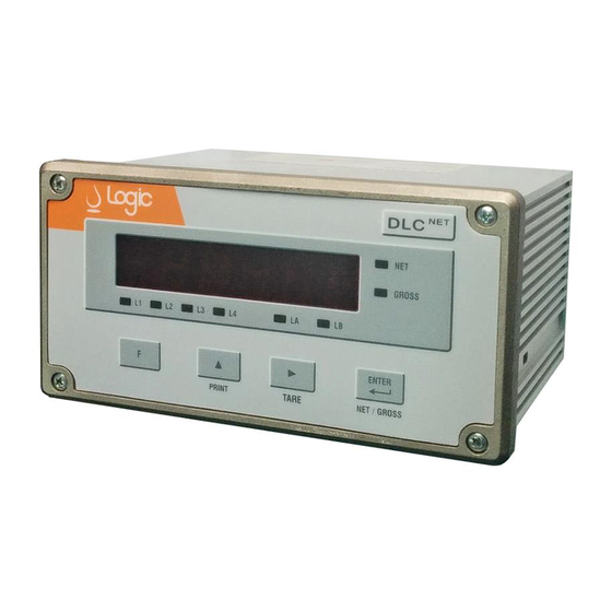
Page 43: Figure 33. Operator Interface Of Dlc
The instruments of DLC series are equipped with keyboard and display for local use of the instrument. They are also compatible with remote displays Logic of DLC3-RD series or, in ® hazardous areas, with BEKA BA488C display. Connection is via RS-485 serial port on board the DLC , as described in paragraph 3.6. -
Page 44: Figure 35. Operator Interface With Beka
Indicator mode: it indicates calibration mode Batch mode: manual dosing component Indicate if the currently displayed weight is gross or net Display 6 digit Weight displaying and name of the menu during parameterization LOGIC S.r.l. - M0145Db.docx Page 44 of 78 Mod. L0006A01 of 30/05/2016... - Page 45 Press to scroll through the list setup options of the instrument. The following menus are available for the setup of the instrument: LOGIC S.r.l. - M0145Db.docx Page 45 of 78 Mod. L0006A01 of 30/05/2016...
- Page 46 Function mode is indicated by the status led If you push the button you can make the temporary tare zeroing of the net weight display. LOGIC S.r.l. - M0145Db.docx Page 46 of 78 Mod. L0006A01 of 30/05/2016...
- Page 47 The procedure described as must always be performed when you change the full scale of the balance. 5.4.2 Access to the calibration menu Follow the instructions in section 5.3. LOGIC S.r.l. - M0145Db.docx Page 47 of 78 Mod. L0006A01 of 30/05/2016...
- Page 48 To maximize accuracy, it is recommended to apply a sample weight as close as possible to the full scale and in any case not less than 50% of the same. LOGIC S.r.l. - M0145Db.docx Page 48 of 78 Mod. L0006A01 of 30/05/2016...
- Page 49 The next data is the capacity of the load cells ( ). Press start editing. Use the buttons to increase the digit and move to the next. Press to confirm. LOGIC S.r.l. - M0145Db.docx Page 49 of 78 Mod. L0006A01 of 30/05/2016...
- Page 50 Enter the value of to be reset using the button to increase the digit and to move on to editing the next one. Press confirm. LOGIC S.r.l. - M0145Db.docx Page 50 of 78 Mod. L0006A01 of 30/05/2016...
- Page 51 0 mA if Press to start editing. At this point, the display shows the value of divisions currently set (default: ), and the first digit blinks. LOGIC S.r.l. - M0145Db.docx Page 51 of 78 Mod. L0006A01 of 30/05/2016...
- Page 52 (default ). Use the button to select . Press to confirm. At this point the instrument will show the written and the procedure is finished. LOGIC S.r.l. - M0145Db.docx Page 52 of 78 Mod. L0006A01 of 30/05/2016...
- Page 53 Fieldbus). It is possible set one of the following values: 1, 4, 8, 16, 32, 64. To change the filtering value: LOGIC S.r.l. - M0145Db.docx Page 53 of 78 Mod. L0006A01 of 30/05/2016...
- Page 54 To change it use the button until the desired item is not displayed. Press to confirm. At this point the instrument will show the letters and the procedure is finished. LOGIC S.r.l. - M0145Db.docx Page 54 of 78 Mod. L0006A01 of 30/05/2016...
- Page 55 To change it use the button until the desired item is not displayed. Press to confirm. At this point the instrument will show the letters and the procedure is finished. LOGIC S.r.l. - M0145Db.docx Page 55 of 78 Mod. L0006A01 of 30/05/2016...
- Page 56 Once editing is complete press to confirm hours and minutes. The display will show . Press to start editing the month and day. LOGIC S.r.l. - M0145Db.docx Page 56 of 78 Mod. L0006A01 of 30/05/2016...
- Page 57 Move through the menu by pressing the button until the menu and press to enter the menu. Enter any password (if set) and press to confirm. LOGIC S.r.l. - M0145Db.docx Page 57 of 78 Mod. L0006A01 of 30/05/2016...
- Page 58 … ), press to start editing. The first digit will start flashing Press to increase the digit and to move to the next. Press to confirm. LOGIC S.r.l. - M0145Db.docx Page 58 of 78 Mod. L0006A01 of 30/05/2016...
- Page 59 USE AND MAINTENANCE MANUAL – DLC Series Use as interface with indicator Press to exit and return to the previous menu. LOGIC S.r.l. - M0145Db.docx Page 59 of 78 Mod. L0006A01 of 30/05/2016...
- Page 60 USE AND MAINTENANCE MANUAL – DLC Series Use as interface with indicator BLANK PAGE LOGIC S.r.l. - M0145Db.docx Page 60 of 78 Mod. L0006A01 of 30/05/2016...
-
Page 61: Figure 36. Application Of The Instrument As A Batcher
, by following the instructions in paragraph 5.5.2. 6.1.2 Dosing control The application of the system is that shown in Figure 36. Figure 36. Application of the instrument as a batcher LOGIC S.r.l. - M0145Db.docx Page 61 of 78 Mod. L0006A01 of 30/05/2016... -
Page 62: Figure 37. Timing Activation Outputs For The Dosing Of Automatic Components
Instant output for solenoid valve Delayed output for pump control The output logic is described in Figure 37. Figure 37. Timing activation outputs for the dosing of automatic components Specifically, the outputs are controlled in the following sequence: ... - Page 63 In that case of operator error the valves and pumps could be inadvertently commanded and it may cause of spills of product. LOGIC S.r.l. - M0145Db.docx Page 63 of 78 Mod. L0006A01 of 30/05/2016...
- Page 64 Not consecutive macroscopic errors (more than twice the amount set in flight) are ignored. To enable the auto-correction: Enter the menu as described in paragraph 5.3.2. Scroll through the button until the menu Press to enter. LOGIC S.r.l. - M0145Db.docx Page 64 of 78 Mod. L0006A01 of 30/05/2016...
- Page 65 Press to enter. Press at any time to cancel and return to the previous menu. The display will show the value currently set (default ). LOGIC S.r.l. - M0145Db.docx Page 65 of 78 Mod. L0006A01 of 30/05/2016...
- Page 66 Batch start time (date / time start of the first dosing) First automatic/manual dosing component and actual value Last automatic/manual dosing component and actual value Batch end time (date / time press button). LOGIC S.r.l. - M0145Db.docx Page 66 of 78 Mod. L0006A01 of 30/05/2016...
- Page 67 Set the in flight amount in way that compensates for the amount of product that flows after the valve has been closed and still not weighted. For more details on the logic operation see also paragraph 6.1.2. In the case where the auto-correction of the amount of flight (...
- Page 68 After changing the parameter, press At this point the instrument will show and the procedure is finished. LOGIC S.r.l. - M0145Db.docx Page 68 of 78 Mod. L0006A01 of 30/05/2016...
- Page 69 Maximum scale capacity ( , see section 6.2.2) If either one of the two conditions is not verified, appears on the screen, according to the fault detected. Make the LOGIC S.r.l. - M0145Db.docx Page 69 of 78 Mod. L0006A01 of 30/05/2016...
- Page 70 If the checks are positive, the instrument gives consent to the dosage and appropriately controls the valves according to the pre-action parameters ) and in flight amount ( ) set and the logic described in paragraph 6.1.2. The product begins to flow and the weight indicator in the display begins to increase.
- Page 71 6.4.5 Recipe printing ( command allows you to print the recipe as specified in paragraph 6.2.5 active or not). To command a print: LOGIC S.r.l. - M0145Db.docx Page 71 of 78 Mod. L0006A01 of 30/05/2016...
- Page 72 The printer memory is erased, all the leds are turned off and you can start a new recipe. If you make abort during a dosage of automatic components, put before pause by pressing LOGIC S.r.l. - M0145Db.docx Page 72 of 78 Mod. L0006A01 of 30/05/2016...
- Page 73 For disassembly of the various components will eventually contact the Manufacturer. As regards the components that require disposal procedures must be followed to the regionally established regulations. LOGIC S.r.l. - M0145Db.docx Page 73 of 78 Mod. L0006A01 of 30/05/2016...
- Page 74 USE AND MAINTENANCE MANUAL – DLC Series Decommissioning and dismantling INTENTIONALLY BLANK PAGE LOGIC S.r.l. - M0145Db.docx Page 74 of 78 Mod. L0006A01 of 30/05/2016...
-
Page 75: Table Of Contents
Figure 31. Hardware setting for Siemens PLC ......................40 Figure 32. Reading instrument with PLC ........................42 Figure 33. Operator interface of DLC instrument ....................43 Figure 34. Operator interface with Logic DLC3-RD ....................43 ® Figure 35. Operator interface with BEKA BA488C ....................44 Figure 36. - Page 76 USE AND MAINTENANCE MANUAL – DLC Series FIGURES INTENTIONALLY BLANK PAGE LOGIC S.r.l. - M0145Db.docx Page 76 of 78 Mod. L0006A01 of 30/05/2016...
- Page 77 Table 4. Load cells connection ........................... 21 Table 5. Connection to the junction box JBOX-V3(EX1) .................... 23 Table 6. Connection of remote display for safe area Logic DLC3-RD ............... 25 Table 7. Serial port parameters for communication with Logic DLC3-RD ..............26 ®...
- Page 78 USE AND MAINTENANCE MANUAL – DLC Series TABLES INTENTIONALLY BLANK PAGE LOGIC S.r.l. - M0145Db.docx Page 78 of 78 Mod. L0006A01 of 30/05/2016...
Need help?
Do you have a question about the DLC NET Series and is the answer not in the manual?
Questions and answers
Hello,I was attempting to calibrate the DLC3 digital load cell interface, and I believe I may have pressed the wrong button during the process. Since then, the screen has started blinking continuously and does not stop unless I disconnect the Profibus cable leading to the PLC. However, once I reconnect the Profibus cable, the blinking resumes. Could you please assist me in resolving this issue?
To resolve the continuous blinking issue on the Logic DLC3 digital load cell interface after incorrect calibration, perform the following steps:
1. Enter the calibration menu.
2. Use one of the supported calibration methods:
- Calibration with sample weights.
- Calibration with a load cell simulator.
- Automatic calibration using known load cell parameters.
- Correction of the zero value.
- Correction of the full scale value.
3. Follow the menu instructions to correctly calibrate the instrument.
Proper calibration should stop the continuous blinking caused by prior incorrect calibration.
This answer is automatically generated
I need DLC3 indicator service manual for calibration
The service manual for calibration of the Logic DLC NET Series DLC3 indicator is the "Use and Maintenance Manual – DLCNET Series" by LOGIC S.r.l.. The calibration procedure is described in Section 5.2 Electrical Calibration of the manual, starting on Page 44 of 78.
This answer is automatically generated