Table of Contents

Related Manuals for Extron electronics Matrix 12800 Series


Summary of Contents for Extron electronics Matrix 12800 Series
- Page 1 Vertrieb von CAMBOARD Electronics Matrix 12800 Series Matrix 12800 Wideband, Video, Sync, or Audio Switchers 68-556-01 Rev. A Printed in the USA 04 04 www.camboard.de Tel. 07131 911201 ce-info@camboard.de Fax 07131 911203...
- Page 2 im Vertrieb von CAMBOARD Electronics Precautions Safety Instructions • English Warning This symbol is intended to alert the user of important operating and maintenance Power sources • This equipment should be operated only from the power source indicated on the product.
-
Page 3: Table Of Contents
im Vertrieb von CAMBOARD Electronics Table of Contents Chapter 1 • Introduction ....................... 1-1 About the Matrix 12800 Switchers ................1-2 Features ........................... 1-4 Definitions ..........................1-8 Chapter 2 • Installation ......................2-1 Installation Overview ....................... 2-2 Rack Mounting the Switcher .................. - Page 4 im Vertrieb von CAMBOARD Electronics Table of Contents, cont’d Subnet Mask field ....................3-25 Date field ......................3-25 Time (GMT) field ....................3-26 ................3-27 Administrator Password field User Password field ....................3-27 ................... 3-27 Mail Server IP Address field ..................
- Page 5 im Vertrieb von CAMBOARD Electronics Password field ......................5-8 E-mail Address fields ..................... 5-8 File Management Page ....................5-8 Set and View Ties Page ....................5-9 Creating a tie ........................5-10 RGBHV Settings page ...................... 5-10 Changing the input gain and attenuation (systems with audio BMEs) ......
- Page 6 im Vertrieb von CAMBOARD Electronics Table of Contents, cont’d Appendix A • Ethernet Connection ................A-1 Ethernet Link ........................A-2 Ethernet connection ......................A-2 Subnetting — A Primer ....................A-2 Gateways ........................... A-3 Local and remote devices ....................A-3 IP address and subfields ....................A-3 Subnet masks and subfields .....................
-
Page 7: Chapter 1 • Introduction
im Vertrieb von CAMBOARD Electronics Matrix 12800 Switchers Chapter One Introduction About the Matrix 12800 Switchers Features Definitions www.camboard.de Tel. 07131 911201 ce-info@camboard.de Fax 07131 911203... -
Page 8: About The Matrix 12800 Switchers
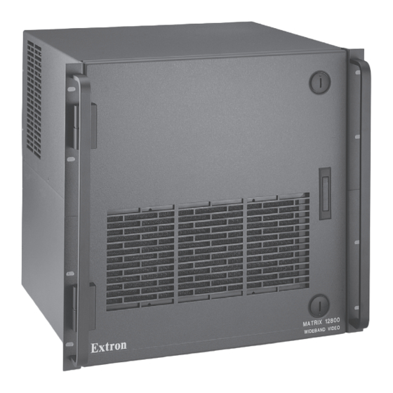
Introduction, cont’d About the Matrix 12800 Switchers The Extron Matrix 12800 Series of switchers is a family of matrix switcher basic module enclosures (BMEs) and an optional front panel controller (FPC 5000) that allows you to create an video and/or audio matrix system with up to 128 inputs and 128 outputs specifically tailored to meet your requirements. - Page 9 im Vertrieb von CAMBOARD Electronics FPC 5000 COM4 COM3 COM2 COM1 AC 100V-230V INPUT Computer Matrix 12800 Wideband Video INPUTS OUTPUTS OUTPUTS Projector CPU STATUS PRIMARY REDUNDANT ADDRESS SYNC POWER SUPPLIES +V -V PRIMARY REDUNDANT PRIMARY AC REDUNDANT AC POWER INPUT POWER INPUT ANAHEIM, CA MADE IN USA...
-
Page 10: Features
im Vertrieb von CAMBOARD Electronics Introduction, cont’d Features Input and output connectors — All connectors are clearly labeled as either input or output for easy installation. With Extron’s virtualization/control software, a visual map can be printed for easy representation of the virtual I/Os. This feature reduces the time required for setup and programming. - Page 11 im Vertrieb von CAMBOARD Electronics Operational flexibility — Operations such as input/output selection, setting of presets, and adjustment of audio levels can be performed at the front panel controller, over the primary and secondary RS-232/RS-422 links, or via the Ethernet link. The RS-232/RS-422 links allow remote control via two PCs or control systems.
- Page 12 im Vertrieb von CAMBOARD Electronics Introduction, cont’d Operational reliability — The Matrix 12800 can support round-the-clock operation in mission-critical applications, using a combination of self-diagnosis, hot- swappable components, and optional redundant components. • Advanced computer-aided diagnostics — The Matrix 12800 performs self diagnostics, 24 hours a day, of the I/O boards, primary and redundant power supply voltages, controller boards, cooling status, and the overall functional status of the matrix.
- Page 13 Channel to channel isolation — The Matrix 12800 Series provides excellent isolation between channels and extremely low electromagnetic emissions — perfect for minimizing signal leakage in high security or government environments.
-
Page 14: Definitions
im Vertrieb von CAMBOARD Electronics Introduction, cont’d Definitions The following terms apply to Extron Matrix Switchers, and are used throughout this manual: Tie — An input-to-output connection. Set of ties — An input tied to two or more outputs. (An output can never be tied to more than one input.) Configuration —... -
Page 15: Chapter 2 • Installation
im Vertrieb von CAMBOARD Electronics Matrix 12800 Switchers Chapter Two Installation Installation Overview Rack Mounting the Switcher Initial Rear Panel Connections and Settings Virtualization/Control Software Post-Virtualization Connections www.camboard.de Tel. 07131 911201 ce-info@camboard.de Fax 07131 911203... -
Page 16: Installation Overview
im Vertrieb von CAMBOARD Electronics Installation Installation, cont’d Installation Overview The Matrix 12800 BMEs that make up a Matrix 12800 system can be installed in a rack or a cabinet, if desired. Each BME must be connected on a daisy chain to the other BMEs in the system and cannot be separated from the other BMEs by more than 25 feet (7.6 m). -
Page 17: Rack Mounting The Switcher
im Vertrieb von CAMBOARD Electronics Rack Mounting the Switcher The Matrix 12800 sync, wideband video, video, and audio BMEs are rack- mountable, 10U high, 17.5" wide (19" wide, including rack ears) metal enclosures. The appropriate rack mounting kit is included with the switcher. Rack mount the switcher as follows: Insert the switcher into the rack, align the holes in the mounting bracket with those of the rack. - Page 18 im Vertrieb von CAMBOARD Electronics Installation, cont’d BME address switch — Each BME must be set to a unique address of 0 through 8. Address 9 is invalid. The addresses used in the system must be sequential with no skipped numbers, other than as required for audio BMEs. Audio BMEs occupy two BME addresses: the set address and the set address plus 1 (for example, if the audio BME is set to address 3, it occupies addresses 3 and 4).
- Page 19 im Vertrieb von CAMBOARD Electronics BME COMM interconnect ports — If the Matrix 12800 system consists of more than one BME, the BMEs must be connected together in a daisy chain using Extron-supplied RJ-45 cables. Connect the first daisy chain from BME 0’s BME Comm Out connector to the nearest BME’s BME Comm In connector (figure 2-3).
- Page 20 im Vertrieb von CAMBOARD Electronics Installation, cont’d Primary and Secondary RS-232/RS-422 ports — For systems consisting of a single switcher or for BME 0 on a multi-BME system, connect host devices (such as computers or touch panel control systems) or MCP 1000 remote control panels (refer to the MCP 1000 Remote Control Panel User’s Manual) to the Primary and Secondary RS-232/RS-422 ports (figure 2-4).
- Page 21 im Vertrieb von CAMBOARD Electronics Primary and Redundant AC Power Input connectors — Connect a standard IEC power cord between the rear panel Primary AC Power Input connector and a 100 to 240VAC, 50 Hz or 60 Hz power source (figure 2-6). T A T CPU STATUS IM A...
-
Page 22: Virtualization/Control Software
Help) into a group or folder named “Extron Electronics”. Starting the software Click Start>Programs > Extron Electronics > Matrix 6400+12800 Control Program to start the program. You will be asked to select the appropriate Comm port or Ethernet port, or to select Emulate mode. After you select the Comm or Ethernet port, the software looks for the Matrix system, reads its configuration, and then displays it in the Extron’s Matrix 12800 Control Program window. -
Page 23: Post-Virtualization Operations
im Vertrieb von CAMBOARD Electronics Post-Virtualization Operations Wideband and sync connections (wideband, video, and sync BMEs only) Wideband and sync input and output connectors — Use worksheets and/or printouts from the Matrix 12800 System/Virtualization Control program to determine the virtual connection on each physical input and output connection. - Page 24 im Vertrieb von CAMBOARD Electronics Installation, cont’d Balanced and unbalanced audio input connectors — Each input has a 3.5 mm, 5-pole captive screw connector for balanced or unbalanced stereo audio input. Connectors are included with each Matrix 12800 audio switcher, but you must supply the audio cable.
-
Page 25: Remote Control Panel And Front Panel Controller/Ethernet Connections
im Vertrieb von CAMBOARD Electronics Audio outputs connectors — These 3.5 mm, 5-pole captive screw connectors output the selected unamplified, line level audio. Connect audio devices, such as an audio amplifier or powered speakers. See figure 2-10 to properly wire an output connector. Ring See caution Sleeve... -
Page 26: Cabling And Rj-45 Connector Wiring
im Vertrieb von CAMBOARD Electronics Installation, cont’d Ethernet port — For systems consisting of a single switcher or for BME 0 on a multi-BME system, if desired connect the Matrix 12800 either directly to an FPC 5000 Front Panel Controller or to an Ethernet LAN via this RJ-45 connector (figure 2-12). - Page 27 im Vertrieb von CAMBOARD Electronics Patch (straight) cable Side 1 Side 2 Wire color Wire color White-orange White-orange Side Clip Down Orange Orange Pins 2 3 4 5 6 7 8 RJ-45 White-green White-green connector Blue Blue White-blue White-blue Green Green White-brown White-brown...
-
Page 28: External Sync Connections (Wideband And Video Bmes Only)
im Vertrieb von CAMBOARD Electronics Installation, cont’d External sync connections (wideband and video BMEs only) For NTSC/PAL/SECAM video, when the switcher switches between inputs, the resulting change in image should be seamless, or clean. The Matrix 12800 switcher can use an external signal to synchronize switching during the vertical interval. Without the external sync locking feature, switching between inputs can result in a brief rolling (sync loss) or a brief change in the picture size. -
Page 29: Serial Port Protocol Switches
im Vertrieb von CAMBOARD Electronics Figure 2-15 shows another configuration, in which the timing source passes through three video cameras and a video scan converter before connecting to the switcher. This type of video camera is capable of synchronizing with the external timing source for video editing applications. -
Page 30: Sync Termination Switches
im Vertrieb von CAMBOARD Electronics Installation, cont’d Sync termination switches Each input board supports 32 (two columns on the back panel) physical inputs. In a sync BME, the first eight physical inputs on each input board are equipped with sync termination DIP switches. Each switch provides the option of selecting either 510 ohms or 75 ohms. - Page 31 im Vertrieb von CAMBOARD Electronics Matrix 12800 Switchers Chapter Three Virtualization/Control Software Explaining Virtual I/O Switching Virtualization/Control Program Special Characters www.camboard.de Tel. 07131 911201 ce-info@camboard.de Fax 07131 911203...
-
Page 32: Chapter 3 • Virtualization/Control Software
im Vertrieb von CAMBOARD Electronics Virtualization/Control Software Virtualization/Control Software, cont’d Explaining Virtual I/O Switching A Matrix 12800 system consists of from one to nine BMEs, each of which can have as many as 128 inputs and 128 outputs. It is usually desirable to have certain inputs switch together as a set, to follow each other. - Page 33 im Vertrieb von CAMBOARD Electronics The largest possible system consists of three 128 x 128 video BMEs, two 128 x 128 sync BMEs, and one 128 x 128 audio BME. This system can then be mapped to become a matrix with 128 virtual inputs and 128 virtual outputs in seven virtual planes (R, G, B, H, V, left-channel audio, and right-channel audio).
-
Page 34: Virtualization/Control Program
im Vertrieb von CAMBOARD Electronics Virtualization/Control Software, cont’d Virtualization/Control Program The Extron-supplied Matrix 12800/6400/3200 Virtualization/Control software runs in a Windows-type computer and communicates with the matrix switcher via the primary or secondary RS-232/RS-422 ports or the Ethernet port on BME 0. The software provides an easy way for you to virtualize the matrix switcher and to establish rooming presets. -
Page 35: Creating A Virtual I/O Switching System (Map)
PC and the Primary RS-232/RS-422 port on BME 0. Power up the Matrix 12800 system. See chapter 2, Installation. On the PC, click Start>Programs>Extron Electronics>Matrix 6400+12800 Control Program to start the program. The Comm Port Selection window (figure 3-1) appears. - Page 36 im Vertrieb von CAMBOARD Electronics Virtualization/Control Software, cont’d After you select the Comm port and click OK, the software looks for the Matrix system and reads its hardware configuration, the type and size of each BME. The software then reads all of the current settings, such as the ties, presets, and virtual map, and displays a graphical representation of the ties in the program window (figure 3-2).
- Page 37 im Vertrieb von CAMBOARD Electronics On the menu bar, click System-Config to show the Virtual Map screen (figure 3-3). Figure 3-3 — Virtual Map screen www.camboard.de Tel. 07131 911201 ce-info@camboard.de Matrix 12800 Switchers • Virtualization/Control Software Fax 07131 911203...
- Page 38 im Vertrieb von CAMBOARD Electronics Virtualization/Control Software, cont’d On the menu bar, click Configure>Physical Switchers to show the Physical Configuration screen (figure 3-4). Check this screen to ensure that all BMEs were seen on program startup and that their type and size is reported correctly. Click the Close button to return to the Virtual Map screen.
- Page 39 im Vertrieb von CAMBOARD Electronics If a sync BME was found, you can specify, in the Sync Config box, whether the Virtualization/Control program is to map the system using Composite sync (one plane) or Separate H + V sync (two planes). In the Ordering box, you can specify whether the program is to organize the map assignments in a repeating pattern or grouped by plane.
-
Page 40: Reassigning Virtual I/O Connectors
im Vertrieb von CAMBOARD Electronics Virtualization/Control Software, cont’d If desired, on the Virtual Map screen menu bar, click Print Maps to create a hard copy map of the virtual system. If you send the map to a color printer (select the printer by clicking on File>Select printer on the main screen), the map prints with the red plane mapped in red, the green plane in green, the blue plane in blue, the horizontal plane in black, the vertical plane in yellow, and the audio plane in olive. - Page 41 im Vertrieb von CAMBOARD Electronics Figure 3-6 — Virtual map and list fields of Virtual Map screen Map an unused connector to replace a current connector on the Virtual Map screen as follow: Click the Edit Mode box to enable mapping. Click and begin dragging the unused connector.
-
Page 42: Creating Rooms Within The System
(see Creating a virtual I/O switching system (map) in this chapter). On the PC, click Start>Programs>Extron Electronics>Matrix 12800 Control Program to start the program. You will be asked to select the appropriate PC Comm port or the Ethernet port or to select Emulate mode (figure 3-1). - Page 43 im Vertrieb von CAMBOARD Electronics If you clicked Emulate to create a program for a system in advance without being connected to it, you will have to define the number and type (video, sync, or audio) of BMEs, the number of inputs, and the number of outputs for the Matrix 12800 system you are emulating.
-
Page 44: Remote Controlling The Matrix 12800 System
(see Creating a virtual I/O switching system (map) in this chapter). On the PC, click Start>Programs>Extron Electronics>Matrix 12800 Control Program to start the program. You will be asked to select the appropriate PC Comm port or the Ethernet port or to select Emulate mode (figure 3-1). -
Page 45: Ties
im Vertrieb von CAMBOARD Electronics Ties Ties appear as solid lines in various colors on the Virtualization/Control program’s main screen. The different colors indicate different follow and breakaway configurations. If both video and audio are tied, the tie is indicated in blue. If video only is tied, the tie is indicated in magenta. -
Page 46: Presets
im Vertrieb von CAMBOARD Electronics Virtualization/Control Software, cont’d Presets After you have created all of the ties that will be needed for a specific task, the configuration can be saved as either a global or room preset. The Matrix 12800 can support up to 64 global presets and up to 10 room presets in each of up to 32 rooms. -
Page 47: Icons And Captions
im Vertrieb von CAMBOARD Electronics Icons and captions For your convenience, you can assign a device icon and/or a name to any of the virtual inputs or outputs using the devices palette. The icons are saved by the program, not sent to the switcher. To access the Devices screen (figure 3-11), right-click the desired I/O port or on the menu bar click Tools>Assign Device Icons. -
Page 48: Programming The Matrix Offline (Emulate Mode)
Lastly, emulation mode allows you to program a hardware configuration that differs from the current configuration. On the PC, click Start>Programs>Extron Electronics>Matrix 12800/6400/3200 Control Program to start the program. When prompted for a port, select Emulate (figure 3-12) and click OK. - Page 49 im Vertrieb von CAMBOARD Electronics If you have not virtualized the system represented by your startup file, the Virtual Configuration screen appears (figure 3-5). This screen shows how the software has mapped the physical system into a virtual system. There are several variables that you can change on this screen that affect the number of virtual planes and inputs and outputs that are available and how they are presented.
-
Page 50: Saving And Restoring Matrix Settings
im Vertrieb von CAMBOARD Electronics Virtualization/Control Software, cont’d Saving and restoring matrix settings In on-line (as opposed to emulation mode) operation, the Virtualization/Control program reads the source file, Mtrx12800.ini, upon startup. The program reads the file to display the icons, because these items do not cause any changes in the system configuration (programming) and provide convenience to the user. -
Page 51: Creating Program Byte Strings
im Vertrieb von CAMBOARD Electronics Creating program byte strings The Matrix 12800 system can be controlled and programmed from a third-party control system, via the RS-232/RS-422 port. The control systems need to be taught what bytes to send to the system to communicate with the Matrix system. Chapter 4 of this manual, Programmer’s Guide, details the Extron Simple Instruction Set (SIS and Advanced Instruction Set (AIS) and how to build these byte strings using a pencil and paper. -
Page 52: Logging On To The Switcher Via The Ethernet
CAMBOARD Electronics Virtualization/Control Software, cont’d Logging on to the switcher via the Ethernet On the PC, click Start>Programs>Extron Electronics>Matrix 12800/6400/3200 Control Program to start the program. When prompted for a port, select IP [LAN] (figure 3-14) and click OK. Figure 3-14 — Ethernet mode selection The IP connection window appears (figure 3-15). -
Page 53: Ethernet Protocol Settings
im Vertrieb von CAMBOARD Electronics Ethernet protocol settings The IP settings/options screen (figure 3-16) provides a location for observing and, if connected via the RS-232/422 link or if logged on via the Ethernet port as an administrator, editing settings unique to the Ethernet interface. Access this screen by clicking Tools >... -
Page 54: Extron Ip Address Field
im Vertrieb von CAMBOARD Electronics Virtualization/Control Software, cont’d Extron IP Address field The Extron IP Address field contains the IP address of the connected BME. This value is encoded in the flash memory on the primary and redundant controller circuit boards. Valid IP addresses consist of four 1-, 2-, or 3-digit numeric subfields separated by dots (periods). -
Page 55: Gateway Ip Address Field
im Vertrieb von CAMBOARD Electronics Gateway IP Address field The Gateway IP Address field identifies the address of the gateway to the mail server to be used if the Matrix 12800 and the mail server are not on the same subnet. -
Page 56: Time (Gmt) Field
im Vertrieb von CAMBOARD Electronics Virtualization/Control Software, cont’d Time (GMT) field The Time field displays the current time in the Greenwich Mean Time zone. If necessary, adjust the time as follows: Click the mouse in the Time field. A set time field appears with the time in the 24-hour format HH:MM:SS (00:00:00 to 23:59:59). -
Page 57: User Password Field
im Vertrieb von CAMBOARD Electronics User Password field The User Password field displays the password required to log on to the Matrix 12800 via the Ethernet port as a user, without all of the administrator’s rights and privileges. Passwords are case sensitive and are limited to 12 upper case and lower case alphanumeric characters. -
Page 58: Mail Server Password Field
im Vertrieb von CAMBOARD Electronics Virtualization/Control Software, cont’d Mail Server Password field The Mail Server Password field displays the password that the Matrix 12800 uses to log on to the e-mail server. Passwords are case sensitive and are limited to 12 upper case and lower case alphanumeric characters. -
Page 59: Windows Buttons And Drop Boxes
im Vertrieb von CAMBOARD Electronics Windows buttons and drop boxes The buttons and drop boxes on the right side of the program window perform the following functions: RGB Mute — Toggles the video mute on and off. Audio Mute — Toggles the audio mute on and off. Room menu —... - Page 60 im Vertrieb von CAMBOARD Electronics Virtualization/Control Software, cont’d Tools menu — Edit/view Config — Displays the Virtual Map screen, which graphically presents the virtual map and allows you to make changes to the map. List Remote Keypads — List Remote Keypads shows the status of all possible MKP 1200 Remote Keypads.
- Page 61 im Vertrieb von CAMBOARD Electronics Preferences menu — Immediate changes — Causes changes to take effect immediately. Hold/verify changes — Delays implementation of changes until the Changes – Take button is pressed. Show all tie-lines — Causes the main screen to display all ties at once, as shown in figure 3-2.
-
Page 62: Virtual Map Screen Menu Bar Options
im Vertrieb von CAMBOARD Electronics Virtualization/Control Software, cont’d Ties as crosspoints — Displays ties as a matrix of inputs and outputs (figure 3-20). Made ties are indicated as blue (video and audio) boxes or boxes of the applicable color for each video plane. Ties that will take effect when you click on the Take button are indicated by +. -
Page 63: Special Characters
im Vertrieb von CAMBOARD Electronics Special Characters Certain characters are reserved for specific functions. The switcher will not accept these characters as part of preset names, the switcher’s name, passwords, or locally created file names. The switcher rejects the following characters: {space} ~ @ = ‘... - Page 64 im Vertrieb von CAMBOARD Electronics Virtualization/Control Software, cont’d www.camboard.de Tel. 07131 911201 ce-info@camboard.de 3-34 Matrix 12800 Switchers • Virtualization/Control Software Fax 07131 911203...
-
Page 65: Chapter 4 • Programmer's Guide
im Vertrieb von CAMBOARD Electronics Matrix 12800 Switchers Chapter Four Programmer’s Guide RS-232/422 Link Ethernet Link Host-to-Switcher Instructions Switcher-Initiated Messages Switcher Error Responses Using the Command/Response Table Command/Response Table for SIS Commands www.camboard.de Tel. 07131 911201 ce-info@camboard.de Fax 07131 911203... -
Page 66: Ethernet Link
im Vertrieb von CAMBOARD Electronics Programmer’s Guide Programmer’s Guide, cont’d RS-232/RS-422 Link The rear panel RS-232/RS-422 connectors (figure 4-1) of the matrix switcher BME 0 can be connected to the serial port output of a host device such as a computer running the HyperTerminal utility or a control system. -
Page 67: Host-To-Switcher Instructions
The switcher-initiated messages are listed below (underlined). (C) Copyright 2003, Extron Electronics Matrix12800, Vx.xx,date/time, The copyright message is initiated by the switcher when it is first powered on. Vx.xx is the firmware version number. -
Page 68: Switcher Error Responses
im Vertrieb von CAMBOARD Electronics Programmer’s Guide, cont’d Login Administrator Login User The switcher initiates the login message when a correct administrator or user password has been entered. If the user and administrator passwords are the same, the switcher defaults to administrator privileges. All Configuration Memory Cleared The memory cleared message is initiated by the switcher when a system reset has occurred. -
Page 69: Symbols
im Vertrieb von CAMBOARD Electronics Symbols Input and output numbers in commands may be entered as either 1-, or 2-, or 3-digit numbers. All input and output numbers are specified as 3-digit numbers in the response. = Carriage return/line feed = Carriage return (no line feed) •... -
Page 70: Command/Response Table For Sis Commands
im Vertrieb von CAMBOARD Electronics Programmer’s Guide, cont’d = GMT date and time (MM/DD/YY•HH:MM:SS [Example: 11/09/01•14:52:36]) = Keypad mode: 001 = output mode, 002 = global preset mode, 003 = room preset mode = Keypad variable: output number if = output mode, room number if = room mode, meaningless if = global preset mode... - Page 71 im Vertrieb von CAMBOARD Electronics Command/response table for SIS commands (Cont’d) Command ASCII Command Response Additional description (host to switcher) (switcher to host) Preset commands (continued) Recall a room preset •Rpr Command character is a period. If the preset is unassigned, then the name displays [unassigned]. If the preset is saved, but not yet named, the default name is Preset If the room preset is saved, but not yet named, the default name is Rm Prst...
- Page 72 im Vertrieb von CAMBOARD Electronics Programmer’s Guide, cont’d Command/response table for SIS commands (Cont’d) Command ASCII Command Response Additional description (host to switcher) (switcher to host) View commands View video output tie Example Output 5 video tied to input 7. View audio output tie Example: Output 12 video tied to input 8.
- Page 73 im Vertrieb von CAMBOARD Electronics Command/response table for SIS commands (Cont’d) Command ASCII Command Response Additional description (host to switcher) (switcher to host) View commands (continued) The response to the View File Directory command differs, depending on whether the command is sent via an RS- 232/RS-422 or Telnet connection or sent via a Web browser connection.
- Page 74 im Vertrieb von CAMBOARD Electronics Programmer’s Guide, cont’d Command/response table for SIS commands (Cont’d) Command ASCII Command Response Additional description (host to switcher) (switcher to host) Names (continued) Read room name Esc X8 Write virtual input name ,nameNI ,name Esc X1 Read virtual input name Esc X1 Write virtual output name...
- Page 75 im Vertrieb von CAMBOARD Electronics Command/response table for SIS commands (Cont’d) Command ASCII Command Response Additional description (host to switcher) (switcher to host) Information commands (continued) Information request, specific BME •T •U •M ECHNOLOGY OF UNITS N MAP SIZE UT MAP SIZE Example: 128X128•T1•U3•M64X64 In the example above, 128X128 indicates that this BME has 128 physical inputs and 128 physical outputs.
- Page 76 im Vertrieb von CAMBOARD Electronics Programmer’s Guide, cont’d www.camboard.de Tel. 07131 911201 ce-info@camboard.de 4-12 Matrix 12800 Switchers • Programmer’s Guide Fax 07131 911203...
-
Page 77: Chapter 5 • Web Operation
im Vertrieb von CAMBOARD Electronics Matrix 12800 Switchers Chapter Five Web Operation Download the Startup Page System Status Page System Configuration Page File Management Page Set and View Ties Page Physical Connections Pages www.camboard.de Tel. 07131 911201 ce-info@camboard.de Fax 07131 911203... -
Page 78: Download The Startup Page
im Vertrieb von CAMBOARD Electronics Web Operation Web Operation, cont’d The Matrix 12800 can be controlled and operated through the Ethernet port on BME 0, across the LAN or WAN, using a Web browser, such as Microsoft’s Internet Explorer. The browser down loads a series of displays that have the appearance of Web pages. -
Page 79: System Status Page
im Vertrieb von CAMBOARD Electronics The switcher checks several possibilities, in the following order, and then responds accordingly: Does the address include a specific file name, such as 10.13.156.10/file_name.html? If so, the switcher downloads that HTML page. Is there a file in the switcher’s memory that is named “index.html”? If so, the switcher downloads “index.html”... -
Page 80: Bme Status Page
im Vertrieb von CAMBOARD Electronics Web Operation, cont’d BME Status page To observe more status details for a specific BME, from the System Status page, click the BME number, either at the top of the status column or in the brackets to the left of the screen. -
Page 81: Dsvp Page
im Vertrieb von CAMBOARD Electronics DSVP page To observe the Digital Sync Validation Processing (DSVP) for an input, from the System Status page, click the DSVP link to the left of the screen (figure 5-5). DSVP is only available in systems that include a sync BME. Select System Status Refresh... -
Page 82: Administration Fields
im Vertrieb von CAMBOARD Electronics Web Operation, cont’d Administration fields • Ethernet connection to the Matrix switcher, either entering SIS commands (see chapter 4, Programmer’s Guide), using the Matrix 12800/6400/3200 Control Program (see chapter 3, Virtualization/Control Software), or using HTML pages, is password protected. •... -
Page 83: Hardware Address Field
im Vertrieb von CAMBOARD Electronics Hardware Address field The Hardware Address field is hardcoded on the primary controller board in BME 0 and cannot be changed. Email Settings page The Email Settings page (figure 5-7) can be reached by clicking on the Email Settings link on the system configuration page. -
Page 84: Password Field
im Vertrieb von CAMBOARD Electronics Web Operation, cont’d Password field The mail server Password field and re-enter password field display and confirm the password that the Matrix 12800 uses to log on to the e-mail server. Passwords are case sensitive and are limited to 12 upper case and lower case alphanumeric characters. -
Page 85: Set And View Ties Page
im Vertrieb von CAMBOARD Electronics Set and View Ties Page You can create ties on the Set and View Ties page (figure 5-9). Access the Set and View Ties page by clicking the Control tab. Refresh or Select Different Tie (Output) Groups Select RGBHV Settings Select Global Presets... -
Page 86: Creating A Tie
im Vertrieb von CAMBOARD Electronics Web Operation, cont’d Creating a tie Create a tie as follows: Click on the Video Only, Audio Only, or Video & Audio button to select video, audio, or both for switching (audio follow or audio breakaway). Each mouse click on a button toggles the other two buttons off. -
Page 87: Changing The Input Gain And Attenuation (Systems With Audio Bmes)
im Vertrieb von CAMBOARD Electronics Changing the input gain and attenuation (systems with audio BMEs) Users can set each input’s level of audio gain or attenuation (-18 dB to +24 dB) from the RGBHV Settings page. Audio levels can be adjusted so there are no noticeable volume differences between sources. -
Page 88: Muting And Unmuting One Or All Outputs
im Vertrieb von CAMBOARD Electronics Web Operation, cont’d Muting and unmuting one or all outputs Mute one or all outputs as follows: To select an individual output to mute or unmute, click the Output drop box. A drop-down scroll box appears (figure 5-13). Figure 5-13 —... -
Page 89: Global Presets Page
im Vertrieb von CAMBOARD Electronics Click on the RGB delay drop box. A drop-down scroll box appears (figure 5-15). Figure 5-15 — RGB delay drop box Click on the desired RGB delay. Global Presets Page You can save and recall global presets from the Global Presets page (figure 5-16). Access the Global Presets page by clicking the Global Presets link on the left of the Set and View Ties page. -
Page 90: Saving A Preset
im Vertrieb von CAMBOARD Electronics Web Operation, cont’d Saving a preset Save the current configuration (configuration 0) as a preset as follows: Click the Save Preset button. Select the desired preset by clicking on one of the presets listed. To create a new preset, click the on one of the [unassigned] buttons. -
Page 91: Chapter 6 • Upgrades And Maintenance
im Vertrieb von CAMBOARD Electronics Matrix 12800 Switchers Chapter Six Upgrades and Maintenance Opening and Closing the Matrix Switcher Removing and Installing the Fan Assembly Removing and Installing the Power Supply Module Replacing the Fuse Removing and Cleaning the Filter Setting the DIP Switches Removing and Installing the Controller Board Updating the Firmware... -
Page 92: Opening And Closing The Matrix Switcher
im Vertrieb von CAMBOARD Electronics Upgrades and Maintenance Upgrades and Maintenance, cont’d For proper cooling and air flow, all access doors should be closed during normal switcher operations. Opening and Closing the Matrix Switcher Opening the switcher All maintenance and upgrade procedures require access to the switcher’s interior by opening the front door (figure 6-1). -
Page 93: Closing The Switcher
im Vertrieb von CAMBOARD Electronics Closing the switcher If the door was removed, replace the door by lifting it above the hinge pins and lowering it onto the pins. Shut the door. Turn the bottom door fastener clockwise from Turn the top door fastener counterclockwise from (figure 6-2). -
Page 94: Removing And Installing The Fan Assembly
im Vertrieb von CAMBOARD Electronics Upgrades and Maintenance, cont’d Removing and Installating the Fan Assembly The four fans on the fan assembly door are paired; two primary fans in one assembly and two redundant fans in another assembly (figure 6-3). The two fans in the primary fan assembly share a common power connector and the two fans in the redundant fan assembly share a separate connector. - Page 95 im Vertrieb von CAMBOARD Electronics Remove four nuts w/ captive washers (each fan). Remove screws from cable hold down brackets. Disconnect fans at connectors. Figure 6-4 — Fan pair replacement Using a 5/16" nut driver, remove and retain the four nuts securing each fan to the fan assembly door.
-
Page 96: Removing And Installing The Power Supply Module
im Vertrieb von CAMBOARD Electronics Upgrades and Maintenance, cont’d Removing and Installing the Power Supply Module Removing the power supply module The two or four power supply modules (primary power supplies A and B and optional redundant power supplies A and B) are identical and hot-swappable. Each power supply module has two LEDs, visible when the fan assembly door is open, that indicate the status of the voltages that power supply outputs. -
Page 97: Installing The Power Supply Module
im Vertrieb von CAMBOARD Electronics If a replacement power supply is not being installed immediately, close the fan assembly door and turn the left and right knurled knobs ¼-turn clockwise. Ensure that you close and secure the fan assembly door when you have CAUTION finished this maintenance procedure. -
Page 98: Replacing The Fuse
im Vertrieb von CAMBOARD Electronics Upgrades and Maintenance, cont’d Replacing the Fuse The primary and redundant AC power circuits are independently fused. The fuses are accessible on the rear panel of the switcher. If a fuse opens, the associated primary or redundant power loop will shut down. If this BME does not have redundant power supplies, the switcher will shut down. -
Page 99: Removing And Cleaning The Filter
im Vertrieb von CAMBOARD Electronics Removing and Cleaning the Filter The filter can be removed for cleaning without powering down the CAUTION switcher, but do not operate the switcher without filtering longer than necessary to clean the filter. Remove and clean the air filter as follows: Open the front door. -
Page 100: Setting The Dip Switches
im Vertrieb von CAMBOARD Electronics Upgrades and Maintenance, cont’d Setting the DIP Switches Swapping the serial port protocol (RS-232/RS-422) If this BME is equipped with a redundant controller, the primary and redundant controllers must be configured for the same communications protocol. -
Page 101: Changing The Serial Port Baud Rate
im Vertrieb von CAMBOARD Electronics Changing the serial port baud rate If this BME is equipped with a redundant controller, the primary and redundant controllers must be configured for the same RS-232/RS-422 communications baud rate. The Matrix 12800 controller boards are factory configured for 9600 baud rate on the RS-232/RS-422 port. -
Page 102: Changing The Sync Termination
im Vertrieb von CAMBOARD Electronics Upgrades and Maintenance, cont’d Changing the sync termination In a sync BME, the first eight physical inputs on each I/O board are equipped with sync termination DIP switches. Each switch provides the option of selecting either 510 ohms or 75 ohms. -
Page 103: Removing And Installing The Controller Board
im Vertrieb von CAMBOARD Electronics Removing and Installing the Controller Board Removing the primary or redundant controller board The controller boards are hot-swappable. If this BME has redundant controller boards, either controller board can be removed without powering down the switcher. -
Page 104: Installing The Controller Board
im Vertrieb von CAMBOARD Electronics Upgrades and Maintenance, cont’d Slide the board out of the cardcage. Place the removed board on an anti-static surface or in an anti-static container. If a replacement board is not being installed immediately, close the fan assembly door and turn the left and right knurled knobs ¼-turn clockwise. -
Page 105: Updating The Firmware
im Vertrieb von CAMBOARD Electronics Updating the Firmware If your system has primary and redundant controller boards, both boards must have the same firmware revisions installed. The ICs that contain the firmware for the matrix switcher also contain the memory in which presets and audio levels are saved. When you replace the IC, these settings will be lost. -
Page 106: Removing The I/O Board
im Vertrieb von CAMBOARD Electronics Upgrades and Maintenance, cont’d Removing and Installing the I/O Board The I/O boards are hot-swappable. You do not need to power down the switcher to remove an I/O board. Circuit boards can be replaced for fault correction. Beyond that, you can increase or decrease the I/O configuration (size) of the Matrix 12800 by adding or removing I/O boards and then rerunning the Virtualization/Control Program (see chapter 3, Virtualization/Control software). -
Page 107: Installing The I/O Board
im Vertrieb von CAMBOARD Electronics Ejector Lever Video Card 2 Green LEDs 2 Red LEDs Ejector Lever Open I/O card door. Figure 6-13 — I/O board replacement Installing the I/O board The I/O boards are hot-swappable. You do not need to power down the switcher to install an I/O board. -
Page 108: Troubleshooting
im Vertrieb von CAMBOARD Electronics Upgrades and Maintenance, cont’d Close the I/O cardcage door and turn the left and right knurled knobs ¼-turn clockwise. Close the front door. If this circuit board installation is a permanent change to the size of the matrix, the system will need to virtualized to recognize the change. -
Page 109: Communication With The Fpc 5000
im Vertrieb von CAMBOARD Electronics Communication with the FPC 5000 Symptom Cause Suggested solutions The matrix switcher There is a Check that the FPC 5000 has the correct IP and the FPC 5000 disagreement in the IP address for the Matrix 12800. cannot communicate. - Page 110 im Vertrieb von CAMBOARD Electronics Upgrades and Maintenance, cont’d www.camboard.de Tel. 07131 911201 ce-info@camboard.de 6-20 Matrix 12800 Switchers • Upgrades and Maintenance Fax 07131 911203...
-
Page 111: Ethernet Link
im Vertrieb von CAMBOARD Electronics Matrix 12800 Switchers A ppendix A Ethernet Connection Ethernet Link Subnetting — A Primer Telnet www.camboard.de Tel. 07131 911201 ce-info@camboard.de Fax 07131 911203... - Page 112 im Vertrieb von CAMBOARD Electronics Ethernet Connection Ethernet Connection, cont’d Ethernet Link The rear panel Ethernet connector (figure A-1) on the matrix switcher BME 0 can be connected to the Ethernet LAN or WAN. This connection makes SIS control of the switcher possible using a computer connected to the same LAN.
-
Page 113: Gateways
im Vertrieb von CAMBOARD Electronics Gateways A gateway is a computer that provides a link between different subnets. The e-mail server that the Matrix 12800 uses for e-mail notification can communicate with the e-mail server directly (on the same subnet) or be routed via a gateway. -
Page 114: Determining Whether Devices Are On The Same Subnet
im Vertrieb von CAMBOARD Electronics Ethernet Connection, cont’d Determining whether devices are on the same subnet To determine the subnet, the local device’s IP address is compared to the remote device’s IP address (figure A-4). Each address’s subfields are compared or not compared, depending on the value in the related subnet mask subfield. - Page 115 im Vertrieb von CAMBOARD Electronics C:\>ping 192.168.254.254 Pinging 192.168.254.254 with 32 bytes of data: Reply from 192.168.254.254: bytes=32 time<10ms TTL=128 Reply from 192.168.254.254: bytes=32 time<10ms TTL=128 Reply from 192.168.254.254: bytes=32 time<10ms TTL=128 Reply from 192.168.254.254: bytes=32 time<10ms TTL=128 Ping statistics for 192.168.254.254: Packets: Sent = 4, Received = 4, Lost = 0 (0% loss), Approximate round trip times in milli-seconds: Minimum = 0ms, Maximum = 0ms, Average = 0ms...
-
Page 116: Telnet Tips
im Vertrieb von CAMBOARD Electronics Ethernet Connection, cont’d Telnet tips Open Connect to the Matrix 12800 using the Open command. Once you are connected to the Matrix 12800, you can enter the SIS and AIS the same as you would if you were using the RS-232/422 link. -
Page 117: Set Carriage Return-Line Feed
im Vertrieb von CAMBOARD Electronics Set carriage return-line feed Unless commanded otherwise, Telnet transmits a line feed character only (no carriage return) to the connected Matrix 12800 when you press the key. This is Enter the correct setting for SIS communication with the Matrix 12800. The Telnet set crlf command forces Telnet to transmit carriage return and line feed characters when is pressed, but if crlf is set, the SIS link with the switcher will not function Enter... - Page 118 im Vertrieb von CAMBOARD Electronics Ethernet Connection, cont’d www.camboard.de Tel. 07131 911201 ce-info@camboard.de Matrix 12800 Switchers • Ethernet Connection Fax 07131 911203...
-
Page 119: Appendix B • Reference Information
im Vertrieb von CAMBOARD Electronics Matrix 12800 Switchers A ppendix B Reference Information Specifications Part Numbers www.camboard.de Tel. 07131 911201 ce-info@camboard.de Fax 07131 911203... - Page 120 im Vertrieb von CAMBOARD Electronics Reference Information Reference Information, cont’d Specifications Video — wideband/video BMEs Routing .......... 32 x 16 or larger matrix up to 128 x 128, depending on the configuration Gain ..........Unity Bandwidth Wideband models ....375 MHz (-3 dB), fully loaded 0 MHz to 10 MHz ..
- Page 121 im Vertrieb von CAMBOARD Electronics Input impedance ......Inputs 1 - 32 ....510 ohms or 75 ohms, switchable Inputs 33 - 128 ..510 ohms Output impedance ...... 75 ohms Horizontal frequency ....15 kHz to 150 kHz Vertical frequency ....... 30 Hz to 150 Hz Polarity ..........
- Page 122 im Vertrieb von CAMBOARD Electronics Reference Information, cont’d General Power* ........... 2 (positive-negative), 100VAC to 240VAC, 50/60 Hz; internal, autoswitchable Matrix 12000 wideband ..150 watts at 115VAC, 60 Hz Matrix 12800 sync ....100 watts at 115VAC, 60 Hz Matrix 12800 audio ....
-
Page 123: Matrix 12800 Part Numbers
im Vertrieb von CAMBOARD Electronics Part Numbers Matrix 12800 part numbers Extron part Part # Call Extron for part numbers Optional accessories Extron part Part # FPC 5000 Front Panel Controller 60-503-01 MKP 1200 Gray 60-528-01 Black 60-528-02 White 60-528-03 MCP 1000M (master) 60-298-01 MCP 1000S (slave) -
Page 124: Assorted Connectors
im Vertrieb von CAMBOARD Electronics Reference Information, cont’d Assorted connectors BNC connectors Part # BNC Mini HR crimp connectors, qty. 50 100-074-51 SHRmale crimp connectors, qty. 50 100-075-51 BNC bulkhead connectors, qty. 50 (for custom wall plates) 100-076-51 Pre-cut cables BNC-4 Mini HR cable is used for RGBS cable runs, and BNC-5 Mini HR cable is used for RGBHV cable runs. - Page 125 Extron’s Warranty Extron Electronics warrants this product against defects in materials and workmanship for a period of three years from the date of purchase. In the event of malfunction during the warranty period...
- Page 126 PM Industrial Building 3-9-1 Kudan Minami The Netherlands Singapore 368363 Chiyoda-ku, Tokyo 102-0074 Japan 714.491.1500 +31.33.453.4040 +65.6383.4400 +81.3.3511.7655 www.extron.com Fax 714.491.1517 Fax +31.33.453.4050 Fax +65.6383.4664 Fax +81.3.3511.7656 www.camboard.de Tel. 07131 911201 ce-info@camboard.de © 2004 Extron Electronics. All rights reserved. Fax 07131 911203...
Need help?
Do you have a question about the Matrix 12800 Series and is the answer not in the manual?
Questions and answers