Extron electronics Matrix 3200 Series User Manual
Wideband video/sync switcher
Hide thumbs
Also See for Matrix 3200 Series:
- User manual (70 pages) ,
- User manual (72 pages) ,
- User manual (34 pages)
Table of Contents
Advertisement
Quick Links
Download this manual
See also:
User Manual
Advertisement
Table of Contents
Troubleshooting

Related Manuals for Extron electronics Matrix 3200 Series


Summary of Contents for Extron electronics Matrix 3200 Series
- Page 1 Matrix 3200 and 6400 Series Wideband Video/Sync Switcher 68-355-05 Printed in the USA...
- Page 2 Precautions Safety Instructions • English Warning This symbol is intended to alert the user of important operating and maintenance Power sources • This equipment should be operated only from the power source indicated on the product. This equipment is intended to be used with a main power system with a grounded (servicing) instructions in the literature provided with the equipment.
-
Page 3: Table Of Contents
Troubleshooting a Matrix 3200/6400 System Problem ............... 5-5 Matrix 6400 Wideband Video Switcher Upgrade - Adding Video Circuit-Cards ........5-7 Matrix 3200 Wideband Video Switcher Upgrade - Adding Video Circuit-Cards ........5-9 Adding BME(s) to a Matrix 3200/6400 System ................5-11 Software Procedure - Before and After a Hardware Upgrade ............ - Page 4 The following icons may be used in this manual: ______ Important information – for example, an action or a step that must be done before proceeding. ______ A Warning – possible dangerous voltage present. ______ A Warning – possible damage could occur. ____ A Note, a Hint, or a Tip that may be helpful.
-
Page 5: What Is A Matrix Wideband Video Switcher
Matrix 3200 & 6400 Wideband Video/Sync Switchers Chapter One Introduction to the Matrix 3200 & 6400 Wideband Video/Sync Switchers What is a Matrix Wideband Video Switcher? Features Specifications... -
Page 6: What Is A Matrix Wideband Video Switcher
What is a Matrix Wideband Video Switcher? The Wideband Video Switcher is a 230 MHz bandwidth high resolution matrix switcher. It is available in a rack-mountable 5U (Matrix 3200) or 7U high (Matrix 6400) metal enclosure with internal universal switching power supply. -
Page 7: Feature Descriptions
Chapter 1 • Introduction to the Matrix 3200 & 6400 Wideband Video/Sync Switchers Feature Descriptions Video Formats supported: RGBHV – RGB video with separate horizontal and vertical sync RGBS – RGB video with composite sync RGsB – RGB video with sync on green Virtual Control –... - Page 8 Chapter 1 • Introduction to the Matrix 3200 & 6400 Wideband Video/Sync Switchers Matrix 3200 & 6400 Wideband Video/Sync System Overview A Matrix 3200/6400 system may consist of 1 - 6 BMEs (Basic Module Enclosures). The user’s current and future video and audio switching requirements will determine the size and configuration of the system.
- Page 9 Chapter 1 • Introduction to the Matrix 3200 & 6400 Wideband Video/Sync Switchers Figure 1-4.A A 21x21x3 Virtualized Matrix 6400 Wideband Video module Figure 1-4.B A 21x21x5 Virtualized Matrix 6400 Sync module Extron • Matrix 3200/6400 Series • User’s Manual...
- Page 10 Chapter 1 • Introduction to the Matrix 3200 & 6400 Wideband Video/Sync Switchers Matrix 6400 Wideband MUTE Video Switcher (Front View) Shown with optional Front AUDIO MUTE Panel Controller (FPC 1000) FPC-1000 POWER SUPPLIES COMMUNICATIONS SYSTEM RS232 STATUS PRIMARY MATRIX 6400...
- Page 11 Chapter 1 • Introduction to the Matrix 3200 & 6400 Wideband Video/Sync Switchers Matrix 6400 Sync (Front View) POWER SUPPLIES COMMUNICATIONS SYSTEM RS232 STATUS PRIMARY MATRIX 6400 REDUNDANT SYNC DIAGNOSTICS INPUTS ADDRESS ANAHEIM, CA MADE IN USA INPUTS 1 - 16...
- Page 12 Chapter 1 • Introduction to the Matrix 3200 & 6400 Wideband Video/Sync Switchers Matrix 3200 Wideband Video Switcher (Front View) MUTE Shown with optional Front Panel Controller AUDIO MUTE FPC-1000 SYSTEM POWER SUPPLIES COMMUNICATIONS STATUS RS232 REMOTE PRIMARY MATRIX 3200...
-
Page 13: Specifications
Chapter 1 • Introduction to the Matrix 3200 & 6400 Wideband Video/Sync Switchers ADDRESS INPUTS ANAHEIM, CA MADE IN USA Matrix 3200 Sync (Rear View) INPUTS 1 - 16 75 OHM 510 OHM AC POWER INPUT FUSE: 250V 5.0A TT... - Page 14 Chapter 1 • Introduction to the Matrix 3200 & 6400 Wideband Video/Sync Switchers Sync — sync BME Input and output types ....Software configurable for RGBHV or RGBS Sync connectors ......Up to 64 or 32 BNC female (quantity varies with configuration) Input level ........
-
Page 15: Chapter 2 - Installing The Matrix 3200/6400 Wideband Video Switchers
Matrix 3200 & 6400 Wideband Video/Sync Switchers Chapter Two Installing the Matrix 3200/6400 Wideband Video Switchers Installing BMEs Installing the Software BME Cabling... - Page 16 Chapter 2 • Installing the Matrix 3200/6400 Wideband Video Switchers Matrix 3200 & 6400 Wideband Video/Sync System Installation Extron recommends that the following steps be done in the order listed to install a Matrix 3200 & 6400 Wideband Video/Sync System.
-
Page 17: Setting Bme Addresses
BME #0 as shown in Figure 2-2.B below (Item 3). After the Matrix 3200/6400 System has been virtualized, it can be controlled through this connection using a PC Host or from a touch screen or any other user-supplied controlling device, such as AMX, Crestron, etc., that is capable of... -
Page 18: Bme Power-Up Verification
486-33 MHz CPU or equivalent with 16 MB RAM 5 MB Hard Disk space for software ______ If your Matrix 3200/6400 Series switcher was previously setup for RS-232, and your PC Comm port uses RS-422, the switcher must be changed to match the PC interface. -
Page 19: Virtualizing The Matrix 3200/6400 System
Chapter 2 • Installing the Matrix 3200/6400 Wideband Video Switchers 8. Virtualizing the Matrix 3200/6400 System Detailed instructions for virtualizing the Matrix 3200/6400 System begin on Page 3-1. 9. System Video, Sync and Audio Cabling Using work-sheets and/or printouts from the Matrix 6400 System Virtualization/ Control Program, install video and sync cables as required. - Page 20 Notes...
-
Page 21: Chapter 3 - Using The Matrix 3200/6400 System Virtualization/Control Software
Matrix 3200 & 6400 Wideband Video/Sync Switchers Chapter Three Using the Matrix 3200/6400 System Virtualization/Control Software... -
Page 22: Tutorial - Using The Matrix 3200/6400 System Virtualization/Control Software
An Explanation of VIRTUAL I/O SWITCHING in the Matrix 3200/6400 System A Matrix 3200/6400 System consists of from 1 to 6 Switcher boxes (BMEs), each of which may have as many as 64 inputs and 64 outputs. It is usually desirable to have certain inputs (or outputs) switch together as a set: to Follow each other. - Page 23 1 as Virtual Input 1, 2 as 2, etc. The Windows Virtualization/Control Program is used to create and load the Virtual Map to the Matrix 3200/6400 system as described in the Creating a Virtual I/O Switching System (Map) for the Matrix 3200/6400 System section.
- Page 24 Chapter 3 • Tutorial - Using the Matrix 3200/6400 System Virtualization/Control Software • The program will communicate with the Matrix 3200/6400 System to determine its hardware configuration (type and size of each connected BME). It then reads the system’s settings (Ties, Presets, Virtual Map, etc.) and draws a graphical representation of the unit’s configuration and settings (Ties) on the Main screen...
- Page 25 Chapter 3 • Tutorial - Using the Matrix 3200/6400 System Virtualization/Control Software ↑ ↓ 3-4.A 3-4.B IGURE IGURE Extron • Matrix 3200/6400 Series • User’s Manual...
- Page 26 Chapter 3 • Tutorial - Using the Matrix 3200/6400 System Virtualization/Control Software ↑F ↓F 3-5.A Main Screen - Ties 3-5.B Main Screen - Presets IGURE IGURE Extron • Matrix 3200/6400 Series • User’s Manual...
- Page 27 3 video monitors and a VCR all located at a building’s security desk). A Room consists of from 1 to 16 virtual outputs and the Matrix 3200/6400 supports up to 10 Rooms. Each Room can have a name (for user friendliness, up to 12 characters long) and up to 10 Presets assigned to it (for a total of 100 Room Presets).
- Page 28 • To control or program the switcher system in real-time, establish an RS-232 connection between the PC and BME #0 of the Matrix 3200/6400 System. Start the MTRX6400 program (under Windows) and click on the corresponding C number when asked. Click OK, or..
- Page 29 MTRX6400.INI file for use in your next editing session (if you agree). The information in the file also allows you to fully restore a Matrix 3200/ 6400 System to all the settings (Ties, Presets, etc.) from the current session. We strongly recommend you allow the program to save your changes! You may also wish to Save the unit’s settings in a uniquely named file, instead.
- Page 30 Emulation file for use in your next editing session (if you agree). The information in the file also allows you to fully restore a Matrix 3200/6400 System to all the settings (Ties, Presets, etc.) from the current session We strongly recommend you allow the program to save your changes! You may also wish to Save the unit’s settings in a uniquely named file, instead.
- Page 31 RS-232 port via third party control systems. These systems need to be “told” what bytes to send to the Matrix to perform this control. The Matrix 3200/6400 User’s Manual provides details of how to build these byte strings (using paper and pencil), but the Matrix Virtualization/Control Program can make this job much easier by building the strings for you.
- Page 32 Notes...
-
Page 33: Serial Communications Port
Matrix 3200 & 6400 Wideband Video/Sync Switchers Chapter Four RS-232/RS-422 Programmer’s Guide Serial Communications Port Host to Switcher Series Instructions Commands and Responses Error Codes Switcher Initiated Messages... - Page 34 A Host serial port connection to the RS-232/ RS-422 connector of a Matrix Wideband Video Switcher is shown in Figure 4-1.A (top BME = Matrix 3200 Wideband Video Switcher, bottom BME = Matrix 6400 Wideband Video Switcher).
-
Page 35: Host To Switcher Communications
“Simple Instruction Set Commands” and “Advanced Instruction Set and Simple Instruction Set Commands”. Presentation Input Room Input Input Video Conference Room Training Room Input Input Media Room Input Figure 4-2.A Host computer controls Matrix 3200/6400 System Extron • Matrix 3200/6400 Series • User’s Manual... -
Page 36: Command/Response Table
Example explanation: Save Current Ties as Preset #9 for Room #3. Recall for a room •Rpr RGB M ASCII (H RESPONSE (S OMMANDS WITCHER WITCHER RGB Mute RGB Un-mute Note: Where is not included, global RGB mute is activated. Extron • Matrix 3200/6400 Series • User’s Manual... - Page 37 NAME LVL1 LVL2 LVL6 Ø1 Ø2 List Virtual outputs VIRT-OUT# NAME LVL1 LVL2 LVL6VMUT AMUT Ø1 Ø2 Example VIRT-OUT# NAME LVL1 LVL2 LVL6VMUT AMUT Ø1 Barco7 ,1o16,1o17,1o18,2oØ5 Ø2 Preview ,1oØ1,1oØ2,1oØ3,2oØ1 2Ø ,1oØ4,1oØ5,1oØ6,2oØ2 ,1oØ7,1o62,1o63,2o21 Extron • Matrix 3200/6400 Series • User’s Manual...
- Page 38 1. Command “ØI ” is equivalent to “I” or “i” command. 1 = Wideband, 2 = Lo-Res, 3 = Sync, 4 = Audio (for this BME), Ø = BME not present. is physical size of this BME. are each two digit fields. Extron • Matrix 3200/6400 Series • User’s Manual...
-
Page 39: Advanced Instruction Set And Simple Instruction Set Commands
Ø4•64•ØØ•ØØ•ØØ•ØØ•Ø3•Ø1•ØØ•ØØ•ØØ•64•ØØ•Ø1•ØØ•ØØ•Plane 4↵ virtual input #64 tied to virtual output #18 virtual audio plane Explanation: Read Preset 1 Audio (plane 4) Ties of Virtual Audio Inputs to Virtual Audio Outputs 17 through 32. Extron • Matrix 3200/6400 Series • User’s Manual... - Page 40 Read Room Name Write Room Name NamR Read Virtual Input Name Write Virtual Input Name NamI Read Virtual Output Name Write Virtual Output Name NamO DVANCED NSTRUCTION ET AND IMPLE NSTRUCTION OMMANDS Extron • Matrix 3200/6400 Series • User’s Manual...
-
Page 41: Switcher Generated Unsolicited Responses
RECONFIG21 = Name change for virtual output #1-16 RECONFIG22 = Name change for virtual output #17-32 RECONFIG23 = Name change for virtual output #33-48 RECONFIG24 = Name change for virtual output #49-64 Extron • Matrix 3200/6400 Series • User’s Manual... - Page 42 RECONFIG37 = All Audio Levels initialized (Zapped to Ø dB) RECONFIG38 = All Mutes initialized (Zapped to UnMuted) RECONFIG4Ø = Global mute change RECONFIG41 = Power supply status changed RECONFIG99 = Entire System initialized (Master Reset) Extron • Matrix 3200/6400 Series • User’s Manual...
-
Page 43: Chapter 5 - Upgrades And Troubleshooting
Matrix 3200 & 6400 Wideband Video/Sync Switchers Chapter Five Upgrades and Troubleshooting Upgrade and Troubleshooting Procedures Installing a Software Update (IC Chip) Swapping RS-232/RS-422 Ports Checking/Replacing Fuses... -
Page 44: Adding A Front Panel Controller To An Existing System
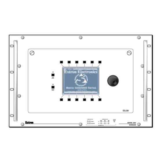
• Adding Video cards to a Matrix 6400 Wideband Switcher- see Page 5-7. • Adding Video cards to a Matrix 3200 Wideband Switcher- see Page 5-9. • Adding BMEs to a Matrix 3200/6400 System - see Page 5-13. Adding a Front Panel Controller to an existing system Adding a Front Panel Controller to an existing system involves replacing the blank Access Panel on any BME (except Sync) with the FPC 1000 panel. -
Page 45: Bme Internal Access
A Ribbon Cable is located behind panel in this area Captive screws MUTE AUDIO MUTE FPC-1000 POWER SUPPLIES COMMUNICATIONS SYSTEM RS232 STATUS PRIMARY MATRIX 6400 REDUNDANT WIDEBAND DIAGNOSTICS Figure 5-2.B Figure 5-2.C Figure 5-2.D Extron • Matrix 3200/6400 Series • User’s Manual... -
Page 46: Installing A Software Update
IC AT IO NS D IA TI C Main Control Card RED + MAIN + RED - MAIN - To Diagnostics LEDs Figure 5-3.A Updating the Software IC on the Main Control Card Extron • Matrix 3200/6400 Series • User’s Manual... -
Page 47: Swapping Rs-232 / Rs-422 Ports
5. Plug in the AC power cord, power ON the BME. MAIN + RED + RS-422 To RS-232/RS-422 RED - Connector RS-232 MAIN - To Diagnostics LEDs Figure 5-4.B Main Control Card - for card location, see Figure 5-3.A. Extron • Matrix 3200/6400 Series • User’s Manual... -
Page 48: Troubleshooting A Matrix 3200/6400 System Problem
Chapter 5 • Upgrades and Troubleshooting Troubleshooting a Matrix 3200/6400 System Problem All Matrix 3200/6400 BME front panels include LEDs at the bottom of the panel which are bracketed and labeled DIAGNOSTICS. These LEDs (Figure 5-6.A) indicate the current status of the BME power supplies, the RS232/BME/MKP Communications RX and TX lines, and the System Status. - Page 49 Power Supply Cable Fuse Primary V- Power Supply R SU DI AG (Redundant V- IC S located above) POWER SUPPLIES COMMUNICATIONS SYSTEM STATUS RS232 PRIMARY REDUNDANT Figure 5-6.A BME exploded view. DIAGNOSTICS Extron • Matrix 3200/6400 Series • User’s Manual...
-
Page 50: Matrix 6400 Wideband Video Switcher Upgrade - Adding Video Circuit-Cards
Fuse Fuse Cable Fuse W ER LI ES IM AR 23 2 IC AT IO NS D IA TI C Figure 5-7.A Extron • Matrix 3200/6400 Series • User’s Manual... - Page 51 64x64, plug 12- input video cards into JC3, JC4, JC7, JC8 and JC9 - JC16, and 4- output cards into JD6 - JD8. P/N 60-250-DH P/N 60-250-HH P/N 60-250-LH P/N 60-250-PH Extron • Matrix 3200/6400 Series • User’s Manual...
-
Page 52: Matrix 3200 Wideband Video Switcher Upgrade - Adding Video Circuit-Cards
Chapter 5 • Upgrades and Troubleshooting Matrix 3200 Wideband Video Switcher Upgrade - Adding Video Circuit-Cards Upgrading a Matrix 3200 Video Switcher which has a matrix size smaller than 32x32 requires adding one or more video cards. Both Input and Output Video cards may be required as shown in Figure 5-9.A below. - Page 53 Determining Matrix 3200 Wideband Video BME Circuit Card Population The drawing above shows the layout of the input and output video circuit card connectors on the inside of the Matrix 3200 Wideband Switcher rear panel. The chart below shows the REQUIRED circuit card population for every possible matrix configuration.
-
Page 54: Adding Bme(S) To A Matrix 3200/6400 System
Chapter 5 • Upgrades and Troubleshooting Adding BME(s) to a Matrix 3200/6400 System Adding BME(s) to an existing Matrix 3200/6400 System involves doing most of the same steps as an initial installation. Extron recommends that the following steps be done in the order listed to add BME(s). -
Page 55: Software Procedure - Before And After A Hardware Upgrade
Chapter 5 • Upgrades and Troubleshooting Software Procedure – Before and After a Hardware Upgrade Prior to upgrading a Matrix 3200/6400 Wideband Video Switcher System, read the “Upgrade System – Software Procedure” below. The suggested procedure can save you a lot of time reconfiguring a system that is going to have a hardware upgrade installed. - Page 56 Notes...
- Page 57 Matrix 3200 & 6400 Wideband Video/Sync Switchers Appendix A Reference Information Switcher Part Numbers Related Part Numbers BNC Cables Glossary of Terms Work-sheets...
-
Page 58: Matrix 3200/6400 Series Part Numbers
Matrix 6400 Wideband, but with different tables as shown on Page A-2. The io characters for the Matrix 3200 Sync part number are DD as it is only available in one matrix size, 32x32. The io characters for the Matrix 6400 Sync part numbers are PH as it is also available in only one matrix size, 64x64. - Page 59 Appendix A • Reference Information Matrix 3200/6400 Series Part Numbers (continued from previous page) Extron Part Part # Matrix 6400 Wideband Switcher 60-250-iofr Two io (Inputs/Outputs) characters = table matrix size coordinate points. f = Front Panel Controller (FPC), 0 = No, 1 = Yes...
- Page 60 Appendix A • Reference Information Matrix 3200/6400 Series Part Numbers (continued from previous page) Extron Part Part # FPC 1000 (Matrix 6400 Series) 60-276-01 FPC 1000 (Matrix 3200 Series) 60-276-02 MCP 1000M 60-298-01 MCP 1000S 60-298-02 MKP 1000 (Gray) 60-239-01...
-
Page 61: Binary/Hex/Decimal Conversion Table
86/06h 87/07h 88/08h 89/09h 10 8A/0Ah 11 8B/0Bh 12 8C/0Ch 13 8D/0Dh 14 8E/0Eh 15 8F/0Fh 16 90/10h etc. 32 A0/20h etc. 64 C0/40h etc. 99 E3/63h 100 E4/64h etc. 127 FF/7F Extron • Matrix 3200/6400 Series • User’s Manual... -
Page 62: Glossary Of Terms
Chrominance Signal – Part of a television signal containing the color information. Abbreviated by “C”. Coaxial Cable – A two-conductor wire in which one conductor completely wraps the cable. Extron • Matrix 3200/6400 Series • User’s Manual... - Page 63 Opposite of Attenuation. Genlock – A method of synchronizing video equipment by using a common, external “Genlock” signal. Hertz – Hz – A measure of frequency in cycles per second. Extron • Matrix 3200/6400 Series • User’s Manual...
- Page 64 Nonvolatile memory – Memory that retains data when power is turned off. NTSC – National Television Standards Committee – Television standard for North America and certain countries in South America. 525 lines/60 Hz (60 Hz Refresh). Extron • Matrix 3200/6400 Series • User’s Manual...
- Page 65 37-pin, D-type connectors, it is often used with others, including 25-pin D-types. It is also used as the serial port standard for Macintosh computers. This signal governs the asynchronous transmission of computer data at speeds of up to 920,000 bits per second. Extron • Matrix 3200/6400 Series • User’s Manual...
- Page 66 Referred to as a “virtual conference room”. Virtual conference room — See videoconferencing. Virtual map — Used with Extron’s virtual matrix switchers (Matrix 3200/6400), a virtual map is made up of tables stored in memory that relate physical connectors (as on the back panel) to logical connections (as seen by the user).
- Page 67 Appendix A • Reference Information Matrix 6400 Wideband Video Switcher Virtualization Work-sheet A-10 Extron • Matrix 3200/6400 Series • User’s Manual...
- Page 68 Appendix A • Reference Information Matrix 3200 Wideband Video Switcher Virtualization Work-sheet A-11 Extron • Matrix 3200/6400 Series • User’s Manual...
-
Page 69: Warranty
Extron’s Warranty Extron Electronics warrants this product against defects in materials and workmanship for a period of two years from the date of purchase. In the event of malfunction during the warranty period... - Page 70 Beeldschermweg 6C, 3821 AH Amersfoort 135 Joo Seng Rd. #04-01, PM Industrial Bldg. ExtronWEB ™ : www.extron.com 800.633.9876 714.491.1500 FAX 714.491.1517 +31.33.453.4040 FAX +31.33.453.4050 +65.383.4400 FAX +65.383.4664 ExtronFAX ™ : 714.491.0192 The Netherlands Singapore 368363 24-hour access—worldwide! © 2001 Extron Electronics. All rights reserved.
Need help?
Do you have a question about the Matrix 3200 Series and is the answer not in the manual?
Questions and answers