Table of Contents
Advertisement
Quick Links
Advertisement
Table of Contents

Related Manuals for Siemens SENTRON ATC6500


Summary of Contents for Siemens SENTRON ATC6500
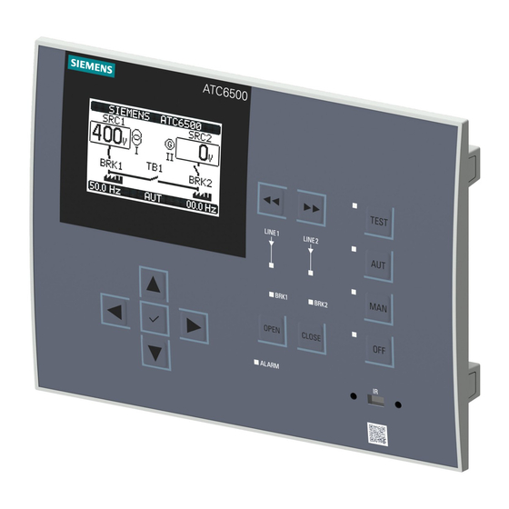
- Page 1 3KC ATC6500 transfer control device...
- Page 3 Introduction General information Applications SENTRON Product description Transfer switching equipment and load transfer switches Functions 3KC ATC6500 transfer control device Installation Manual Connection Operation Parameterization MODBUS communication Accessories Transfer Technical specifications Dimension drawings ESD Guidelines List of abbreviations 05/2019 L1V30538268002A-01...
- Page 4 Note the following: WARNING Siemens products may only be used for the applications described in the catalog and in the relevant technical documentation. If products and components from other manufacturers are used, these must be recommended or approved by Siemens. Proper transport, storage, installation, assembly, commissioning, operation and maintenance are required to ensure that the products operate safely and without any problems.
-
Page 5: Table Of Contents
Security information ........................ 13 1.3.2 Open Source Software......................14 General information ..........................15 Features of the ATC6500 transfer control device ..............15 Compatible Siemens SENTRON switching devices ............... 17 Applications ............................19 Transfer control ........................19 3.1.1 Network/network application ....................19 3.1.2... - Page 6 Table of contents Description of the main menu ....................36 4.5.1 Description of the symbols ..................... 37 Navigation through the main menu ..................38 Display pages of the ATC6500 ....................38 4.7.1 Description of the display pages .................... 38 4.7.1.1 Voltage L-L ..........................
- Page 7 7.3.3 Technical specifications of the Siemens SENTRON switching devices (IEC only) ....105 7.3.4 Typical operating times of the Siemens SENTRON switching devices (IEC only) ....107 Connection of 3VA molded case circuit breakers ..............109 7.4.1 Connection of 3VA molded case circuit breakers with MO (IEC, UL), 3VA with SEO (IEC only) ..........................
- Page 8 Table of contents Connection of 3WL air circuit breakers, FS I - III ..............127 7.6.1 Transfer between two 3WL FS I-III air circuit breakers, with electrical interlock ....127 7.6.2 Transfer between three 3WL air circuit breakers FS I-III, with electrical interlock ....129 7.6.3 Transfer between three 3WL air circuit breakers FSI-III, without electrical interlock ...
- Page 9 Table of contents 9.4.10 P10 - Communications......................177 9.4.11 P11 - Automatic Test ......................178 9.4.12 P12 - Digital Inputs ........................ 179 9.4.13 P13 - Digital Outputs ......................180 9.4.14 P14 - Miscellaneous ......................180 9.4.15 P15 - User limit thresholds LIMx ................... 181 9.4.16 P16 - Counter CNTx ......................
- Page 10 Table of contents Transfer ............................... 227 12.1 Transfer types ........................227 12.1.1 Open transition ........................227 12.1.2 IN-PHASE transition ......................228 12.2 Transfer sequence ....................... 229 12.2.1 Transfer sequence for application A: 2S - 0T ..............229 12.2.2 Transfer sequence for application B: 2S - 1T - PL............... 230 12.2.3 Transfer sequence for application C: 2S - 1T - SI ...............
-
Page 11: Introduction
Introduction About this documentation Purpose of this manual The information contained in this manual enables you to install, operate and use the 3KC ATC6500 transfer control device. The manual contains information on: ● Product specifications ● Installation ● Operation ● Configuration ●... -
Page 12: Product-Specific Information
Introduction 1.2 Product-specific information Product-specific information 1.2.1 Certification Certification 3KC ATC6500 transfer control device Manual, 05/2019, L1V30538268002A-01... -
Page 13: Reference Documents
Reference documents Further documents and information You can find additional information in the following documents: Title Article number Link Siemens switching devices homepage Siemens switching devices homepage (http://www.siemens.com/switching-devices) Operating instructions 3KC ATC6300 3ZW1012-0KC00-1AA0 3KC ATC6300 transfer control device transfer control device (https://support.industry.siemens.com/cs/ww/en/view/1... -
Page 14: Advanced Training Courses
1.2.3 Advanced training courses Find out about training courses on offer on the following link. Training for Industry (https://www.siemens.com/sitrain-lowvoltage) This is where you can choose from ● Web-based training courses (online, informative, free) ● Classroom training courses (course attendance, comprehensive, subject to fee) You also have the possibility of compiling your own training portfolio via Learning paths. -
Page 15: Safety Instructions
Siemens’ products and solutions undergo continuous development to make them more secure. Siemens strongly recommends that product updates are applied as soon as they are available and that the latest product versions are used. Use of product versions that are no longer supported, and failure to apply the latest updates may increase customer's exposure to cyber threats. -
Page 16: Open Source Software
Product or any OSS components contained in it if they are modified or used in any manner not specified by SIEMENS. The license conditions listed below may contain disclaimers that apply between you and the respective licensor. -
Page 17: General Information
General information Features of the ATC6500 transfer control device The 3KC ATC6500 transfer control device, in combination with Siemens motor-driven circuit breakers (ACB, MCCB), enables a transfer between a main and an alternative power source. The stability of the power supply is analyzed by means of voltage taps upstream of the switching devices. - Page 18 ● Deviation of the phase displacement angle cos phi of the two sources Area of application The ATC6500 transfer control device can be used in conjunction with Siemens switching devices in areas in which a continuous power supply needs to be ensured.
-
Page 19: Compatible Siemens Sentron Switching Devices
General information 2.2 Compatible Siemens SENTRON switching devices Compatible Siemens SENTRON switching devices The ATC6500 permits the transfer between two supply sources using the following Siemens products. Note Transfer between circuit breakers A motor operator must be implemented to switch between circuit breakers. - Page 20 General information 2.2 Compatible Siemens SENTRON switching devices 3KC ATC6500 transfer control device Manual, 05/2019, L1V30538268002A-01...
-
Page 21: Applications
The ATC6500 functions as transfer switching equipment in connection with two Siemens 3VA molded case circuit breakers with motor operators, and in connection with two 3WL or 3WT air circuit breakers. -
Page 22: Network/Generator Application
Applications 3.1 Transfer control 3.1.2 Network/generator application For the network/generator application the load is normally connected to the main source (Source 1). Following a deviation in the voltage or frequency, and after the defined delay time, a start signal is sent to the generator (Source 2). If the generator supplies the desired voltage, the load is transferred to the secondary source (generator) until the main source supplies the desired supply quality. -
Page 23: Application A: 2S - 0T
Applications 3.1 Transfer control 3.1.4.1 Application A: 2S – 0T SRC1 (kVA) = SRC2 (kVA) In this application two motor-driven circuit breakers with one outgoing load are used. The ATC6500 switches to one of the two sources, depending on the setting. The states can be obtained from the table: Source 1 (SRC1) Source 2 (SRC2) -
Page 24: Application B: 2S - 1T - Pl
Applications 3.1 Transfer control 3.1.4.2 Application B: 2S - 1T - PL SRC1 (kVA) > SRC2 (kVA) In this application three motor-driven circuit breakers are used. A distinction is made between prioritized load and non-prioritized load (NPL). On failure of the prioritized sources (in this case, Source 1), only the prioritized load is supplied by the secondary source (in this case, Source 2). -
Page 25: Application C: 2S - 1T - Si
Applications 3.1 Transfer control 3.1.4.3 Application C: 2S – 1T – SI SRC1 (kVA) = SRC2 (kVA) In this application three motor-driven circuit breakers are used. A distinction is made between prioritized load and non-prioritized load (NPL). In this case, both loads are supplied by one source each in normal circumstances (both sources available). -
Page 26: Application D: 2S - 1T - Ai
Applications 3.1 Transfer control 3.1.4.4 Application D: 2S - 1T - AI SRC1 (kVA) > SRC2 (kVA) In this application three motor-driven circuit breakers are used. A distinction is made between prioritized load and non-prioritized load (NPL). In this application, both loads are supplied by one source each in normal circumstances (both sources available). -
Page 27: Application O: 2S - Npl
Applications 3.1 Transfer control 3.1.4.5 Application O: 2S - NPL SRC1 (kVA) > SRC2 (kVA) In this application three motor-driven circuit breakers are used. A distinction is made between prioritized load and non-prioritized load (NPL). In this application, on failure of the prioritized sources (in this case, Source 1), only the prioritized load is supplied by the secondary source (in this case, Source 2). -
Page 28: Controlling The Switching Devices
Applications 3.2 Controlling the switching devices Controlling the switching devices The ATC6500 can control various devices for automatic transfer switching. How the control of the switching devices can be implemented is shown below. ● Depending on the type of transfer device used, the appropriate circuit diagram shall be used (see chapter Connection (Page 83)), as well as the programmable inputs/outputs on the ATC6500 (see chapter Inputs and outputs of the ATC6500 (Page 144)). -
Page 29: Controlling Motor-Driven Circuit Breakers
Applications 3.2 Controlling the switching devices 3.2.1 Controlling motor-driven circuit breakers The control of motor-driven circuit breakers requires four outputs (open and close commands for Source 1 and Source 2) and two inputs for circuit breaker status feedback for the application with two circuit breakers. -
Page 30: Controlling Contactors
Applications 3.3 Voltage measurement 3.2.3 Controlling contactors If contactors are used, two outputs (Close 1 and Close 2) and two status inputs are required. If an additional contactor is used as a tie breaker, an additional output (close tie breaker) and a status input are required. -
Page 31: P02 General
Applications 3.3 Voltage measurement 3.3.1 P02 General ● The general system settings can be adjusted in Menu P02. In the menu the system configuration (application) is set (see chapter Load management with the ATC6500 (Page 20)). ● The nominal voltage and frequency are also set in P02. These are used as a reference for setting the percentage thresholds. -
Page 32: P09 Source Line Chk
Applications 3.3 Voltage measurement 3.3.4 P09 Source Line CHK In this menu the limit thresholds for the sources are defined. ● Each measurement can be assigned a specific delay time. Measured anomalies (beyond the threshold values) must be present for longer than the set delay times, before it can be concluded that there is a line fault. - Page 33 Applications 3.3 Voltage measurement The table below lists the measurements of the two sources. Some thresholds can also be deactivated for triggering the transfer. Measurement Description Can be deactivated Minimum voltage One or more phases too low Maximum voltage One or more phases too high Voltage deviation of the two sources The tolerated delta between the voltage Yes, if P08.14 is disabled...
- Page 34 Applications 3.3 Voltage measurement 3KC ATC6500 transfer control device Manual, 05/2019, L1V30538268002A-01...
-
Page 35: Product Description
Product description User interface 3KC ATC6500 transfer control device Manual, 05/2019, L1V30538268002A-01... -
Page 36: Status Leds
Product description 4.1 Status LEDs Status LEDs The LEDs on the operator panel indicate the status of the device and/or the controlled switching devices. The meaning of the various LEDs is shown in the following table: LED ON LED OFF LED FLASHING TEST Shows a steady orange light if... -
Page 37: Keys
Product description 4.2 Keys See also Parameters (Page 160) Keys Function << Using this key in the manual mode, it is possible to toggle between the switching devices >> Using this key in the manual mode, it is possible to toggle between the switching devices TEST Pressing the TEST key for more than 0.5 seconds selects the TEST mode. -
Page 38: Menu Navigation
Product description 4.4 Menu navigation Menu navigation The following section describes the front-mounted LCD. This display enables the device to be parameterized (see chapter Parameterization (Page 155)). In addition, measured values relating to voltage and frequency can be read from it. Description of the main menu Procedure for opening the main menu ●... -
Page 39: Description Of The Symbols
Product description 4.5 Description of the main menu 4.5.1 Description of the symbols The symbols are used as shortcuts, with which the display pages of the measurements can be retrieved faster. They enable a jump to be made directly to the selected group of messages. From there, it is possible to scroll forward or back as usual. -
Page 40: Navigation Through The Main Menu
Product description 4.6 Navigation through the main menu Navigation through the main menu Press ► and ◄ or ▲ and ▼ to scroll through the main menu functions in a clockwise / counter- clockwise direction. The selected symbol is highlighted, and the description of the function is shown in the center of the display. -
Page 41: Voltage L-L
4.7 Display pages of the ATC6500 network applications change according to the application that is set. The application is defined via the parameter P02.01. The designation in the SIEMENS ATC6500 field can be freely set by the user. See also Parameters (Page 160) 4.7.1.1... -
Page 42: Threshold Limits
Product description 4.7 Display pages of the ATC6500 The submenu L-N Voltage shows the voltage between the phase and the neutral conductor. The menu shows ● the voltages currently being measured ● the frequency of both sources currently being measured ●... -
Page 43: Alarms Status
Product description 4.7 Display pages of the ATC6500 4.7.1.4 Alarms status The Alarms Status submenu lists all possible alarms of the ATC6500. If an alarm is active the corresponding alarm has a black background. 4.7.1.5 Statistics ① Source 2 ② Counter of the switching operations to Source 2 in the automatic mode ③... -
Page 44: Battery Status
Product description 4.7 Display pages of the ATC6500 4.7.1.6 Battery Status ① Measured maximum voltage of the DC supply ② Upper limit of the DC supply ③ Lower limit of the DC supply ④ Current voltage of the DC supply ⑤... -
Page 45: Inputs/Outputs
Product description 4.7 Display pages of the ATC6500 4.7.1.8 Inputs/outputs In the Input/Output Status submenu all digital inputs and outputs can be viewed. If an input/output is active, the corresponding input or output is shown with a black background. In addition to the permanently integrated inputs and outputs (8 inputs and 7 outputs) of the ATC6500, the possible inputs and outputs of the expansion modules are also shown here. -
Page 46: Date/Time
From this page, it is also possible to adjust the date and / or the time (see chapter Setting the real-time clock (Page 51)). 4.7.1.12 Information page 1 The SIEMENS ATC6500 field can be freely designated by means of Menu P01, Parameter P01.10 (see chapter P01 - Settings (Page 161)). 3KC ATC6500 transfer control device Manual, 05/2019, L1V30538268002A-01... -
Page 47: Event Log
Product description 4.7 Display pages of the ATC6500 Information page 2 Information page 3 4.7.1.13 Event log The event log allows you to view the last 250 events. In addition to the code a message is shown in plain text. 3KC ATC6500 transfer control device Manual, 05/2019, L1V30538268002A-01... -
Page 48: Counter Cntx
Product description 4.7 Display pages of the ATC6500 4.7.1.14 Counter CNTx This page is only visible if the Counters function has been activated. In the Counters menu the status of active counters can be viewed. It shows how often the defined status has occurred. -
Page 49: Automatic Test
Product description 4.7 Display pages of the ATC6500 4.7.1.16 Automatic test In the Automatic Test menu you can view all settings regarding the automatic test function. For more information, refer to chapter Automatic Test (Page 67). 4.7.1.17 Setup menu This menu is only visible if the symbol was selected on the main menu. -
Page 50: Password
Product description 4.7 Display pages of the ATC6500 4.7.1.18 Password The Password menu is only visible if the symbol was selected on the main menu. This menu is used for entering the password. You can find more information in chapter Password protection (Page 52). -
Page 51: Synchronoscope
Product description 4.7 Display pages of the ATC6500 4.7.1.20 Synchronoscope This window is only visible if IN-PHASE transition is selected. ① DELTA of voltages (L1-L2-L3) of both sources ② Real-time values of voltages (L1-L2-L3) of Source 2 ③ Real-time value of frequency of Source 2 ④... -
Page 52: Delta Voltages
Product description 4.7 Display pages of the ATC6500 4.7.1.22 Delta voltages This window is only visible if IN-PHASE transition is selected. ① DELTA of voltages of both sources ② Currently selected mode ③ Frequency, Source 1 4.7.2 Scrolling through the display pages You can scroll through any display pages on the ATC6500 using the ▲... -
Page 53: Functions
Functions The following chapter contains information on: ● Basic functions ● Advanced functions Basic functions 5.1.1 Setting the real-time clock The virtual calendar clock of the ATC6500 must be set when the device is first commissioned. You can select whether the clock is to be reset after each device restart. This can be set using parameter P01.02 (refer to chapter P01 Settings (Page 161)). -
Page 54: Password Protection
Functions 5.1 Basic functions 5.1.2 Password protection Access to the ATC6500 can be denied by means of a password. Both the physical access to the device and the access via MODBUS can be protected with a password. Note Default setting On new devices the factory setting is as follows: one password is activated for the user level, one for the advanced level, and one remote password for remote access. -
Page 55: Password Protection Against Remote Access (Remote Password)
Functions 5.1 Basic functions The remaining parameters / commands are grayed out. If you attempt to open a menu without a password, the following message is displayed: Advanced password With the advanced password, all parameters can be changed, and all commands executed. 5.1.2.2 Password protection against remote access (remote password) To restrict remote access to the device via MODBUS, a 4-digit numerical code can also be... - Page 56 Functions 5.1 Basic functions After you have clicked on the symbol, the following window appears: Procedure for password entry 1. Change the value of the selected digit with the ▲ and ▼ keys. 2. Move from digit to digit using the ◄ and ► keys. 3.
-
Page 57: Keypad Lock
Functions 5.1 Basic functions 5.1.3 Keypad lock In addition to password protection, the operator panel of the ATC6500 can also be disabled. The purpose of this is to prevent changes being made to the ATC6500 by touching the keys. The keypad lock can be implemented in two different ways: ●... -
Page 58: Expandability By Modules
Functions 5.1 Basic functions 5.1.4 Expandability by modules On the back of the ATC6500 there are three slots for expansion modules. These can be used to extend the functionality of the device. For additional information on installing the expansion modules, please refer to the chapter Inserting an expansion module (Page 58). ①... -
Page 59: Enabling Additional Resources
Functions 5.1 Basic functions 5.1.4.1 Enabling additional resources The expansion modules provide additional resources that can be used via the corresponding Setup menus. Note Availability during physical absence of modules The Setup menus for the expansions are also available if the modules are not physically present, i.e. -
Page 60: Inserting An Expansion Module
Functions 5.1 Basic functions 5.1.4.2 Inserting an expansion module In order to insert an expansion module, proceed as follows: WARNING Hazardous voltage. Will cause death or serious injury. Turn off and lock out all power supplying this equipment before working on the device. Replace all covers before power supplying this device is turned on. -
Page 61: Behavior Of The Atc6500 After Inserting A Module
Functions 5.1 Basic functions You will find further information on the expansion modules in the operating instructions ● ATC6 DI/DO expansion modules ● ATC6 Ethernet expansion modules 5.1.4.3 Behavior of the ATC6500 after inserting a module As soon as the power supply is connected to the ATC6500, it automatically detects a new expansion module. -
Page 62: Communication Comx
Functions 5.1 Basic functions The current system configuration is displayed on the corresponding display page (Expansion Modules), stating the number, type and status of the connected modules: ● The I/O numbering is shown under each module. ● The status (activated / deactivated) of the I/O and of the communication channels is indicated by the message displayed in negative. -
Page 63: Alarms
Functions 5.1 Basic functions Note Addressing on removal of a module If there are two additional modules for communication on the device and the module in the COM2 slot is subsequently removed, then the addressing of the remaining module changes from COM3 to COM2. -
Page 64: Features Of The Alarms
Functions 5.1 Basic functions 5.1.6.1 Features of the alarms Various features can be assigned to each alarm, including the user alarms (UAx see chapter User alarms (Page 67)). ● Alarms enabled (Enable) General enabling of the alarm. If an alarm has not been enabled, the procedure is as if the alarm did not exist. -
Page 65: Alarm Description
Functions 5.1 Basic functions 5.1.6.2 Alarm description The predefined alarms have the following features: Code Description Cause of alarm Voltage of the DC supply too low The voltage of the DC supply is below the lower threshold limit for longer than the set time. - Page 66 Functions 5.1 Basic functions Code Description Cause of alarm Auxiliary voltage failure The device that manages the draw of auxiliary voltage supply from one of the available lines signals a failure or improper operation. Timeout tie breaker (TB) The tie breaker has not performed any opening or closing operation within the set maximum period.
-
Page 67: Alarm Table
Functions 5.1 Basic functions 5.1.6.3 Alarm table The features of the alarms can be modified using Menu P22. This can be selected from the Setup menu. The alarms have the following features (for a definition of the features, please refer to chapter Features of the alarms (Page 62)). Code Description Ena- Only... - Page 68 Functions 5.1 Basic functions Code Description Ena- Only Global Global Lock Lock Siren Inhi- bled tained alarm A alarm B BRK 1 BRK 2 bition Tie breaker TB withdrawn User alarm UA1…8 …8 Note Inhibition function The "Inhibition" function is not activated in the factory settings but can be selected or deselected by the user.
-
Page 69: User Alarms Uax
Functions 5.1 Basic functions 5.1.6.4 User alarms UAx The user can define up to 8 programmable alarms (UA1…UA8). For each alarm, the following can be specified: ● The source, i.e. the condition that triggers the alarm. The following functions can be used as alarm sources: –... -
Page 70: Enabling The Automatic Test
Functions 5.1 Basic functions Note: In an application with two generators, only one is started. The other generator is started in the next cycle. When the automatic test starts, the unit is tested for the time defined in P11.14. Before the generator starts, the message "T.AUT"... -
Page 71: Simulation Of Priority Source Failure (Test Mode)
Functions 5.1 Basic functions 5.1.8 Simulation of priority source failure (test mode) In addition to the automatic test, a failure of the priority source can be simulated. This simulation can be performed in several ways: ● By pressing the TEST key for 5 seconds or more (see TEST operating mode) until the display of the simulation duration is visible ●... -
Page 72: Commands Menu
Functions 5.1 Basic functions 5.1.9 Commands menu By means of the Commands menu, any processes, such as the resetting of measurements, counters, alarms etc., can be executed. 5.1.9.1 Executing a command In order to reach the command menu, it is necessary to click on the corresponding symbol in the main menu (OFF mode must be active): Note Password protection... - Page 73 Functions 5.1 Basic functions The following message is displayed: By pressing the ✓ key again, the command is executed. In order to cancel the execution of a selected command, press OFF. The following message is displayed: Press OFF in order to exit the command menu. 3KC ATC6500 transfer control device Manual, 05/2019, L1V30538268002A-01...
-
Page 74: Table Of Commands
Functions 5.1 Basic functions 5.1.9.2 Table of commands The following table lists the available commands: Code Command Designation on the Required Description password Reset maintenance hours RES. MAIN. 1 HRS Advanced Reset maintenance interval hours 1 Source 1 Reset maintenance hours RES. -
Page 75: Event Log
Functions 5.1 Basic functions Code Command Designation on the Required Description password Reset alarms A03 - A04 RESET A03/04 Advanced Restores the opening or closing command of the switching devices after generating the alarms A03 - A04 Simulates priority source fail- FAIL.SIMULATION Advanced The device switches to test mode and simu- lates failure of the priority source for two... -
Page 76: Advanced Functions
Functions 5.2 Advanced functions Advanced functions 5.2.1 Remote variables REMx The ATC6500 can control a maximum of 8 remote variables. A remote variable is a variable used internally that can be switched on and off by the user. It is switched on and off via MODBUS, see chapter Commands (use with MODBUS function 06) (Page 199). -
Page 77: User Limit Limx
Functions 5.2 Advanced functions 5.2.2 User limit LIMx The ATC6500 provides the option of specifying 16 user limits. The LIMx limits are internal variables whose status is dependent on whether one of the measurements performed by the system has exceeded the limit specified by the user (example: Voltage between L1-L2 higher than 400 V). - Page 78 Functions 5.2 Advanced functions Designation on Description the ATC6500 Year The year serves as a source for the limit threshold. Month The current month serves as a source for the limit threshold. The current day serves as a source for the limit threshold. Hour The current hour serves as a source for the limit threshold.
-
Page 79: Timer Timx
Functions 5.2 Advanced functions Setting: LIM1 Reference measurement: V L1-N Source: Source 1 Channel number: 1 Function: Min + Max Upper limit: 250 V Multiplier: 1 Delay: 0.0 s Lower limit: 220 V Multiplier: 1 Delay: 0.0 s You can find a more detailed description of the parameters in chapter P15 - Limit Thresholds LIMx (Page 181). -
Page 80: Counter Cntx
Functions 5.2 Advanced functions Example: If user limit threshold LIM1 is exceeded, TIMER TIM1 should activate output OUT7 after 10s. P17.1.01: LIMx P17.1.02: 1 P17.1.03: 10s P13.07.01: TIMx P13.07.02: 1 5.2.4 Counter CNTx In addition to the counters that are set automatically and which can be viewed under the menu option Statistics (see chapter Description of the display pages (Page 38)), counters can also be defined by the user. -
Page 81: Installation
● Dimensions for the door cutout ● Installation of the ATC6500 Additional information can be found in the Operating instructions for 3KC ATC6500 transfer control device (https://support.industry.siemens.com/cs/ww/en/view/109764908). Dimensions for the door cutout The ATC6500 is intended for door mounting. When correctly installed and with simultaneous use of the IP protective seal 3KC9000- 8TL68, IP65 protection is achieved at the front. -
Page 82: Installation Of The Atc6500
Installation 6.2 Installation of the ATC6500 Installation of the ATC6500 The ATC6500 is attached to the door using the clips included in the scope of delivery. Installation procedure Note Sequence of operations during installation If you are using the IP protective seal 3KC9000-8TL68, fit this before installing the ATC6500. 3KC ATC6500 transfer control device Manual, 05/2019, L1V30538268002A-01... - Page 83 Installation 6.2 Installation of the ATC6500 1. Fit the IP protective seal 3KC9000-8TL68 to the ATC6500. 2. Mount the ATC6500 in the door cutout. 3. Attach the two clips on the side of the ATC6500. 4. Press the clips toward the back to engage them. 5.
- Page 84 Installation 6.2 Installation of the ATC6500 3KC ATC6500 transfer control device Manual, 05/2019, L1V30538268002A-01...
-
Page 85: Connection
● Connection of the power supply ● General connection drawings ● Connection of Siemens switching devices Connection of the power supply for the ATC6500 The ATC6500 has inputs for an auxiliary power supply and inputs for a supply by means of a separate DC power source. - Page 86 Connection 7.1 Connection of the power supply for the ATC6500 Technical specification of the ATC6500 power supply Designation Feature Recommended cable cross-section DC power supply 12 - 48 V DC (7.5 - 57.6 V DC) 0.2 - 2.5 mm (24 - 12 AWG) According to UL508: 0.75 - 2.5 mm (18 - 12 AWG)
-
Page 87: Use Of A Dc Source / Battery
Connection 7.1 Connection of the power supply for the ATC6500 7.1.1 Use of a DC source / battery Voltage tap from the priority source and additional battery The schematic diagram below shows how taps from the priority source and an additional DC source can be used to implement the continuous power supply to the ATC6500: Using taps, the ATC is supplied by the priority source in normal circumstances (Source 1 available) via the terminals 53, 54. - Page 88 Connection 7.1 Connection of the power supply for the ATC6500 Use of the DC source without additional voltage taps The schematic diagram below shows how a DC source can be used to implement the continuous power supply to the ATC6500: When using a DC source, the ATC6500 does not switch off during a transfer.
-
Page 89: Power Supply Using A Dual Power Supply
ATC6500 must be observed (see chapter Connecting the power supply of the ATC6500 (Page 83)) as well as the technical specifications of the additional dual network connection. Additional information is available in the Operating Instructions for 3KC9625-1 (https://support.industry.siemens.com/cs/ww/en/view/109738022). See also Technical specifications (Page 237) 3KC ATC6500 transfer control device... -
Page 90: Power Supply By Means Of Ups
Connection 7.1 Connection of the power supply for the ATC6500 7.1.3 Power supply by means of UPS The ATC6500 can also be supplied by means of an uninterruptible power supply (UPS). The UPS buffers the supply voltage during a transfer to a secondary source. This ensures that the ATC6500 does not fail during a transfer. -
Page 91: Power Supply By Means Of Contactors
Connection 7.1 Connection of the power supply for the ATC6500 7.1.4 Power supply by means of contactors It is also possible to switch between two auxiliary power supplies using two mechanically and electrically interlocked contactors. Code Description K1 / K2 Contactors (switching power supply between priority source and secondary source) Mechanical interlock... -
Page 92: General Connection Drawings
Connection 7.2 General connection drawings General connection drawings 7.2.1 Transfer between 2 sources, with 2 breakers The schematic diagram below shows the setup of a transfer between 2 breakers. For this purpose, the application 2S- 0T must be used (see chapter Application A: 2S – 0T (Page 21)). -
Page 93: Transfer With 2 Circuit Breakers
Connection 7.2 General connection drawings 7.2.2 Transfer with 2 circuit breakers With electrical interlock Code Description BRK1 / BRK2 Breaker 1/2 In the drawing shown above an electrical interlock is achieved by means of the auxiliary switches. A mechanical interlock can be applied in addition. Note Implementation of the power supply More information on implementing the power supply of the ATC6500 via the inputs 53, 54... -
Page 94: Transfer With Remotely Operated Transfer Switching Equipment
Connection 7.2 General connection drawings Terminal Parameter code Settings 43 (INP4) P12.4.01 Function of the input INP4 Source 1 breaker protection (Trip 1) 44 (INP5) P12.5.01 Function of the input INP5 Source 2 breaker protection (Trip 2) 55 (OUT1) P13.1.01 Function of the output OUT1 Open Source 1 breaker 57 (OUT2) P13.2.01 Function of the output OUT2... - Page 95 Connection 7.2 General connection drawings The following basic parameters must be set for the circuit diagram shown: Terminal Parameter code Settings P02.01 System configuration A: 2S-0T P02.22 Management of the tie breaker (TB) P08.01 Type of breaker Changeover pulse or changeover continuous 40 (INP1) P12.1.01 Function of the input INP1 Source 1 breaker closed (feedback 1)
-
Page 96: Transfer With Contactors
Connection 7.2 General connection drawings 7.2.4 Transfer with contactors Code Description BRK1 / BRK2 Breaker 1 / 2 F1 / F2 Source fuse Mechanical interlock Note Implementation of the power supply More information on implementing the power supply of the ATC6500 via the inputs 53, 54 and / or the inputs 26, 27 can be found in chapter Connection of the power supply (Page 83). -
Page 97: Transfer Between 2 Sources, With 3 Switching Devices
Connection 7.2 General connection drawings 7.2.5 Transfer between 2 sources, with 3 switching devices The schematic diagram below shows the setup of a transfer with 3 switching devices. For this purpose, the following applications can be used: ● 2S - 1T - PL ●... - Page 98 Connection 7.2 General connection drawings Interlock only possible in the cases described above 3KC ATC6500 transfer control device Manual, 05/2019, L1V30538268002A-01...
-
Page 99: Transfer With 3 Circuit Breakers
Connection 7.2 General connection drawings 7.2.6 Transfer with 3 circuit breakers With electrical interlock between breaker 1 (BRK1) and breaker 2 (BRK2) Code Description BRK1 / BRK2 Breaker BRK1 / 2 Tie breaker TB / NPL In the drawing shown above an electrical interlock is achieved by means of the auxiliary switch interlock. - Page 100 Connection 7.2 General connection drawings The following basic parameters must be set for the circuit diagram shown: Terminal Parameter code Settings P02.01 System configuration 2S – 1T – PL or 2S – NPL P02.22 Management of the tie breaker (TB) Breaker pulse or breaker continuous P08.01 Type of breaker Breaker pulse or breaker continuous...
- Page 101 Connection 7.2 General connection drawings Without electrical interlock between breaker 1 (BRK1) and breaker 2 (BRK2) Code Description BRK1 / BRK2 Breaker BRK1 / 2 Tie breaker TB / NPL An electrical interlock is not achieved in the drawing shown above. In application 2S-1T-AI, breaker BRK2 can be interlocked with the tie breaker.
- Page 102 Connection 7.2 General connection drawings Terminal Parameter code Settings P02.01 System configuration 2S – 1T – SI or 2S – 1T - AI P02.22 Management of the tie breaker (TB) Breaker pulse or breaker continuous P08.01 Type of breaker Breaker pulse or breaker continuous 40 (INP1) P12.1.01 Function of the input INP1 Source 1 breaker closed (feedback 1)
-
Page 103: Connection Of Siemens Sentron Switching Devices
Connection 7.3 Connection of Siemens SENTRON switching devices Connection of Siemens SENTRON switching devices The connection of the Siemens switching devices is shown below, 7.3.1 Accessories for switching devices The following accessories are required for the Siemens switching devices: Circuit breaker Accessories required 3VA11 (160A) –... -
Page 104: Accessories For Mechanical Interlock
Customers who wish to have a mechanical interlocking in addition to, or instead of the electrical interlocking, can obtain the possible combinations of Siemens breakers from the table below. For detailed information, please refer to the corresponding operating manual for the product. - Page 105 Connection 7.3 Connection of Siemens SENTRON switching devices Mechanical interlocking combinations for 3VA51 – 3VA52, 3VA61 – 3VA64 Note: Bowden cable systems cannot be used. You can find more information on interlocking in the Manual "3VA Molded Case Circuit Breakers" (https://support.industry.siemens.com/cs/ww/en/view/90318775).
- Page 106 Connection 7.3 Connection of Siemens SENTRON switching devices For more information on interlocking, see also: ● Manual for 3WL10 air circuit breakers and 3VA27 molded case circuit breakers (https://support.industry.siemens.com/cs/ww/en/view/109753821) ● SENTRON WL Operating Manual - 3WL1 circuit breakers (IEC) (https://support.industry.siemens.com/cs/de/en/view/8912465)
-
Page 107: Technical Specifications Of The Siemens Sentron Switching Devices (Iec Only)
Connection 7.3 Connection of Siemens SENTRON switching devices 7.3.3 Technical specifications of the Siemens SENTRON switching devices (IEC only) The following table lists the required data of the air circuit breakers and molded case circuit breakers. Note Nevertheless, check the data of the circuit breaker used against the corresponding catalog or using the breaker manual. - Page 108 Connection 7.3 Connection of Siemens SENTRON switching devices Key features of the 3VA27 Unit 3VA27 (1600 A) Product standard IEC 60947-2 Rated operational voltage U AC 50 / 60 Hz [V AC] Rated operational current In at 50 °C ambient temperature 800 ...
-
Page 109: Typical Operating Times Of The Siemens Sentron Switching Devices (Iec Only)
Connection 7.3 Connection of Siemens SENTRON switching devices 7.3.4 Typical operating times of the Siemens SENTRON switching devices (IEC only) The following typical operating times can be achieved with the ATC and Siemens circuit breakers. Note Checking The tables below contain typical operating values. Check the operating times of the respective total installation under real conditions. - Page 110 Connection 7.3 Connection of Siemens SENTRON switching devices Operating times of the 3WT Unit 2 x 3WT FSI Time I-O Time II-O Time I-O-II (for min parameter)* * includes the minimum delay time from Source 1 to Source 2 of 100 ms (see parameter P07.n.02)
-
Page 111: Connection Of 3Va Molded Case Circuit Breakers
Connection 7.4 Connection of 3VA molded case circuit breakers Connection of 3VA molded case circuit breakers 7.4.1 Connection of 3VA molded case circuit breakers with MO (IEC, UL), 3VA with SEO (IEC only) 7.4.1.1 Transfer between two 3VA molded case circuit breakers, with electrical interlock For the application 2S-0T the following diagram applies: You can find more information on the applications in chapter Load management with the ATC6500 (Page 20) - Page 112 For additional functions, expansion modules with inputs/outputs can be attached if necessary (see chapter Expansion modules (Page 209)). You can find more information on the technical specifications of the circuit breaker in the Manual "3VA Molded Case Circuit Breakers" (https://support.industry.siemens.com/cs/ww/en/view/90318775). Terminal Parameter code Settings P02.01 System configuration...
-
Page 113: Transfer Between Three 3Va Molded Case Circuit Breakers, With Electrical Interlock
Connection 7.4 Connection of 3VA molded case circuit breakers 7.4.1.2 Transfer between three 3VA molded case circuit breakers, with electrical interlock The following diagram applies for the applications 2S-1T-PL and 2S-NPL: You can find more information on the applications in chapter Load management with the ATC6500 (Page 20) Code Description... - Page 114 For additional functions, expansion modules with inputs/outputs can be attached if necessary (see chapter Expansion modules (Page 209)). You can find more information on the technical specifications of the circuit breaker in the Manual "3VA Molded Case Circuit Breakers" (https://support.industry.siemens.com/cs/ww/en/view/90318775). Terminal Parameter code Settings P02.01 System configuration...
-
Page 115: Transfer Between Three 3Va Molded Case Circuit Breakers, Without Electrical Interlock
Connection 7.4 Connection of 3VA molded case circuit breakers 7.4.1.3 Transfer between three 3VA molded case circuit breakers, without electrical interlock The following diagram applies for the applications 2S-1T-SI and 2S-1T-AI: You can find more information on the applications in chapter Load management with the ATC6500 (Page 20) Code Description... - Page 116 For additional functions, expansion modules with inputs/outputs can be attached if necessary (see chapter Expansion modules (Page 209)). You can find more information on the technical specifications of the circuit breaker in the Manual "3VA Molded Case Circuit Breakers" (https://support.industry.siemens.com/cs/ww/en/view/90318775). Terminal Parameter code Settings P02.01 System configuration...
-
Page 117: Connection Of 3Va27 Motor-Driven Molded Case Circuit Breakers (Iec Only)
Connection 7.4 Connection of 3VA molded case circuit breakers 7.4.2 Connection of 3VA27 motor-driven molded case circuit breakers (IEC only) 7.4.2.1 Transfer between two 3VA27 molded case circuit breakers, with electrical interlock For the application 2S-0T the following diagram applies: You can find more information on the applications in chapter Load management with the ATC6500 (Page 20) Code... - Page 118 For additional functions, expansion modules with inputs/outputs can be attached if necessary (see chapter Expansion modules (Page 209)). You can find more information on the technical specifications of the circuit breaker in the Manual "3WL10 air circuit breakers and 3VA27 molded case circuit breakers" (https://support.industry.siemens.com/cs/ww/en/view/109753821). Terminal Parameter code Settings P02.01 System configuration...
-
Page 119: Transfer Between Three 3Va27 Molded Case Circuit Breakers, With Electrical Interlock
Connection 7.4 Connection of 3VA molded case circuit breakers 7.4.2.2 Transfer between three 3VA27 molded case circuit breakers, with electrical interlock The following diagram applies for the applications 2S-1T-PL and 2S-NPL: You can find more information on the applications in chapter Load management with the ATC6500 (Page 20) Code Description... - Page 120 For additional functions, expansion modules with inputs/outputs can be attached if necessary (see chapter Expansion modules (Page 209)). You can find more information on the technical specifications of the circuit breaker in the Manual "3WL10 air circuit breakers and 3VA27 molded case circuit breakers" (https://support.industry.siemens.com/cs/ww/en/view/109753821). Terminal Parameter code Settings P02.01 System configuration...
-
Page 121: Transfer Between Three 3Va27 Molded Case Circuit Breakers, Without Electrical Interlock
Connection 7.4 Connection of 3VA molded case circuit breakers 7.4.2.3 Transfer between three 3VA27 molded case circuit breakers, without electrical interlock The following diagram applies for the applications 2S-1T-SI and 2S-1T-AI: You can find more information on the applications in chapter Load management with the ATC6500 (Page 20) Code Description... - Page 122 For additional functions, expansion modules with inputs/outputs can be attached if necessary (see chapter Expansion modules (Page 209)). You can find more information on the technical specifications of the circuit breaker in the Manual "3WL10 air circuit breakers and 3VA27 molded case circuit breakers" (https://support.industry.siemens.com/cs/ww/en/view/109753821). Terminal Parameter code Settings P02.01 System configuration...
-
Page 123: Connection Of The 3Wl Air Circuit Breaker
Connection 7.5 Connection of the 3WL air circuit breaker Connection of the 3WL air circuit breaker 7.5.1 Transfer between two 3WL10 air circuit breakers, with electrical interlock For the application 2S-0T the following diagram applies: You can find more information on the applications in chapter Load management with the ATC6500 (Page 20) Code Description... - Page 124 For additional functions, expansion modules with inputs/outputs can be attached if necessary (see chapter Expansion modules (Page 209)). You can find more information on the technical specifications of the circuit breaker in the Manual "3WL10 air circuit breakers and 3VA27 molded case circuit breakers" (https://support.industry.siemens.com/cs/ww/en/view/109753821). Terminal Parameter code Settings P02.01 System configuration...
-
Page 125: Transfer Between Three 3Wl10 Air Circuit Breakers, With Electrical Interlock
Connection 7.5 Connection of the 3WL air circuit breaker 7.5.2 Transfer between three 3WL10 air circuit breakers, with electrical interlock The following diagram applies for the applications 2S-1T-PL and 2S-NPL: You can find more information on the applications in chapter Load management with the ATC6500 (Page 20) Code Description... - Page 126 For additional functions, expansion modules with inputs/outputs can be attached if necessary (see chapter Expansion modules (Page 209)). You can find more information on the technical specifications of the circuit breaker in the Manual "3WL10 air circuit breakers and 3VA27 molded case circuit breakers" (https://support.industry.siemens.com/cs/ww/en/view/90318775). Terminal Parameter code Settings P02.01 System configuration...
-
Page 127: Transfer Between Three 3Wl10 Air Circuit Breakers, Without Electrical Interlock
Connection 7.5 Connection of the 3WL air circuit breaker 7.5.3 Transfer between three 3WL10 air circuit breakers, without electrical interlock For the application 2S-1T-SI and 2S – 1T - AI the following diagram applies: You can find more information on the applications in chapter Load management with the ATC6500 (Page 20) Code Description... - Page 128 The two breakers of the infeed sources are not interlocked in the circuit diagram shown above. A mechanical interlock cannot be applied either. You can find more information on the technical specifications of the circuit breaker in the Manual "3WL10 air circuit breakers and 3VA27 molded case circuit breakers" (https://support.industry.siemens.com/cs/ww/en/view/90318775). Terminal Parameter code Settings P02.01 System configuration...
-
Page 129: Connection Of 3Wl Air Circuit Breakers, Fs I - Iii
Connection 7.6 Connection of 3WL air circuit breakers, FS I - III Connection of 3WL air circuit breakers, FS I - III 7.6.1 Transfer between two 3WL FS I-III air circuit breakers, with electrical interlock For the application 2S-0T the following diagram applies: You can find more information on the applications in chapter Load management with the ATC6500 (Page 20) Code... - Page 130 For additional functions, expansion modules with inputs/outputs can be attached if necessary (see chapter Expansion modules (Page 209)). You can find more information on the technical specifications of the circuit breaker in the Operating Instructions of the 3WL air circuit breaker (https://support.industry.siemens.com/cs/ww/en/view/8912465). Terminal Parameter code Settings P02.01 System configuration...
-
Page 131: Transfer Between Three 3Wl Air Circuit Breakers Fs I-Iii, With Electrical Interlock
Connection 7.6 Connection of 3WL air circuit breakers, FS I - III 7.6.2 Transfer between three 3WL air circuit breakers FS I-III, with electrical interlock The following diagram applies for the applications 2S-1T-PL and 2S-NPL: You can find more information on the applications in chapter Load management with the ATC6500 (Page 20) Code Description... - Page 132 The tie breaker is not interlocked. An additional mechanical interlock can be applied for the two breakers BRK1, BRK2. You can find more information on the technical specifications of the circuit breaker in the Operating Instructions of the 3WL air circuit breaker (https://support.industry.siemens.com/cs/ww/en/view/8912465). Terminal Parameter code Settings P02.01 System configuration...
-
Page 133: Transfer Between Three 3Wl Air Circuit Breakers Fsi-Iii, Without Electrical Interlock
Connection 7.6 Connection of 3WL air circuit breakers, FS I - III 7.6.3 Transfer between three 3WL air circuit breakers FSI-III, without electrical interlock The following diagram applies for the applications 2S-1T-SI and 2S-1T-AI: You can find more information on the applications in chapter Load management with the ATC6500 (Page 20) Code Description... - Page 134 The two breakers of the infeed sources are not interlocked in the circuit diagram shown above. A mechanical interlock cannot be applied either. You can find more information on the technical specifications of the circuit breaker in the Operating Instructions of the 3WL air circuit breaker (https://support.industry.siemens.com/cs/ww/en/view/8912465). Terminal Parameter code Settings P02.01 System configuration...
-
Page 135: Connection Of 3Wt8 Air Circuit Breakers
Connection 7.7 Connection of 3WT8 air circuit breakers Connection of 3WT8 air circuit breakers 7.7.1 Transfer between two 3WT8 air circuit breakers, with electrical interlock For the application 2S-0T the following diagram applies: You can find more information on the applications in chapter Load management with the ATC6500 (Page 20) Code Description... - Page 136 For additional functions, expansion modules with inputs/outputs can be attached if necessary (see chapter Expansion modules (Page 209)). You can find more information on the technical specifications of the circuit breaker in the Operating Manual of the SENTRON 3WT8 air circuit breaker (https://support.industry.siemens.com/cs/ww/en/view/33272206). Terminal Parameter code Settings P02.01 System configuration...
-
Page 137: Transfer Between Three 3Wt8 Air Circuit Breakers, With Electrical Interlock
Connection 7.7 Connection of 3WT8 air circuit breakers 7.7.2 Transfer between three 3WT8 air circuit breakers, with electrical interlock The following diagram applies for the applications 2S-1T-PL and 2S-NPL: You can find more information on the applications in chapter Load management with the ATC6500 (Page 20) Code Description... - Page 138 For additional functions, expansion modules with inputs/outputs can be attached if necessary (see chapter Expansion modules (Page 209)). You can find more information on the technical specifications of the circuit breaker in the Operating Manual of the SENTRON 3WT8 air circuit breaker (https://support.industry.siemens.com/cs/ww/en/view/33272206). Terminal Parameter code Settings P02.01 System configuration...
-
Page 139: Transfer Between Three 3Wt8 Air Circuit Breakers, Without Electrical Interlock
Connection 7.7 Connection of 3WT8 air circuit breakers 7.7.3 Transfer between three 3WT8 air circuit breakers, without electrical interlock The following diagram applies for the applications 2S-1T-SI and 2S-1T-AI: You can find more information on the applications in chapter Load management with the ATC6500 (Page 20) Code Description... - Page 140 For additional functions, expansion modules with inputs/outputs can be attached if necessary (see chapter Expansion modules (Page 209)). You can find more information on the technical specifications of the circuit breaker in the Operating Manual of the SENTRON 3WT8 air circuit breaker (https://support.industry.siemens.com/cs/ww/en/view/33272206). Terminal Parameter code Settings P02.01 System configuration...
-
Page 141: Operation
Operation Operating modes of the ATC6500 The ATC6500 transfer control device has 4 operating modes: ● OFF mode ● TEST mode ● Manual mode ● Automatic mode 8.1.1 Setting the operating mode The operating mode can be set using the keys on the ATC6500. To set the operating mode, press the appropriate key OFF, MAN or AUT for ≥... -
Page 142: Off Mode (Off)
Operation 8.1 Operating modes of the ATC6500 Note Further procedure in manual mode In manual mode a dialog opens for selection of the source. For further information, please refer to chapter Manual mode (Page 140). 8.1.2 OFF mode (OFF) In this mode the device is disabled and performs no actions. All displays, both of the measurements and status LEDs, remain active. - Page 143 Operation 8.1 Operating modes of the ATC6500 Procedure for manual switching via the operator panel For the network / network application: 1. Select the operating mode MAN. To do this, press the MAN key for ≥ 0.5 seconds. After selection of the operating mode, the following window opens: Breaker 1 (BRK 1) begins flashing.
- Page 144 Operation 8.1 Operating modes of the ATC6500 For the network/generator application: 1. Select the operating mode MAN. To do this, press the MAN key for ≥ 0.5 seconds. After selection of the operating mode, the following window opens: Breaker 1 (BRK 1) begins flashing. 2.
-
Page 145: Automatic Mode (Aut)
Operation 8.1 Operating modes of the ATC6500 8.1.5 Automatic mode (AUT) The AUT operating mode is indicated by the illumination of the corresponding yellow LED. In the automatic mode the mechanism automatically performs not only the opening and closing of the breakers and of the tie breaker, but also the switching on and off of the gen- sets, where present. -
Page 146: Inputs And Outputs Of The Atc6500
Operation 8.2 Inputs and outputs of the ATC6500 Inputs and outputs of the ATC6500 The following inputs and outputs are present on the 3KC ATC6500 transfer control device. 8.2.1 Voltage measuring inputs Inputs 1-8 are used for voltage measurement and thus for the automatic transfer system of the ATC6500. -
Page 147: Digital Inputs Inpx
Operation 8.2 Inputs and outputs of the ATC6500 8.2.2 Digital inputs INPx The ATC6500 has 8 permanently integrated digital inputs which are designated as INPx. The number of digital inputs can be increased by using expansion modules. For further information, please refer to chapter Expandability by modules (Page 56). Designation Description Mounted on the device... - Page 148 Operation 8.2 Inputs and outputs of the ATC6500 Function Designation on the Description ATC6500 Disabled Disabled Input disabled Configurable Configurable Free configuration by the user Source 1 breaker closed (feed- BRK1 Feedback Auxiliary contact informing the ATC6500 whether the breaker of back 1) Source 1 is open / closed.
- Page 149 Operation 8.2 Inputs and outputs of the ATC6500 Function Designation on the Description ATC6500 External Source 1 control Ext SRC1 control Source 1 voltage control signal received from external device. When enabled, it indicates that the voltage is within the limit thresholds.
-
Page 150: Digital Outputs Outx
Operation 8.2 Inputs and outputs of the ATC6500 Function Designation on the Description ATC6500 Revision Revision If enabled, this function causes the following reactions during revision of the system: switch to OFF mode • disabling of feedback alarms A03-A04 • enabling of any undervoltage coils •... - Page 151 Operation 8.2 Inputs and outputs of the ATC6500 The following outputs are installed on the ATC6500: Designation Description Technical specifica- Recommended cable tions cross-section Digital outputs Digital output OUT7 1 x CO contact 0.2 - 2.5 mm OUTx (24 - 12 AWG) acc. to 8 A AC1 250VAC UL508: 0.75 - 8 A DC1 30VDC...
-
Page 152: Table Of Functions Of The Digital Outputs
Operation 8.2 Inputs and outputs of the ATC6500 Some functions require another numeric parameter. This is specified by parameters by means of an index. Note Use of an index An index is used if additional functions are to be used as a source for the output. For example, an output can function as a source for a counter or for a user alarm. - Page 153 Operation 8.2 Inputs and outputs of the ATC6500 Function Designation on the ATC6500 Description Siren Siren Supplies power to the siren for the acoustic signal. Operating mode Operating mode This output is enabled if the ATC is in one of the oper- ating modes set with parameter P14.03.
-
Page 154: Addressing The Expansion Modules With Digital Inputs/Outputs
Operation 8.2 Inputs and outputs of the ATC6500 The following functions are stored as factory defaults for the inputs: Digital output Function OUT1 55-56 Open Source 1 contactor/breaker OUT2 56-57 Close Source 1 contactor/breaker OUT3 58-59 Open Source 2 contactor/breaker OUT4 59-60 Close Source 1 contactor/breaker... - Page 155 Operation 8.2 Inputs and outputs of the ATC6500 Cabling of the RS485 interface 3KC ATC6500 transfer control device Manual, 05/2019, L1V30538268002A-01...
- Page 156 Operation 8.2 Inputs and outputs of the ATC6500 3KC ATC6500 transfer control device Manual, 05/2019, L1V30538268002A-01...
-
Page 157: Parameterization
Parameterization The ATC6500 can be parameterized in various ways: ● Via the user interface ● Via the powerconfig software (Version 3.12 or higher) Parameterization via the user interface Using the Setup menu, the device can be parameterized on site on the ATC6500. 1. - Page 158 Parameterization 9.1 Parameterization via the user interface The following submenus are available in the Settings menu: Code Designation Description SETTINGS Language, brightness, display pages etc. GENERAL Key system data PASSWORD Setting of the access code BATTERY Parameter for the DC source ACOUSTIC ALARMS Setting for the internal sounds and for the external sirens SOURCE LINES...
- Page 159 Parameterization 9.1 Parameterization via the user interface To change the value of a parameter, select it and press ✓. Note Access denial If the password has been enabled for the advanced level, access to this editing page is not possible and the Access Denied message is displayed. If access is possible, the following window appears: ①...
-
Page 160: Changing The Parameters
Parameterization 9.2 Changing the parameters Changing the parameters ● The parameters can be changed using the ◄ and ► keys. ● Pressing the ◄ and ► keys simultaneously restores the factory setting. ● For a text string entry, the character is selected using the ▲ and ▼ keys and the cursor is moved through the text using the ◄... -
Page 161: Parameterization Via The Front Interface
Parameterization 9.3 Parameterization via the powerconfig software 9.3.2 Parameterization via the front interface 1. Attach the front interface adapter to the ATC6500. 2. Connect the supplied USB connecting cable (length 1.5 m) to the adapter and to your PC. 3. Launch the powerconfig software. 4. -
Page 162: Parameterization Via The Rs485 Interface Or The Expansion Modules For Communication
Parameterization 9.4 Parameters 9.3.3 Parameterization via the RS485 interface or the expansion modules for communication Note Requirement In order to parameterize the device using powerconfig, you require the powerconfig software, version 3.12 or higher. Note: Parameterization can be performed not only via the existing RS485 interface COM1, but also via expansion modules. -
Page 163: P01 - Settings
ATC6500. In connection with P01.08, a switch is made to this page after a certain time. P01.10 MAIN PAGE TITLE Identification of plant SIEMENS String 20 chr. – You can enter any alphanumeric descrip- ATC6500 tion of the plant here. 3KC ATC6500 transfer control device... -
Page 164: P02 - General
Parameterization 9.4 Parameters 9.4.2 P02 - General Designation on ATC Description Unit Default Range display P02.01 LAYOUT System configuration A: 2S/0T A: 2S/0T B: 2S/1T/PL – This parameter enables the system configuration C: 2S / 1T / SI to be set. The various applications can be selected D: 2S / 1T / AI with and without a tie breaker. - Page 165 Parameterization 9.4 Parameters Designation on ATC Description Unit Default Range display P02.22 TIE BREAKER Management of the tie breaker (TB) MANAGEM. Brk. Pul. – This parameter is used for setting the use of the Brk. Con. tie breaker. If an additional tie breaker is used, this Contactors parameter may not be set to OFF.
- Page 166 Parameterization 9.4 Parameters Designation on ATC Description Unit Default Range display P02.32 POST-TRANSFER Post-transfer time Load 1 OFF / TIME 1 – After a transfer between the sources, this parame- 1…1000 ter defines when the Post-transfer Load 1 output is enabled.
-
Page 167: P03 - Password
Note Note the password Please make a note of the new password that has been entered. Loss of this password means that the device can no longer be parameterized. Please contact Siemens Technical Support in this case. Designation on ATC... -
Page 168: P04 - Battery
Parameterization 9.4 Parameters 9.4.4 P04 - Battery Note Use of DC power supply The following parameters are necessary only if you are using a DC power supply (see chapter Connecting the power supply (Page 83)). Designation on Description Unit Default Range ATC display P04.01... -
Page 169: P05 - Acoustic Alarms
Parameterization 9.4 Parameters 9.4.5 P05 - Acoustic alarms Designation on Description Unit Default Range ATC display P05.01 ALARM SOUND ALARM SOUND MODE TIMED MODE KEYBOARD - This parameter defines the behavior of the TIMED sirens. These can be enabled for alarms (see REPEAT chapter Alarms (Page 61)) OFF = The siren is disabled... -
Page 170: P06 - Source Lines
Parameterization 9.4 Parameters 9.4.6 P06 - Source Lines This menu is divided into 2 sections for Source 1 (SRC1; SRC1 = Source 1) and Source 2 (SRC2). Designation on ATC Description Unit Default Range Qn, n = 1…2) display P06.n.01 SOURCE Description of source (char*6) -
Page 171: P07 - Breakers
Parameterization 9.4 Parameters 9.4.7 P07 - Breakers This menu is divided into two sections for Breaker 1 (BRK1) and Breaker 2 (BRK2). Designation on ATC Description Unit Range Brk, n = 1…2) display fault P07.n.01 BREAKER Description of breaker BRKn (char*6) DESCRIPTION - This parameter enables the user to define any name for the breaker. - Page 172 Parameterization 9.4 Parameters Designation on ATC Description Unit Range Brk, n = 1…2) display fault P07.n.09 DELAY AFTER MIN Delay between opening pulse of undervoltage 0.1-10 COIL release and the spring reload – Time that elapses between the opening pulse of the undervoltage releases and the spring reload command.
-
Page 173: P08 - Switch
Parameterization 9.4 Parameters 9.4.8 P08 - Switch Designation on Description Unit Range ATC display fault P08.01 Switch type Type of switching device Brk. Brk. Pul. – This parameter specifies whether the programmable Pul. Swi. Cont. Open / Close outputs must be continuously active (application Contactors with contactors or with switching devices without feedback) or Chg. - Page 174 Parameterization 9.4 Parameters Designation on Description Unit Range ATC display fault P08.09 DEL.AFTER Delay after generator start 0-9999 START GEN. - This parameter defines the time between generator starts. If a start signal is sent and the generator does not deliver any voltage within the set time, alarm A13 or A14 Generator 1/2 not available is triggered.
- Page 175 Parameterization 9.4 Parameters Designation on Description Unit Range ATC display fault P08.18 SYNC. DWELL Stabilization of the synchronization 0.50 0.00 - TIME 10.00 – If the conditions of parameters P08.15, P08.16 and P08.17 are fulfilled, this parameter defines the time after which the synchro- nous sources are considered to be stable.
-
Page 176: P09 - Control Thresholds Of The Source Lines
Parameterization 9.4 Parameters 9.4.9 P09 - Control thresholds of the source lines This menu is divided into 2 sections for the limit thresholds of Source 1 (SLC1; SLC = Source Line Control) and the limit thresholds of Source 2 (SLC2). Designation on Description Unit... - Page 177 Parameterization 9.4 Parameters Designation on Description Unit Range ATC display fault n=1…2 P09.n.10 PHASE Delay time for the phase failure threshold limit 0.1s - 30s FAILURE - See parameter 09.n.09 DELAY P09.n.11 MAX. Maximum asymmetry limit of the phases 1% - 20% ASYMMETRY - P09.n.11 specifies the upper threshold for phase asymmetry / OFF...
- Page 178 Parameterization 9.4 Parameters Designation on Description Unit Range ATC display fault n=1…2 P09.n.19 INTERNAL SRC Enable control of the source OFF OFF CONTROL INPx - With this parameter it is possible to set whether the source is OUTx only regarded as OK subject to a condition. LIMx OFF = The source can be connected normally.
-
Page 179: P10 - Communications
Parameterization 9.4 Parameters 9.4.10 P10 - Communications This menu is divided into three sections for the integrated interface COM1 and for the possible interfaces COM2 and COM3. Note: The integrated RS485 interface is permanently defined as COM1. Designation on Description Unit Default Range... -
Page 180: P11 - Automatic Test
Parameterization 9.4 Parameters Designation on Description Unit Default Range ATC display P10.n.12 REMOTE IP Remote IP port (cannot be selected for COM1) 1001 0-32000 PORT - See parameter 10.n.11 P10.n.13 GATEWAY IP IP gateway address (cannot be selected for COM1) 000.000. -
Page 181: P12 - Digital Inputs
Parameterization 9.4 Parameters Designation on Description Unit Range ATC display fault P11.14 AUTO TEST TEST duration 1-600 TIME – Duration of the periodic test in minutes. P11.15 AUTO TEST Automatic TEST with load transfer WITH LOAD – Load management during performance of the periodic test: Load OFF = The load is not transferred. -
Page 182: P13 - Digital Outputs
Parameterization 9.4 Parameters 9.4.13 P13 - Digital Outputs This menu is divided into 20 sections. These refer to 7 possible digital outputs OUT1…OUT10 that can be managed directly by the ATC6500, and a further 9 outputs that can be managed by the ATC6500 via the expansion modules. Note: OUT5, OUT6 and OUT8 cannot be selected. -
Page 183: P15 - User Limit Thresholds Limx
Parameterization 9.4 Parameters 9.4.15 P15 - User limit thresholds LIMx You can find more information on the limit thresholds in chapter Limit threshold LIMx (Page 75). Designation Description Unit Range n=1…16 on ATC dis- fault play P15.n.01 REFERENCE Reference measurement - See chapter MEASURE Limit thresholds... -
Page 184: P16 - Counter Cntx
Parameterization 9.4 Parameters 9.4.16 P16 - Counter CNTx You can find more information on the counters in chapter Counters CNTx (Page 78). Designation on Description Unit Default Range Cntn, n ATC display =1…8) P16.n.01 COUNTER Counter source SOURCE – Signal that increments the counter (at the rising edge). This may involve exceeding a threshold (LIMx) or enabling an ex- INPx ternal input (INPx) etc. -
Page 185: P17 - Timer Timx
Parameterization 9.4 Parameters 9.4.17 P17 - Timer TIMx You can find more information on the timers in chapter Timers TIMx (Page 77). Designation on Description Unit Range TIMn, n ATC display fault =1…8) P17.n.01 TIMER Timer source SOURCE - Signal that starts and stops the timer. INPx OUTx LIMx... -
Page 186: P21 - User Alarms
Parameterization 9.4 Parameters 9.4.18 P21 - User Alarms This menu is divided into 8 sections for the definition of the user alarms UA1 ... UA8. You can find more information in chapter User alarms (Page 67). Designation on Description Unit Range UAn, n ATC display... -
Page 187: Modbus Communication
MODBUS communication The following chapter contains: ● General information on MODBUS ● MODBUS RTU protocol ● MODBUS ASCII protocol ● MODBUS functions ● Data library 10.1 General information on MODBUS The ATC6500 supports the MODBUS RTU, MODBUS TCP and MODBUS ASCII protocols via the following interfaces: ●... -
Page 188: Modbus Functions
MODBUS communication 10.3 MODBUS functions T1,T2,T3: Corresponds to the time during which the data may not be exchanged via the communication bus. The connected devices use this to detect the end of one command and the beginning of a new one. This time must be at least 3.5 times longer than the time required for sending one character. -
Page 189: Function 04: Read Input Register
MODBUS communication 10.3 MODBUS functions 10.3.1 Function 04: Read input register The MODBUS function 04 permits the reading of one or more consecutive registers from a memory of the slave. The register addresses are contained under the subsection Data library (Page 192). -
Page 190: Function 06: Preset Single Register
MODBUS communication 10.3 MODBUS functions 10.3.2 Function 06: Preset single register This function permits writing to the register. It can only be used with registers that have an address greater than 1000 Hex. It is possible, for example, to modify parameters. If the new parameter is not within the range of the ATC an error message is output. -
Page 191: Function 16: Preset Multiple Register
MODBUS communication 10.3 MODBUS functions 10.3.4 Function 16: Preset multiple register With this function, several parameters can be modified with a single message, or a value longer than one register can be preset. Querying of the master: Slave address Function MSB register address LSB register address Number of MSB registers... -
Page 192: Function 17: Report Slave Id
MODBUS communication 10.3 MODBUS functions 10.3.5 Function 17: Report Slave ID This function enables the ATC6500 to be identified. Querying of the master: Slave address Function LSB CRC MSB CRC Response of the slave Slave Address Function 11 h Counter bytes ①... -
Page 193: Password Entry By Means Of Modbus
MODBUS communication 10.3 MODBUS functions LRC calculation Information on the LRC calculation can be found under www.modbus.org in the MODBUS over Serial Line Specification and Implementation Guide (http://www.modbus.org/docs/Modbus_over_serial_line_V1_02.pdf). 10.3.6 Password entry by means of MODBUS Note Password • If the password is entered incorrectly by means of MODBUS three times in succession, access to the device is blocked for 15 minutes. -
Page 194: Data Library
MODBUS communication 10.4 Data library 10.4 Data library 10.4.1 Measured values (use with MODBUS function 03 and 04) Address Measured value Unit Format Voltage of Source 1 L1-N unsigned long Voltage of Source 1 L2-N unsigned long Voltage of Source 1 L3-N unsigned long Voltage of Source 1 L1-L2 unsigned long... - Page 195 MODBUS communication 10.4 Data library Address Measured value Unit Format Maintenance operations Source 2 unsigned integer 21C0h OR of all user limit thresholds bits long 1D00h Counter CNT 1 long 1D02h Counter CNT 2 long 1D04h Counter CNT 3 long 1D06h Counter CNT 4 long...
-
Page 196: Status Bits (Use With Modbus Function 03 And 04)
MODBUS communication 10.4 Data library Alarm Description code User alarm UA5 User alarm UA6 User alarm UA7 User alarm UA8 Not used Not used 10.4.2 Status bits (use with MODBUS function 03 and 04) Address Words Function Format ① 2070h unsigned integer Status of keys of the user interface ②... - Page 197 MODBUS communication 10.4 Data library ① The 16 bits of the status Keys of the User Interface for the address 2070h have the following meaning: Address Function << key ► key Key MAN ▲ key TEST key Key OFF AUT key >>...
- Page 198 MODBUS communication 10.4 Data library ③ The 32 bits of the status Digital outputs for the address 2140h have the following meaning: Digital output Digital output 1 Digital output 2 Digital output 3 Digital output 4 Not used Not used Digital output 7 Not used Digital output 9...
- Page 199 MODBUS communication 10.4 Data library ⑤ The 16 bits of the status breaker for Source 1 and Source 2 for the address 2075h or 2177h have the following meaning: Meaning Breaker closed Alarm Trip Alarm breaker withdrawn Command status (1= close) Output command close Output command open 6-15...
- Page 200 MODBUS communication 10.4 Data library ⑦ The 16 bits of the status Function Outputs for the address 207Ah have the following meaning: Meaning Open Source 1 contactor / breakers Close Source 1 contactor / breakers Open Source 2 contactor / breakers Close Source 2 contactor / breakers Global alarm Start generator 1...
-
Page 201: Commands (Use With Modbus Function 06)
MODBUS communication 10.4 Data library 10.4.3 Commands (use with MODBUS function 06) Address Words Function 4F00H ① Enable remote variable 1 4F01H ① Enable remote variable 2 ① 4F02H Enable remote variable 3 ① 4F03H Enable remote variable 4 ① 4F04H Enable remote variable 5 ①... - Page 202 MODBUS communication 10.4 Data library ③ Key press simulation The following values must be sent to the address 2F0AH in order to simulate the corresponding key press: Meaning ▲ key Key MAN ► key << key Key TEST AUT key Key OFF OPEN key >>...
-
Page 203: Status Of The Atc (Use With Modbus Function 03 And 04)
MODBUS communication 10.4 Data library 10.4.4 Status of the ATC (use with MODBUS function 03 and 04) Address Words Function Format 2210H Status of the ATC (bit 0 - bit 31) unsigned integer The meaning of the 32 bits of the address 2210H can be viewed below: Meaning ATC in OFF mode ATC in MAN mode... -
Page 204: Reading The Event Log
MODBUS communication 10.5 Reading the event log 10.5 Reading the event log In order to read the event log, proceed as follows: 1. Perform the reading of a register of address 5030h using function 04. The most significant byte (msb) specifies how many events have been logged (value from 0 –... - Page 205 MODBUS communication 10.5 Reading the event log Step 2: Set an index for the event to be read Master Function = 6 (06H) Address = 5030H (5030H - 0001H = 502FH) Value = 1 (01H) Function Address = 5030H (5030H - 0001H = 502FH) Value = 1 (01H) Step 3: Read the event...
-
Page 206: Reading Parameters By Means Of Modbus
MODBUS communication 10.6 Reading parameters by means of MODBUS 10.6 Reading parameters by means of MODBUS It is possible to read the status of the ATC6500 parameters via MODBUS. For an understanding of the numeric designation of the parameters and the corresponding functions, please refer to chapter Parameterization (Page 155). -
Page 207: Changing Parameters By Means Of Modbus
MODBUS communication 10.7 Changing parameters by means of MODBUS 10.7 Changing parameters by means of MODBUS 1. Write the value of the menu to be changed to the address 5000h using function 06. 2. Write the value of the submenu to be changed (where present), using function 06, to the address 5001h. - Page 208 MODBUS communication 10.7 Changing parameters by means of MODBUS Step 2: Select submenu 01 Master Function Address = 5000H (5000H - 0001H = 4FFFH) Value = 1 (01H) Function Address = 5001H (5001H - 0001H = 5000H) Value = 1 (01H) Step 3: Select parameter 01 Master Function...
- Page 209 MODBUS communication 10.7 Changing parameters by means of MODBUS Step 4: Set the value 8 Master Function = 16 (10H) Address = 5004H (5004H - 0001H = 5003H) Value = 1 (01H) Number of registers = 1 (01H) Number of bytes = 8 (0008H) Function = 16 (10H)
- Page 210 MODBUS communication 10.7 Changing parameters by means of MODBUS 3KC ATC6500 transfer control device Manual, 05/2019, L1V30538268002A-01...
-
Page 211: Accessories
Accessories The following chapter contains information on: ● Expansion modules ● IP protective seal ● USB front interface 11.1 Expansion modules As already shown in the chapter Expandability by modules (Page 56), the ATC6500 can be extended by means of various modules: Module type Article number Function... -
Page 212: Expansion Module 4Di - 3Kc9000-8Tl60
Accessories 11.1 Expansion modules 11.1.1 Expansion module 4DI - 3KC9000-8TL60 Description The expansion module 4DI (article number 3KC9000-8TL60) contains four opto-isolated digital inputs. In addition, a DC source (24 V / 1 W) is attached, in order to supply voltage to various types of input. - Page 213 Accessories 11.1 Expansion modules Tolerance graph Connection of sensors Connection of floating contacts 3KC ATC6500 transfer control device Manual, 05/2019, L1V30538268002A-01...
-
Page 214: Technical Specifications 4Di
Accessories 11.1 Expansion modules 11.1.2 Technical specifications 4DI Power supply Supply voltage 5 V DC (supplied through the ATC6500) Current consumption (max.) 290 mA Power loss (max.) 1.5 W Digital inputs Number of digital inputs Input type Positive or negative (depending on the connection of the control terminal COM) Note: All inputs must have the same polarity Input current... -
Page 215: Expansion Module 4Do - 3Kc9000-8Tl61
Accessories 11.1 Expansion modules Ambient conditions Operating temperature -20 … +60 °C Storage temperature -30 … +80 °C Relative humidity < 80 % (IEC / EN 60068-2-70) Maximum degree of pollution Overvoltage category Altitude of environment (max.) ≤ 2000 m Enclosure Enclosure material Polyamide RAL7035... -
Page 216: Technical Specifications 4Do
Accessories 11.1 Expansion modules 11.1.4 Technical Specifications 4DO Power supply Supply voltage 5 V DC (supplied through the ATC6500) Current consumption (max.) 20 mA Power loss (max.) 0.1 W SSR output Output type Solid state relays (Opto-Mosfet) Solid state output rating (at 60°C) Max. -
Page 217: Expansion Module 2Di 2Do - 3Kc9000-8Tl62
Accessories 11.1 Expansion modules Certifications and approvals The following standards are complied with: cULus Complies with standards IEC / EN 61010-1 IEC / EN 61000-6-2 IEC / EN 61000-6-3 UL 508 CSA C22.2-N°14 UL marking Four solid state outputs: 30 V AC, 55 mA general use •... -
Page 218: Technical Specifications 2Di 2Do
Accessories 11.1 Expansion modules Connection of sensors Connection of floating contacts 11.1.6 Technical Specifications 2DI 2DO Power supply Supply voltage 5 V DC (supplied through the ATC6500) Current consumption (max.) 250 mA Power loss (max.) 1.25 W Digital inputs Number of digital inputs Input type Positive or negative Input current... - Page 219 Accessories 11.1 Expansion modules Auxiliary supply terminals + and - terminal Auxiliary power supply at + and - 24 V DC (see tolerance graph in chapter Expansion module 2DI 2DO) Maximum current at + and - 42 mA (protected against overload and short-circuit) Note: If the maximum current is exceeded, the protection is ena- bled and the voltage drops Number of terminals...
-
Page 220: Expansion Module 2Do - 3Kc9000-8Tl63
Accessories 11.1 Expansion modules 11.1.7 Expansion module 2DO - 3KC9000-8TL63 Description The expansion module 2DO (article number 3KC9000-8TL63) contains 2 relay outputs as changeover contacts with 5 A 250 V AC at AC1. Connection drawings Design of the terminals 3KC ATC6500 transfer control device Manual, 05/2019, L1V30538268002A-01... -
Page 221: Technical Specifications 2Do
Accessories 11.1 Expansion modules 11.1.8 Technical Specifications 2DO Power supply Supply voltage 5 V DC (supplied through the ATC6500) Current consumption (max.) 100 mA Power loss (max.) 0.5 W Relay outputs Contact type 2x 1 CO contact Rated contact current (IEC 60947-5-1) AC1 5 A 250 V DC1 5 A 28 V AC15 1.5 A 250 V... -
Page 222: Expansion Module 2Di 2Do - 3Kc9000-8Tl64
Accessories 11.1 Expansion modules Certifications and approvals The following standards are complied with: cULus Complies with standards IEC / EN 61010-1 IEC / EN 61000-6-2 IEC / EN 61000-6-3 UL 508 CSA C22.2-N°14 UL marking Relay output: NO+NC 28 V DC, 5 A resistive 250 V AC, 5 A resistive B300, R300 pilot duty Use 60 °C / 75 °C copper (CU) conductor only... -
Page 223: Technical Specifications 2Di 2Do
Accessories 11.1 Expansion modules Connection of NPN open collector 11.1.10 Technical Specifications 2DI 2DO Power supply Supply voltage 5 V DC (supplied through the ATC6500) Current consumption (max.) 200 mA Power loss (max.) 1.0 W Digital inputs Number of digital inputs Input type Negative Input current... - Page 224 Accessories 11.1 Expansion modules Connection Connecting terminals Removable / plug-in Cable cross-section (min-max) 0.2 … 2.5 mm (AWG 24 ... 12) Cable cross-section (min-max) 0.75 … 2.5 mm (AWG 18 ... 12) acc. to UL 508 Tightening torque 0.5 Nm (4.5 lbf-in) Ambient conditions Operating temperature -20 …...
-
Page 225: Expansion Module Ethernet - 3Kc9000-8Tl75
Accessories 11.1 Expansion modules 11.1.11 Expansion module Ethernet - 3KC9000-8TL75 Using the Ethernet expansion module, it is possible to communicate via a MODBUS TCP interface. The LEDs on the expansion module have the following meaning: No connection 100 Mbps 10 Mbps No activity Full duplex Half duplex... -
Page 226: Technical Specifications Ethernet
Accessories 11.1 Expansion modules 11.1.12 Technical Specifications Ethernet Power supply Supply voltage 5 V DC (supplied through the ATC6500) Current consumption (max.) 250 mA Power loss (max.) 1.25 W Ethernet interface Network interface RJ45 Ethernet 10BASE-T or 100BASE-TX Compatibility Version 2.0 / IEEE802.3 Type of connection RJ45 Insulation... -
Page 227: Ip Protective Seal - 3Kc9000-8Tl68
Communication with the ATC6500 is by means of an infrared connection. The device can subsequently be parameterized using the Siemens powerconfig software. The connection is set up via the USB. The USB connecting cable is included in the scope of supply and measures 1.5 m long. - Page 228 Accessories 11.3 USB front interface - 3KC9000-8TL73 3KC ATC6500 transfer control device Manual, 05/2019, L1V30538268002A-01...
-
Page 229: Transfer
Transfer The following chapter contains information on the transfer sequence. The ATC controls the breakers in a defined sequence depending on the selected application. The sequences are illustrated in the diagrams below. You can find more information about the parameters in the chapter Parameterization (Page 155). Please note that the transfers, and consequently the transfer times, depend on many conditions. -
Page 230: In-Phase Transition
Transfer 12.1 Transfer types 12.1.2 IN-PHASE transition IN-PHASE transition aims to perform the transfer when the two sources are in synchronism. The parameters relating to synchronism can be defined in menu P08. As soon as the state of synchronism has been attained, the interlock time of the breakers (P07.n.02) is ignored, thus reducing the transfer time to a minimum. -
Page 231: Transfer Sequence
Transfer 12.2 Transfer sequence 12.2 Transfer sequence 12.2.1 Transfer sequence for application A: 2S - 0T If Source 1 is regarded as the priority source, a transfer to the alternative source (Source 2) takes place and an automatic return to the priority source according to the diagram below: Note •... -
Page 232: Transfer Sequence For Application B: 2S - 1T - Pl
Transfer 12.2 Transfer sequence 12.2.2 Transfer sequence for application B: 2S - 1T - PL If Source 1 is regarded as the priority source, a transfer to the alternative source (Source 2) takes place and an automatic return to the priority source according to the diagram below: Note •... -
Page 233: Transfer Sequence For Application C: 2S - 1T - Si
Transfer 12.2 Transfer sequence See also Application B: 2S - 1T - PL (Page 22) Parameters (Page 160) 12.2.3 Transfer sequence for application C: 2S - 1T - SI In this case the priority of the sources is unimportant. Transfer takes place in the following sequence: 3KC ATC6500 transfer control device Manual, 05/2019, L1V30538268002A-01... -
Page 234: Transfer Sequence For Application D: 2S - 1T - Ai
Transfer 12.2 Transfer sequence Note • In addition to the various delay times for limit violation, the transfer is also influenced by the interlock times under parameter P07.n.02. • The tie breaker TB is always closed after the breakers of the sources. The time delay for closing of the tie breaker is defined under P02.30. - Page 235 Transfer 12.2 Transfer sequence Failure of secondary source (Source 2) Note • In addition to the various delay times for limit violation, the transfer is also influenced by the interlock times under parameter P07.n.02. • The tie breaker TB is always closed after the breakers of the sources. The time delay for closing of the tie breaker is defined under P02.30.
-
Page 236: Transfer Sequence For Application O: 2S - Npl
Transfer 12.2 Transfer sequence 12.2.5 Transfer sequence for application O: 2S - NPL If Source 1 is regarded as the priority source, a transfer to the alternative source (Source 2) takes place and an automatic return to the priority source according to the diagram below: 3KC ATC6500 transfer control device Manual, 05/2019, L1V30538268002A-01... - Page 237 Transfer 12.2 Transfer sequence Note • In addition to the various delay times for limit violation, the transfer is also influenced by the interlock times under parameter P07.n.02. • The tie breaker TB /NPL is always closed after the breakers of the sources. Opening of the tie breaker takes place simultaneously (see point 2).
- Page 238 Transfer 12.2 Transfer sequence 3KC ATC6500 transfer control device Manual, 05/2019, L1V30538268002A-01...
-
Page 239: Technical Specifications
Technical specifications Auxiliary power supply: Terminal 53,54 Supply voltage U 100 - 240 VAC 110 - 250 VDC Operating range 90 - 264 VAC 93.5 - 300 VDC Operating frequency 45 - 66 Hz Power loss (max.) at 100 VAC: 5.3W at 240 V AC: 5.5W Power consumption (max.) 12.5 VA... - Page 240 Technical specifications Real-time clock Energy storage Stored-energy capacitors Operating period without power supply 14 days RS485 interface: Terminals 22-25 Interface type Isolated Baud rate 1200-115200 bps Insulation voltage U To voltage measuring inputs / to auxiliary power supply / to DC power supply Impulse withstand voltage U 9.8kV / 7.3kV / 7.3kV...
- Page 241 Technical specifications Relay outputs OUT7, OUT9, OUT10: Terminals 19-21, 30-32, 33-35 Contact type 3 x 1 CO contact Rated contact current AC1 8A 250V AC15 1.5A 250V DC1 8A 30V UL Rating B300 30 VDC 1 A auxiliary duty Output voltage (maximum) 250 VAC Mechanical/electrical endurance (cycle) 1x10^7 / 1x10^5...
- Page 242 Technical specifications 3KC ATC6500 transfer control device Manual, 05/2019, L1V30538268002A-01...
-
Page 243: Dimension Drawings
Dimension drawings 3KC ATC6500 transfer control device DI DO expansion modules 3KC9000-8TL60 3KC9000-8TL61 3KC9000-8TL62 3KC9000-8TL63 3KC9000-8TL64 77.5 mm [3.05 in] 78.0 mm [3.07 in] 3KC ATC6500 transfer control device Manual, 05/2019, L1V30538268002A-01... - Page 244 Dimension drawings Ethernet expansion module 3KC ATC6500 transfer control device Manual, 05/2019, L1V30538268002A-01...
-
Page 245: Esd Guidelines
ESD Guidelines Electrostatic sensitive devices (ESD) ESD components are destroyed by voltage and energy far below the limits of human perception. Voltages of this kind occur as soon as a device or an assembly is touched by a person who is not electrostatically discharged. ESD components which have been subject to such voltage are usually not recognized immediately as being defective, because the malfunction does not occur until after a longer period of operation. - Page 246 ESD Guidelines A.1 Electrostatic sensitive devices (ESD) ESD seat ESD standing position ESD seat and ESD standing position Protective measures Conductive floor ESD table ESD footwear ESD smock ESD bracelet Cubicle ground connection Figure A-1 ESD work center 3KC ATC6500 transfer control device Manual, 05/2019, L1V30538268002A-01...
-
Page 247: List Of Abbreviations
List of abbreviations Meaning of abbreviations used in this document Abbreviation Meaning CR LF Carrige Return / Line Feed EEPROM Electrically erasable programable read-only memory Effacement Jour de Pointe (French technical term) - Changeover due to external signal EJP-T See EJP - with timer function User limit threshold Least Significant Byte Most Significant Byte... - Page 248 List of abbreviations 3KC ATC6500 transfer control device Manual, 05/2019, L1V30538268002A-01...
-
Page 249: Index
Expansion module 4DI, 210 Display, 47 Expansion module 4DO, 213 IP protective seal, 225 Mechanical interlock, 102 Mutual mechanical interlocking 3VA, 102 Siemens switching devices, 101 Backup memory, 158 USB front interface, 225 Battery, 85 Addressing Submenu, 156 Communication interfaces, 60... - Page 250 Commands menu, 72 Alarms, 66 Communication interfaces Disassembly, 81 Addressing, 60 Discharge, 243 Communication modules, 56 Display, 49 Compatible Siemens products, 17 Alarms status, 41 Conductive floor, 244 Automatic test, 47 Connection, 83 Battery Status, 42 Power supply, 83 Commands menu, 48...
- Page 251 Index Documentation, 9 Scope, 9 Factory default setting Target readers, 9 Digital outputs, 152 Door cutout Features Dimensions, 79 Alarms, 62, 65 Dual power supply ATC6500, 15 Power supply, 87 Front interface Parameterization, 159 USB, 35 USB connecting cable, 159 Electrical interlock Function 04, 187 Transfer, 97...
- Page 252 Index MODBUS Function 04, 187 Key press simulation, 200 Function 06, 188 Keypad lock Function 07, 188 Locking/unlocking the keypad, 55 Function 16, 189 Programmable input, 55 Functions, 186 Keys Interfaces, 185 Functions, 35 Password entry, 191 Reading parameters, 204 MODBUS communication, 185 MODBUS protocols MODBUS ASCII, 185...
- Page 253 Index Setting, 139 Change by means of MODBUS, 205 TEST mode, 140 P01 - Settings, 161 Operating modes, 139 P02 - General, 162 Operating times P03 - Password, 165 P04 - Battery, 166 3VA, 107 3WL, 107 P05 - Acoustic alarms, 167 Outputs P06 - Source Lines, 168 Display, 43...
- Page 254 Threshold limits, 75 Expansion module 2DO, 219 Settings menu, 155 Supply voltage, 84 Display, 47 Technical Support, 12 Submenu, 156 TEST mode Siemens switching devices Operating mode, 140 Accessories, 101 Threshold limits State Counter CNTx, 78 ATC, 201 Display, 40...
- Page 255 Index Training, 12, 12 Transfer times, 227 Learning paths, 12 Transport, 243 WBT, 12 Transfer, 97, 227 2 circuit breakers, 91 2 sources - 2 breakers, 90 2 sources - 3 breakers, 95 Power supply, 88 3 breakers, 97 Application A, 229 Front interface, 35 Application B, 230 USB connecting cable, 159...
Need help?
Do you have a question about the SENTRON ATC6500 and is the answer not in the manual?
Questions and answers