Table of Contents
Advertisement
QUICK START GUIDE
SIEMENS A80485-1 GCP DISPLAY MODULE
CONFIGURATION AND OPERATION
DECEMBER 2017
DOCUMENT NO. SIG-QG-17-05
VERSION A
Siemens Industry, Inc. Rail Automation
700 East Waterfront Drive
Munhall, PA 15120, USA
1-800-793-SAFE
Copyright © 2017 Siemens Industry, Inc.
All rights reserved
PRINTED IN U.S.A.
Advertisement
Table of Contents

Related Manuals for Siemens A80485-1


Summary of Contents for Siemens A80485-1
- Page 1 QUICK START GUIDE SIEMENS A80485-1 GCP DISPLAY MODULE CONFIGURATION AND OPERATION DECEMBER 2017 DOCUMENT NO. SIG-QG-17-05 VERSION A Siemens Industry, Inc. Rail Automation 700 East Waterfront Drive Munhall, PA 15120, USA 1-800-793-SAFE Copyright © 2017 Siemens Industry, Inc. All rights reserved...
-
Page 2: Proprietary Information
Any person or entity that relies on translated information does so at his or her own risk. WARRANTY INFORMATION Siemens Industry, Inc. warranty policy is as stated in the current Terms and Conditions of Sale document. Warranty adjustments will not be allowed for products or components which have been subjected to abuse, alteration, improper handling or installation, or which have not been operated in accordance with Seller's instructions. -
Page 3: Document History
DOCUMENT HISTORY Version Release Sections Details of Change Date Changed DEC 2017 - - - - Initial Release SIG-QG-17-05 DECEMBER 2017 Version No.: A... -
Page 4: Table Of Contents
Table of Contents Section Title Page PROPRIETARY INFORMATION ........................ii TRANSLATIONS ............................ii WARRANTY INFORMATION ........................ii SALES AND SERVICE LOCATIONS ......................ii FCC RULES COMPLIANCE ......................... ii DOCUMENT HISTORY ..........................iii NOTES, CAUTIONS, AND WARNINGS ...................... vi ELECTROSTATIC DISCHARGE (ESD) PRECAUTIONS ................vii GLOSSARY .............................. - Page 5 List of Figures Section Title Page Figure 1-1 A80485 Siemens Display Module................... 1-1 Figure 1-2 A80485 GCP Display Module Controls, Indicators, and Display ..........1-2 Figure 2-1 GCP4000 and GCP5000 Main Screens ................. 2-1 Figure 2-2 GCP3000+ Main Screens ....................... 2-1 Figure 2-3 Keypad, and Navigation Cluster Keys ..................
-
Page 6: Notes, Cautions, And Warnings
EQUIPMENT. CAUTIONS TAKE PRECEDENCE OVER NOTES AND ALL OTHER INFORMATION, EXCEPT WARNINGS. NOTE Generally used to highlight certain information relating to the topic under discussion. If there are any questions, contact Siemens Industry, Inc. Application Engineering. SIG-QG-17-05 DECEMBER 2017 Version No.: A... -
Page 7: Electrostatic Discharge (Esd) Precautions
(ESD) during the handling, shipping, and storage of electronic modules and components. Siemens Industry, Inc. has instituted these practices at its manufacturing facility and encourages its customers to adopt them as well to lessen the likelihood of equipment damage in the field due to ESD. -
Page 8: Glossary
GLOSSARY TERM DESCRIPTION AAR: Association of American Railroads – An organization that establishes uniformity and standardization among different railroad systems. AREMA: American Railway Engineering and Maintenance-of-way Association DIAG.: Diagnostic DNS: Domain Name Server GCP: Grade Crossing Predictor – A train detection device used as part of a highway-railroad grade crossing warning system to provide a relatively uniform warning time. -
Page 9: Section 1 - Introduction
SECTION 1 - INTRODUCTION INTRODUCTION The purpose of this quick start guide is to introduce GCP Users to the Siemens Next-Generation Display module, A80485-1, used on the GCP3000+, GCP4000, and GCP5000. The scope of this guide encompasses the location and operation of the display controls, indicators, and... -
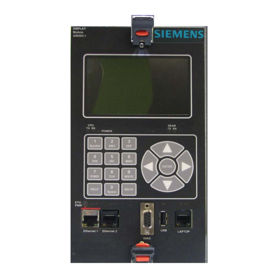
Page 10: Gcp Display Module Controls, Indicators, Connectors, And Display
INTRODUCTION _________________________________________________________________________________________________________ 1.1.1 GCP Display Module Controls, Indicators, Connectors, and Display The GCP Display module controls, indicators, connectors, and display are shown in Figure 1-2 and described in Table 1-1. DISPLAY Module A80485-2 (M9) Display SEAR Power LED TX RX LEDS TX RX LEDS SEAR TX RX... -
Page 11: Table 1-1 Display Module Controls, Indicators, Connectors, And Display Descriptions
Ethernet 1 and Ethernet 2 ports are not available on the GCP4000, therefore these ports on the Display module are not useable. NOTE The Ethernet 1 powered connector is designed specifically for Siemens Ethernet Spread Spectrum Radios and may not power other Power-Over-Ethernet (POE) devices. SIG-QG-17-05 DECEMBER 2017... -
Page 12: Resource Documents
INTRODUCTION _________________________________________________________________________________________________________ RESOURCE DOCUMENTS The GCP manuals and guidelines listed in Table 1-2 will provide complete and detailed information for the configuration and operation of your GCP unit. This quick start guide is a supplemental document to be used in concert with the product manuals listed in Table 1-2. Table 1-2 Resource Documents DOCUMENT NUMBER TITLE... -
Page 13: Section 2 - Configuration
CONFIGURATION _________________________________________________________________________________________________________ SECTION 2 - CONFIGURATION CONFIGURATION The GCP Display module default settings will normally suffice for the majority of GCP installations. This section will show some of the initial display programming options to enable the user to customize the display serial and Ethernet ports. DISPLAY MODULE MAIN SCREENS The display module main screens serve as the starting point for setup and operation of the GCP system. -
Page 14: Keypad/Navigation Cluster
CONFIGURATION _________________________________________________________________________________________________________ KEYPAD/NAVIGATION CLUSTER The Keypad and Navigation Cluster shown in Figure 2-3 is the local user interface to enter data and navigate through the display menu structure. The BACK key returns to one of the main screens. The HELP key will bring up Help screens to assist the user with hints and additional information when available. -
Page 15: Serial Port
CONFIGURATION _________________________________________________________________________________________________________ NOTE Display screens vary between GCP models and unit configuration. The following screen examples in this quick start guide are shown for general reference purposes. Refer to the applicable manual listed in Section 1.2 for the screens used by your GCP model. SERIAL PORT The GCP Display has a serial port (Diag) used for diagnostic functions and transferring software updates to other modules in the GCP case. -
Page 16: Ethernet Ports
* Denotes default setting NOTE The Ethernet 1 powered connector is designed specifically for Siemens Ethernet Spread Spectrum Radios and may not power other Power-Over-Ethernet (POE) devices. 2.4.1 Ethernet Port Configuration The Laptop Ethernet port has three modes: Server, Client, and Disabled. The Ethernet 1 and Ethernet 2 ports have two modes: Disabled and Client. -
Page 17: Server Mode
CONFIGURATION _________________________________________________________________________________________________________ 2.4.1.1 Server Mode The Server mode is only available on the Laptop port. When connecting a laptop to the display module, set the laptop’s Ethernet DHCP as a client. The display module, acting as a DHCP server, will assign an IP address to the laptop and establish communications. WARNING DO NOT CONNECT A NETWORK TO THE LAPTOP ETHERNET PORT IF THE PORT HAS BEEN CONFIGURED AS A SERVER... - Page 18 CONFIGURATION _________________________________________________________________________________________________________ 3. The Laptop DHCP Configuration default setting is Server. To Configure the port to either a client mode or to disable the port, press the ENTER key. 4. From the DHCP Configuration screen, select the desired mode using the navigation keys and press the ENTER key.
-
Page 19: Ethernet Ports 1 And 2 Setup
CONFIGURATION _________________________________________________________________________________________________________ 2.4.1.5 Ethernet Ports 1 and 2 Setup (GCP3000+ and GCP5000 only) Ethernet ports 1 and 2 have two modes available, Disabled and Client. The default setting is disabled. To reconfigure the Ethernet 1 or 2 ports, use the following procedure: 1. -
Page 20: Dns (Domain Name System) Setup
CONFIGURATION _________________________________________________________________________________________________________ 2.4.1.6 DNS (Domain Name System) Setup The Display DNS setup has three default server addresses. The user can reconfigure up to three of these addresses to match their network operations. Refer to the GCP manual for further instructions on setting DNS servers. 2.4.1.7 Ethernet Port Status The status of the Display module Ethernet ports can be viewed by selecting the Status tab on... -
Page 21: Section 3 - Operation
Using a web browser on the laptop, enter the Display IP address (192.168.255.81) in the browser address text box to connect to the display. The Siemens Web User Interface (Web UI) will appear on the computer web browser. Refer to the GCP manual for your GCP unit for further information on using the Web UI. -
Page 22: Usb Operation
PAC files or MCFs to be uploaded should be placed under the GCP4000\Applications. Executive software to be uploaded should be placed under the GCP4000\Executives. Downloaded files are placed under the Siemens\<DOT#>-<Sitename>\GCP4000 folder. NOTE Due to the software commonality, the USB Display device utilizes... -
Page 23: Usb Menu
OPERATION _________________________________________________________________________________________________________ 3.2.2 USB Menu To activate the USB Menu, insert a USB drive, with the created file structure, into the USB port on the front of the Display module as shown in Figure 3-2. DISPLAY Module A80485-2 (M9) SEAR TX RX TX RX TX RX... -
Page 24: Usb Menu
OPERATION _________________________________________________________________________________________________________ 3.2.4 USB Menu The USB menu has eight sub-menus shown in Figure 3-4 and Figure 3-5. The Software Updates menu has two sub-menus, one for software updates for modules and the second for the Display module Executive software update. The other USB menu sub-menus provide for downloading of configuration reports, display/event logs, GCP logs, train history, and uploading or downloading configuration files. -
Page 25: Module Software Updates
OPERATION _________________________________________________________________________________________________________ MODULE SOFTWARE UPDATES Module Software updates are performed using a USB Drive connected to the Display USB port or using a Laptop connected to the Display module Laptop port. Transfer of the software to individual modules is accomplished using the Display module Diag serial port. Connect a DB-9 male to DB-9 male serial cable with a Null Modem adapter between the Display module Diag port and the Diag port of the GCP module receiving the software update as shown in Figure 3-6. -
Page 26: Display Module To Ethernet 1 Port Power-Over-Ethernet (Poe) Device Connection
Power-Over-Ethernet (POE) devices. 3.4.1 Display Module to Ethernet 1 Port Power-Over-Ethernet (POE) Device Connection An example of an Ethernet 1 port Power-Over-Ethernet device connection using the Siemens Ethernet Spread Spectrum Radio is shown in Figure 3-7. Connection from the GCP Display to the Ethernet powered device is usually connected using an Ethernet cable that is provided with the Ethernet device. -
Page 27: Ethernet Network Connection
OPERATION _________________________________________________________________________________________________________ ETHERNET NETWORK CONNECTION The GCP unit can be remotely accessed using an Ethernet network connection. Ethernet 1 and Ethernet 2 ports on the Display module are generally used for such a connection, however, the Laptop port can be used for this purpose as well using a RJ-45 to RJ-45 Ethernet cable. Set the port to be used to the Client mode (see Section 2.4.1.5 for details or for the Laptop port see Section 2.4.1.4), the external network will assign the Display module an IP address and establish communications. - Page 28 OPERATION _________________________________________________________________________________________________________ This Page Intentionally Left Blank SIG-QG-17-05 DECEMBER 2017 Version No.: A...
- Page 29 NOTES...
- Page 30 NOTES...
- Page 31 NOTES...
- Page 32 Siemens Industry, Inc. Rail Automation 2400 Nelson Miller Parkway Louisville, Kentucky 40223 (502) 618-8800 Siemens Industry, Inc. Rail Automation 700 East Waterfront Drive Munhall, Pennsylvania 15120 (412) 461-2501...
Need help?
Do you have a question about the A80485-1 and is the answer not in the manual?
Questions and answers