Emerson Daniel 3410 Series Installation Manual
Gas ultrasonic flow meters
Hide thumbs
Also See for Daniel 3410 Series:
- Operation manual (192 pages) ,
- Installation manual (140 pages) ,
- Instructions for use, maintenance and installation manual (110 pages)

Related Manuals for Emerson Daniel 3410 Series


Summary of Contents for Emerson Daniel 3410 Series
- Page 1 Installation manual DAN-20057315, Rev AC June 2019 ™ Daniel 3410 Series Gas Ultrasonic Flow Meters Model 3418...
- Page 3 Email • Customer Service: DanielCST.Support@Emerson.com • Customer Support: Daniel.TechnicalSupport@Emerson.com • Field Lifecycle Services: Tech.Service@Emerson.com • Asia-Pacific: danielap.support@emerson.com • Europe: danielEMA.cst@emerson.com Return Material Authorization (RMA) A Return Material Authorization (RMA) number must be obtained prior to returning any equipment for any reason. Access and fill in the RMA form for Daniel products clicking on the link below.
- Page 4 Signal words and symbols Pay special attention to the following signal words, safety alert symbols and statements: Safety alert symbol This is a safety alert symbol. It is used to alert you to potential physical injury hazards. Obey all safety messages that follow this symbol to avoid possible injury or death.
- Page 5 • Verify that this is the correct instruction manual for your Daniel product. If this is not the correct documentation, contact Daniel at 1-713-827-6314. You may also download the correct manual from: https://www.emerson.com/en-us/automation/ daniel. • Save this instruction manual for future reference.
- Page 6 • Verify that this is the correct instruction manual for your Daniel product. If this is not the correct documentation, contact Daniel at 1-713-827-6314. You may also download the correct manual from: https://www.emerson.com/en-us/automation/ daniel. • Read and understand all instructions and operating procedures for this product.
- Page 7 Notice THE CONTENTS OF THIS PUBLICATION ARE PRESENTED FOR INFORMATIONAL PURPOSES ONLY, AND WHILE EVERY EFFORT HAS BEEN MADE TO ENSURE THEIR ACCURACY, THEY ARE NOT TO BE CONSTRUED AS WARRANTIES OR GUARANTEES, EXPRESSED OR IMPLIED, REGARDING THE PRODUCTS OR SERVICES DESCRIBED HEREIN OR THEIR USE OR APPLICABILITY. ALL SALES ARE GOVERNED BY DANIEL'S TERMS AND CONDITIONS, WHICH ARE AVAILABLE UPON REQUEST.
- Page 8 Warranty and Limitations 1. LIMITED WARRANTY: Subject to the limitations contained in Section 2 herein, Daniel Measurement & Control, Inc. (“Daniel”) warrants that the licensed firmware embodied in the Goods will execute the programming instructions provided by Daniel, and that the Goods manufactured by Daniel will be free from defects in materials or workmanship under normal use and care and Services will be performed by trained personnel using proper equipment and instrumentation for the particular Service provided.
-
Page 9: Table Of Contents
1.6 Design of Daniel 3410 series meter....................15 1.7 Meter specifications for 3418 model....................17 1.8 Preinstallation considerations......................25 1.9 Safety considerations........................25 1.10 Certifications and approvals for the Daniel 3410 series..............26 1.11 FCC compliance..........................27 1.12 References........................... 27 Chapter 2 Mechanical installation.................... - Page 10 Contents Installation manual June 2019 DAN-20057315 Installation manual...
-
Page 11: Chapter 1 Introduction
Software for Gas and Liquid Ultrasonic Flow Meters Quick Start Manual • P/N DAN-20057317 Daniel 3410 Series Ultrasonic Gas Flow Meter Maintenance and Troubleshooting Manual Daniel 3418 Gas Ultrasonic Flow meter is an 8-path chordal design, allowing the meter to cancel out the effects of swirl and cross flow. -
Page 12: Acronyms, Abbreviations And Definitions
Ethernet access • On-board LED status indicators • Analog pressure and temperature inputs ™ • Communication via Emerson’s AMS Device Manager and Field Communicator • API Chapter 21 compliant event and data logging (gas meters) ™ ® • Daniel MeterLink... - Page 13 Installation manual Introduction DAN-20057315 June 2019 Acronym or abbreviation Definition analog-to-digital converter Analog Input ® Device Manager Asset Management Software - Device Manager Analog Output ASCII MODBUS A Modbusprotocolmessageframingformat in which ASCII charactersareusedtodelineatethebeginningandendofthefr ame.ASCIIstandsforAmericanStandardCodeforInformatio nInterchange. boolean A typeofdatapointthatcan only takeonvaluesofTRUEorFALSE(generallyTRUEisrepresented by a valueof 1,FALSE is represented by a valueof 0) Bits Per Second (baud rate) cPoise...
- Page 14 Introduction Installation manual June 2019 DAN-20057315 Acronym or abbreviation Definition Local Area Network Light-emitting Diode meter (length unit) m 3 /d cubic meters per day (volumetric flow rate) m 3 /h cubic meters per hour (volumetric flow rate) m 3 /s cubic meters per second (volumetric flow rate) milliamp (current unit) MAC Address...
-
Page 15: Daniel Meterlink Software
Design of Daniel 3410 series meter Daniel 3410 Series Gas Ultrasonic Flow Meters are designed to accurately measure products in applications where reliable performance is critical, by measuring the difference in signal transit time with and against the flow across one or more measurement path(s). - Page 16 Introduction Installation manual June 2019 DAN-20057315 The 3418 combines the power of two interlocked 4-path British Gas design meters in one flowmeter body. The second set of chords is the mirror image of the first, which allows the meter to cancel out the effects of swirl and cross flow. The meter offers bidirectional measurement and superior low-flow capabilities, without the compromises associated with conventional technologies.
-
Page 17: Meter Specifications For 3418 Model
Installation manual Introduction DAN-20057315 June 2019 Figure 1-3: Transmitter electronics enclosure with local display and glass endcap All Daniel ultrasonic flow meter's U.L. safety listing is accomplished through the combination of an explosion-proof transmitter electronics enclosure that houses the CPU module, Power Supply board, I.S. - Page 18 Introduction Installation manual June 2019 DAN-20057315 WARNING CONTENTS MAY BE HAZARDOUS The meter must be fully depressurized and drained before attempting to remove the transducer holder of T-Slot transducer assembly, or the T-200 transducer assembly. If gas or fluid begins to leak from the transducer holder of T-Slot transducer assembly, or T-200 transducer stalk assembly, stop immediately and reinstall the transducer holder or T-200 stalk assembly.
- Page 19 Installation manual Introduction DAN-20057315 June 2019 Table 1-1: Daniel model 3418 meter specifications (part 1) (continued) Daniel 3418 meter specifications Enclosure materials • ASTM B26GrA356.0T6 Aluminum — 100% conversion coated and exterior coated with a polyurethane enamel • ASTM A351 GrCF8MStainless Steel —...
- Page 20 Introduction Installation manual June 2019 DAN-20057315 Table 1-3: Daniel model 3418 meter specifications (part 2) Body and Flange Sizes and Pressure rating range U.S. Customary Units - Meter sizes 10, 12, 16, 20, 24, 30, 36 and 42 (inches) • ANSI pressure classes 300, 600, 900, 1050 and 2500 (per ANSI B16.5) •...
- Page 21 Installation manual Introduction DAN-20057315 June 2019 Table 1-3: Daniel model 3418 meter specifications (part 2) (continued) Power Meter • 10.4 VDC to 36 VDC • 11 W power consumption (15 W maximum) Serial cable • Belden #9940 or equivalent (22 gauge) —...
- Page 22 Introduction Installation manual June 2019 DAN-20057315 Table 1-4: Transducers, mounts and holders (continued) Transducer specifications Transducer type Temperature range Mount and holder type T-41 -50° C to 100° C (-58° F to 212° Standard mounts/Holders/NBR O-ring Inconel mounts/316L Holders/NBR O-ring Inconel Mounts/Inconel Holders/FKM O-ring Inconel Mounts/316L...
- Page 23 Installation manual Introduction DAN-20057315 June 2019 Table 1-5: Daniel model 3418 meter specifications (part 3) (continued) Digital Input(s) (1) Single polarity Note DI1Mode must be set to Digital Input/ Calibration Input. Analog Input(s) (2) 4-20 mA • AI-1 Temperature • AI-2 Pressure Note The analog-to-digital conversion accuracy is...
- Page 24 Introduction Installation manual June 2019 DAN-20057315 Table 1-5: Daniel model 3418 meter specifications (part 3) (continued) Frequency or Digital Output parameter pairs (see Frequency/Digital outputs) Frequency or Digital Outputs (FODO1, FODO2, FODO3, FODO4, FODO5, FODO6) source selections: • (FO1A, DO1A, FO1B, DO1B, FO2A, DO2A, FO2B, DO2B) Mode options: •...
-
Page 25: Preinstallation Considerations
• Data collection and retention procedures Safety considerations The Daniel 3410 Series Gas Ultrasonic Flow Meter is suitable for use in U.L. Class 1, Division 1, Group C and D hazardous locations. NOTICE An “X” signifies the user should contact Daniel Measurement and Control, Inc. for information on the dimensions of the flameproof joints. -
Page 26: Certifications And Approvals For The Daniel 3410 Series
Certifications and approvals for the Daniel 3410 series Daniel 3410 Series Gas Ultrasonic Flow Meters have electrical, metrology, intrinsic safety and Pressure Equipment Directive certifications and approvals by the agencies listed below. Refer to the nameplate tag on the meter body, the wiring diagram (P/N... -
Page 27: Fcc Compliance
Installation manual Introduction DAN-20057315 June 2019 — International Organization of Legal Metrology (OIML) Approval agencies • • c-UL • DEMKO • INMETRO • NEPSI • GOSTR Important Please consult Flow Lifecycle Services for Daniel products for the complete metrology approvals list. 1.11 FCC compliance This equipment has been tested and found to comply with the limits for a Class A digital... - Page 28 Introduction Installation manual June 2019 DAN-20057315 6. AGA Report No. 9, Measurement of Gas by Multipath Ultrasonic Meters, Second Edition (April 2007) Installation manual...
-
Page 29: Chapter 2 Mechanical Installation
Installation manual Mechanical installation DAN-20057315 June 2019 Mechanical installation Meter piping, lifting and mounting Refer to the following sections for piping recommendations, lifting with hoist rings and slings, mounting in heated or cooled pipelines and safety warnings and precautions. CAUTION SURFACE TEMPERATURE HAZARD The meter body and piping may be extremely hot or cold. -
Page 30: Meter Components
Meter components Daniel 3410 Series Gas Ultrasonic Flow Meters are assembled, configured and tested at the factory. The meter components include the transmitter electronics enclosure, the base electronics enclosure and the meter body with transducer assemblies. - Page 31 Installation manual Mechanical installation DAN-20057315 June 2019 WARNING CONTENTS MAY BE UNDER PRESSURE When the meter is under pressure, DO NOT attempt to remove or adjust the transducer holder of the T-Slot transducer assembly, or loosen the screws holding the T-200 transducer assembly.
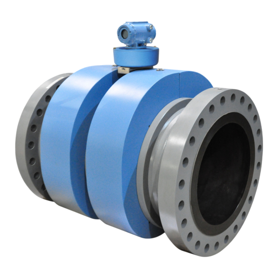
- Page 32 Mechanical installation Installation manual June 2019 DAN-20057315 The 3418 8-path ultrasonic meter components are shown below: Figure 2-1: Daniel 3418 Flow Meter assembly A. Explosion-proof transmitter enclosure (CPU Module, Power Supply, I.S. Barrier Board Backplane board) (Optional: glass endcap for Local Display) B.
- Page 33 Installation manual Mechanical installation DAN-20057315 June 2019 Figure 2-2: Transmitter electronics enclosure with optional local display and glass endcap A. Transmitter electronics enclosure with glass endcap B. Local display Model 3418 GUSM...
-
Page 34: Piping Recommendations
Mechanical installation Installation manual June 2019 DAN-20057315 Piping recommendations WARNING BURST HAZARD Before pipeline cleaning and maintenance ("pigging operations"), remove straightening vanes or flow conditioners. Failure to comply may cause excessive pressure in the meter system, resulting in death, serious injury or equipment damage. Figure 2-3: 3410 Series Gas Ultrasonic Flow Meter with flow conditioner for uni- directional flow Figure 2-4: 3410 Series Gas Ultrasonic Flow Meter with flow conditioner for bi-... - Page 35 • P = Pressure measurement location • T = Temperature measurement location (1) For best results, flow conditioning is recommended (2) D = Nominal pipe size in inches (i.e., 6 in pipe; 10D = 60 in) http://www.emerson.com/en-us/catalog/ultrasonic/daniel-3410-electronics Model 3418 GUSM...
-
Page 36: Pre-Installation Inspection
Daniel Gas Ultrasonic Flow Meter link, click the Documentation tab, expand the Data Sheets - Bulletins - Catalogs tab, then select the Data Sheet. • Daniel 3410 Series Ultrasonic Gas Flow Meters should be mounted in horizontal piping with the chord paths horizontal. CAUTION FAULTY METER INSTALLATION Correctly install the equipment. - Page 37 Installation manual Mechanical installation DAN-20057315 June 2019 DANGER LIFTING A DANIEL ULTRASONIC METER WITH OTHER EQUIPMENT The following lifting instructions are for installation and removal of the Daniel Ultrasonic Meter ONLY. The instructions below do not address lifting the Daniel ultrasonic meter while it is attached, bolted, or welded to meter tubes, piping, or other fittings.
- Page 38 Mechanical installation Installation manual June 2019 DAN-20057315 Figure 2-7: Meter end flange with tapped flat-counterbore hole for hoist ring A. Plug bolt B. Flat Counterbore surface Figure 2-8: Safety approved hoist ring Installation manual...
- Page 39 Installation manual Mechanical installation DAN-20057315 June 2019 Figure 2-9: Non-compliant eye bolt Safety precautions using safety engineered swivel hoist rings Read and follow the Safety Precautions listed below. Procedure 1. Meters must only be lifted by personnel properly trained in the safe practices of rigging and lifting.
- Page 40 Mechanical installation Installation manual June 2019 DAN-20057315 Figure 2-10: Correct sling attachment for Shell Shroud meters 9. NEVER allow the slings to contact the electronics enclosure. Damage to the enclosure may occur. Use a spreader bar with the slings to prevent contact with the electronics enclosure and the base enclosure (see Safety precautions using appropriate rated lifting...
- Page 41 Installation manual Mechanical installation DAN-20057315 June 2019 Figure 2-11: Incorrect sling attachment 10. NEVER apply shock loads to the meter. Always lift the meter gradually. If shock loading ever occurs, the hoist ring must be inspected per manufacturer's recommendations prior to any further service. If a proper inspection cannot be performed, discard the hoist ring.
- Page 42 The following instructions are intended to provide general guidelines for using proper lifting slings when lifting a Daniel 3410 Series Gas Ultrasonic Flow Meter by itself. These instructions are intended to be followed in addition to your company's standards or the DOE-STD-1090-2004 Hoisting and Rigging standard if such company standards do not exist.
- Page 43 Installation manual Mechanical installation DAN-20057315 June 2019 Safety precautions using appropriate rated lifting slings Procedure 1. Meters must only be lifted by personnel properly trained in the safe practices of rigging and lifting. 2. NEVER attempt to lift the meter by wrapping slings around the electronics enclosure.
- Page 44 Mechanical installation Installation manual June 2019 DAN-20057315 and temporarily remove the head from the meter during the lifting operation (Remove the two bolts holding the enclosure to its base and unplug the cable from the Acquisition Module. Two screws hold this cable in place.) Use a spreader-bar on the slings to prevent contact with the electronics.
-
Page 45: Mounting Requirements In Heated Or Cooled Pipelines
June 2019 Mounting requirements in heated or cooled pipelines The ambient operating temperature of the Daniel 3410 Series Gas Ultrasonic Flow Meter electronics (i.e. Flameproof enclosure and Intrinsically safe base enclosure) is -40° C (-40° F) to +60° C (+140° F). - Page 46 Mechanical installation Installation manual June 2019 DAN-20057315 Installation manual...
-
Page 47: Chapter 3 Electrical Installation
Installation manual Electrical installation DAN-20057315 June 2019 Electrical installation Cable length TTL mode The maximum cable length is 2000 feet when the Digital Output “TTL” mode is selected. Cable length Open Collector mode For the Digital Output “open collector” mode, the maximum cable length depends on the cable parameters, pull-up resistance used, the maximum frequency to output, and frequency input parameters being driven. -
Page 48: Grounding Meter Electronics Housing
Electrical installation Installation manual June 2019 DAN-20057315 Grounding meter electronics housing The meter electronics should be internally grounded for intrinsically safe operations. Connect a wire to the chassis ground lug installed inside the Transmitter Electronics Enclosure as the primary ground. A secondary ground is located outside of the Transmitter Electronics Enclosure (see Figure 3-2). -
Page 49: Conduit Seals
Installation manual Electrical installation DAN-20057315 June 2019 Figure 3-2: External ground lug A. External ground lug Conduit seals Conduit seals are required for meter installations in hazardous environments. Adhere to safety instructions to protect personnel and equipment. WARNING EXPLOSION HAZARD To reduce the risk of an explosion or fire, conduit runs must have a sealing fitting connected within 457.2 mm (18 inches) of the enclosure. - Page 50 Electrical installation Installation manual June 2019 DAN-20057315 WARNING HAZARDOUS VOLTAGE INSIDE Do not open the Transmitter Electronics Enclosure when an explosive gas atmosphere is present. Disconnect equipment from supply circuit before opening the enclosure. Failure to remove power may result in serious death or injury. 3.
- Page 51 Installation manual Electrical installation DAN-20057315 June 2019 Figure 3-3: Electronics field wiring - upper terminal block, switches, ground lug - Type 2 CPU Module A. Conduit wiring entry (four entries) c. Analog In B. Switches: • Analog In (AI1) 1. Port A —...
- Page 52 Electrical installation Installation manual June 2019 DAN-20057315 Figure 3-4: Transmitter electronics field wiring lower terminal block - Type 2 CPU Module A. Lower Terminal Block d. Ethernet a. FODO Group 1 connections • Ethernet (orange and white wire) • FODO1 •...
- Page 53 Installation manual Electrical installation DAN-20057315 June 2019 Figure 3-5: Electronics field wiring - upper terminal block, switches, ground lug - Type 4CPU Module A. Conduit wiring entry (four entries) b. Analog In B. Switches: • Analog In (AI1) 1. Port A —...
- Page 54 Electrical installation Installation manual June 2019 DAN-20057315 Figure 3-6: Transmitter electronics field wiring lower terminal block - Type 4 CPU Module A. Lower Terminal Block d. Ethernet a. FODO Group 1 connections • Ethernet (orange and white wire) • FODO1 •...
- Page 55 Installation manual Electrical installation DAN-20057315 June 2019 Engineering drawings), Daniel MeterLink Software for Gas and Liquid Ultrasonic Meters Quick Start Manual (P/N 3-9000-763) and use the Daniel MeterLink Field Setup Wizard to complete the configuration. 7. Verify the field connections are working correctly. Allow the system to run for the time specified by the customer (usually one week) and an electrician has fully tested the connections.
-
Page 56: Wiring And Inputs/Outputs
DAN-20057315 Wiring and inputs/outputs Daniel MeterLink uses the TCP/IP protocol to communicate with the Daniel 3410 Series Ultrasonic Gas Flow Meter electronics instead of Modbus ASCII or RTU. The TCP/IP protocol only works across either Ethernet, RS-485 full duplex (4-wire) or RS-232. Daniel MeterLink can communicate with multiple meters if they are multi-dropped using 4-wire, full duplex RS-485 mode. - Page 57 Installation manual Electrical installation DAN-20057315 June 2019 Figure 3-7: CPU Module labeling and LED indicators - Type 2 A. Acquisition/Measurement mode B. Power C. LED 5 - communication between CPU and Acquisition Module D. LED 4 - link between CPU and Acquisition Module E.
- Page 58 Electrical installation Installation manual June 2019 DAN-20057315 Table 3-2: CPU Module labeling and LED functions CPU Module Function Switch position indicator or LED label or LED WRITE PROT. Switch position • Write-protect mode - with switch in the ON position (default •...
- Page 59 Ethernet wiring. It is strongly recommended that the meter be configured using an independent (off- network) single host. After configuration of the Daniel 3410 Series Gas Ultrasonic Flow Meter, the DHCP option must be turned off if used on a LAN/WAN.
- Page 60 DAN-20057315 User is responsible for ensuring that physical access and Ethernet or electronic access to the Daniel 3410 Series Gas Ultrasonic Flow Meter is appropriately controlled and any necessary security precautions are implemented; such as, establishing a firewall, setting password permissions and/or implementing security levels.
- Page 61 Installation manual Electrical installation DAN-20057315 June 2019 Serial connections Use a serial cable, Daniel P/N 3-2500-401, to connect to a PC running Daniel MeterLink. The cable is designed for RS-232 communications which is the serial Port A default configuration (see Engineering drawings field wiring diagram, Daniel Drawing DMC-005324).
- Page 62 RS-485 2-wire connections use TX+ and TX - on the CPU Module Denotes auto-detected protocols NOTICE If not using Ethernet, a full duplex serial connection is necessary for Daniel MeterLink to communicate with a Daniel 3410 Series Gas Ultrasonic Meter. Installation manual...
- Page 63 June 2019 Figure 3-9: PC to meter serial connection wiring 3.5.2 Input/output connections The Daniel 3410 Series Gas Ultrasonic Flow Meter provides the I/O connections on the CPU Module. Figure 3-10: CPU Module I/O connections A. Frequency/Digital Output 2 B. Frequency/Digital Output 3 C.
- Page 64 Electrical installation Installation manual June 2019 DAN-20057315 Figure 3-11: CPU Module I/O connections - Type 4 A. Frequency/Digital Output 2 B. Frequency/Digital Output 3 C. Frequency/Digital Output 4 D. Frequency/Digital Output 5 E. Analog Input - Temperature and pressure connections Optional input and output modules These modules are plugged into the second or third slot (retrofit) on the electronics head.
- Page 65 Installation manual Electrical installation DAN-20057315 June 2019 Figure 3-12: Optional module RS-232 A. Serial COMs (RS-323) B. RS-232: RTS, TX, RX Model 3418 GUSM...
- Page 66 Electrical installation Installation manual June 2019 DAN-20057315 Figure 3-13: Optional module RS-485 A. Serial COMs (RS-485) B. RS-485: TX+, TX- (2-wire Half Duplex) Installation manual...
- Page 67 Installation manual Electrical installation DAN-20057315 June 2019 Figure 3-14: Optional Expansion I/O Module A. Expansion I/O Module • B. RS-232: RX, TX, COM • B. RS-485: TX+, TX- (2-wire Half Duplex) • C. 4-20mA Input - AI3+/- (future use) • D.
- Page 68 Electrical installation Installation manual June 2019 DAN-20057315 Table 3-5: Expansion I/O to RJ45 wiring Ethernet communication Wire color CPU/EXP White w/Green Stripe Solid Green White w/Orange stripe Solid orange Note Wiring colors for TX+/TX- and RX+/RX- can be switched as ethernet ports will automatically detect crossover vs.
- Page 69 Installation manual Electrical installation DAN-20057315 June 2019 Figure 3-16: Transmitter Head with Expansion I/O Module A. Ethernet connection from Expansion I/O Module B. Ethernet connection available for user connection C. Ethernet connection available for user connection D. Ethernet connection from CPU Module E.
- Page 70 Electrical installation Installation manual June 2019 DAN-20057315 Table 3-6: Optional modules parameters Description Common features Port B/Port C • Typically used for general • Communications via Daniel (Optional communications with a flow MeterLink using RS-232 module) computer, RTU (Modbus slave) •...
- Page 71 Installation manual Electrical installation DAN-20057315 June 2019 D. Ethernet switch port 3 - Link/Activity Flashing (Green) indicator Table 3-7: Expansion I/O LED functions Expansion I/O Module LED Function TX/RX RX/TX signal (Port B/C for • Flashing Orange - RX RS485 or RS232 •...
- Page 72 Electrical installation Installation manual June 2019 DAN-20057315 • Digital output 2A is based on Digital output 2A content (Frequency Output 1Validity, Flow Direction, Process Validity) • Digital output 2B is based on Digital output 2B content (Frequency Output 1Validity, Flow Direction, Process Validity) Frequency or Digital Outputs (FODO2, FODO3, FODO4, FODO5) source options ∼...
- Page 73 Installation manual Electrical installation DAN-20057315 June 2019 • Bidirectional - output reports flow on Phase A only in the forward direction and on Phase B only in the reverse direction. Maximum frequency for the frequency outputs • 1000Hz • 5000Hz Frequency/Digital output Source configuration Frequency /Digital Output 1...
- Page 74 (Group 2) Analog input settings The Daniel 3410 Series Gas Ultrasonic Flow Meter has the capability to sample analog temperature (Analog Input 1) and pressure (Analog Input 2) with 4-20 mA signals. These analog input signals are configured to sink. The two independent analog input circuits are configured for conventional 4-20 mA service.
- Page 75 June 2019 Digital input The Daniel 3410 Series Gas Ultrasonic Flow Meter provides one digital input that can be used as a general purpose input. The digital input must be configured via the Daniel MeterLink Tools|Edit/Compare Configuration screen. DI1Mode must be set to Digital Input/Calibration Input.
-
Page 76: Security Seal Installation
Electrical installation Installation manual June 2019 DAN-20057315 Figure 3-20: CPU Module power source connections A. Power In connector (main power) B. 24V LOOP POWER C. 2 Amp fuse (used for the main power input) Security seal installation Security seals protect the integrity of the meter metrology and prevent tampering with transducer assemblies. - Page 77 Installation manual Electrical installation DAN-20057315 June 2019 Procedure 1. Rotate the end caps clockwise fully closing and compressing the end cap seal. Install the Security latch for each end cap using a 3mm Allen wrench. 2. Install the security seal wire into and through one of the two holes in the end cap. a) Choose holes that minimize counterclockwise rotation of the end cap when the security wire is taut (maximum wire diameter .078 inch;...
- Page 78 Electrical installation Installation manual June 2019 DAN-20057315 Figure 3-23: Base Enclosure wire seal installation A. Security wire seals B. Base enclosure cover 2. Position the wire to prevent counterclockwise rotation of the screws when the seal wire is taut. 3. Feed the security wire beneath the Transmitter Electronics Enclosure and through the adjacent socket head screw.
- Page 79 Installation manual Electrical installation DAN-20057315 June 2019 Figure 3-24: Latch pin and Shroud recesses A. Shroud pin on the meter body 2. Hook the appropriate shroud over the pin, ensuring the transducer cabling is within the shroud. Care needs to be taken not to pinch the cables between the shroud recesses and shroud as the shroud is fitted into place.
- Page 80 Electrical installation Installation manual June 2019 DAN-20057315 Figure 3-25: Shroud hanging on Shroud pin 3. Bring up the mating shroud, ensuring the transducer cabling falls within and is snug in the shroud recess as before and hold in place. 4. Latch first the bottom shroud latch(s) followed by those on the upper side of the shroud.
-
Page 81: Sealing The Unit
Installation manual Electrical installation DAN-20057315 June 2019 6. Check that the seal is properly fitted to prevent the latch from lifting. Verify the latch is secure and clip off any extra wire extending from the seal. Sealing the unit The unit should be properly sealed after electrical connections have been tested according to the customer's Best Practices schedule. - Page 82 Electrical installation Installation manual June 2019 DAN-20057315 Installation manual...
-
Page 83: Chapter 4 Configuration
Installation manual Configuration DAN-20057315 June 2019 Configuration After the mechanical and electrical installation is complete use the following to install ™ MeterLink in order to establish connection with the meter to perform final configuration and verify meter performance. ™ Set up the Daniel MeterLink Procedure ™... - Page 84 Configuration Installation manual June 2019 DAN-20057315 excitation voltage and pull-up resistor or TTL mode which outputs a 0-5 VDC signal. b) Select Next to continue to Frequency Outputs page. Note Frequency outputs 1 and Digital outputs 1 are paired together meaning the Digital outputs 1 will report the status for the parameter for Frequency outputs 1.
- Page 85 Installation manual Configuration DAN-20057315 June 2019 10. Select the settings below to configure a serial port as a Modbus Master to poll a gas chromatograph. See Serial Connections to configure port as Read-only. • Serial Port: select which serial port will be connected to the GC. While the port is configured for communications to a GC, it will not act as a Modbus slave device ™...
- Page 86 Configuration Installation manual June 2019 DAN-20057315 a) Click Next to continue to the Continuous Flow Analysis page, if View Continuous Flow Analysis setup was selected on the Startup page. 13. Configure the Continuous Flow Analysis (optional). This page is only displayed for Daniel Gas Ultrasonic meters if both temperature and pressure are set to Live Analog, Fixed and Base condition correction is selected on the Startup Page.
- Page 87 Installation manual Configuration DAN-20057315 June 2019 Table 4-1: Local display labels, descriptions and valid units (continued) Local display labels, descriptions and valid units • ACF – Actual Cubic Feet • ACM – Actual Cubic Meters • MACF – Thousand Actual Cubic Feet •...
- Page 88 Configuration Installation manual June 2019 DAN-20057315 Table 4-1: Local display labels, descriptions and valid units (continued) Local display labels, descriptions and valid units QBASE — Corrected volume flow rate • SCF – Standard Cubic Feet • SCM – Standard Cubic Meters •...
- Page 89 Installation manual Configuration DAN-20057315 June 2019 Table 4-1: Local display labels, descriptions and valid units (continued) Local display labels, descriptions and valid units • -SCF – Standard Cubic Feet • -SCM – Standard Cubic Meters • -MSCF – Thousand Standard Cubic Feet •...
- Page 90 Configuration Installation manual June 2019 DAN-20057315 Table 4-1: Local display labels, descriptions and valid units (continued) Local display labels, descriptions and valid units • CF – Cubic Feet • CM –Cubic Meters • MCF – Thousand Cubic Feet • MCM –Thousand Cubic Meters AO1 —...
-
Page 91: Security Seals For The Meter
Installation manual Configuration DAN-20057315 June 2019 Procedure 1. Select Finish to write the configuration settings to the meter. 2. Save the meter configuration file, collect a Maintenance log and Waveforms to document the “As Left” settings. Security seals for the meter For the integrity of the meter metrology and to prevent tampering with the transmitter electronics and transducer assemblies, attach security latches on the end caps and install security wires, if required, on the Transmitter Electronics Enclosure end caps, the Bracket/... - Page 92 Configuration Installation manual June 2019 DAN-20057315 Installation manual...
-
Page 93: Appendix A Engineering Drawings
Installation manual Engineering drawings DAN-20057315 June 2019 Engineering drawings 3410 Series engineering drawings This appendix contains the following engineering drawing(s) for the ultrasonic meter: DMC-005324 Daniel 3410 Series Ultrasonic Gas Flow Meter System Wiring Diagram Model 3418 GUSM... - Page 98 Engineering drawings Installation manual June 2019 DAN-20057315 Installation manual...
-
Page 99: B.1 List Of Source Codes For Executable Files
Installation manual Open source licenses DAN-20057315 June 2019 Open source licenses List of source codes for executable files Source code for executable files or libraries included in this product is provided per the indicated license in the table below. Hyperlinks to the controlling organization's websites are included through Section B.1. - Page 100 Unsorted BlockImage Device vsftpd-2.2.2-1 vsftpd vsftpd - VerySecureFtp Daemon zlib-1.2.3-2 zlib zlib Distribution zlib compression utilities and libraries Follow the link below to the Daniel Ultrasonic Products webpage for additional open source information and zipped source code files. https://www.emerson.com/en-us/catalog/daniel-3415 Installation manual...
- Page 101 Installation manual Open source licenses DAN-20057315 June 2019 B.1.1 GNU General Public License For more details about GNU GPL (General Public License), follow the link below: http://www.gnu.org/ ™ Daniel Measurement and Control, Inc., uses GPL version 2. http://www.gnu.org/licenses/old-licenses/gpl-2.0.html The GNU GPL is currently version 3 http://www.gnu.org/licenses/quick-guide-gplv3.html For older versions of the GNU General Public License, follow the link below: http://www.gnu.org/licenses/old-licenses/old-licenses.html#GPL...
- Page 102 Open source licenses Installation manual June 2019 DAN-20057315 Also, for each author's protection and ours, we want to make certain that everyone understands that there is no warranty for this free software. If the software is modified by someone else and passed on, we want its recipients to know that what they have is not the original, so that any problems introduced by others will not reflect on the original authors' reputations.
- Page 103 Installation manual Open source licenses DAN-20057315 June 2019 These requirements apply to the modified work as a whole. If identifiable sections of that work are not derived from the Program, and can be reasonably considered independent and separate works in themselves, then this License, and its terms, do not apply to those sections when you distribute them as separate works.
- Page 104 Open source licenses Installation manual June 2019 DAN-20057315 5. You are not required to accept this License, since you have not signed it. However, nothing else grants you permission to modify or distribute the Program or its derivative works. These actions are prohibited by law if you do not accept this License. Therefore, by modifying or distributing the Program (or any work based on the Program), you indicate your acceptance of this License to do so, and all its terms and conditions for copying, distributing or modifying the Program or works based on it.
- Page 105 Installation manual Open source licenses DAN-20057315 June 2019 10. If you wish to incorporate parts of the Program into other free programs whose distribution conditions are different, write to the author to ask for permission. For software which is copyrighted by the Free Software Foundation, write to the Free Software Foundation;...
- Page 106 Open source licenses Installation manual June 2019 DAN-20057315 If the program is interactive, make it output a short notice like this when it starts in an interactive mode: Gnomovision version 69, Copyright (C) year name of author Gnomovision comes with ABSOLUTELY NO WARRANTY;...
- Page 107 Installation manual Open source licenses DAN-20057315 June 2019 The "Minimal Corresponding Source" for a Combined Work means the Corresponding Source for the Combined Work, excluding any source code for portions of the Combined Work that, considered in isolation, are based on the Application, and not on the Linked Version.
- Page 108 Open source licenses Installation manual June 2019 DAN-20057315 0) Convey the Minimal Corresponding Source under the terms of this License, and the Corresponding Application Code in a form suitable for, and under terms that permit, the user to recombine or relink the Application with a modified version of the Linked Version to produce a modified Combined Work, in the manner specified by section 6 of the GNU GPL for conveying Corresponding Source.
- Page 109 Installation manual Open source licenses DAN-20057315 June 2019 B.1.3 BSD Open Source License ™ For more details about the Open Source BSD license or the Open Source Initiative, follow the link below: http://www.opensource.org/licenses/bsd-license.php Copyright (c) <YEAR>, <OWNER> All rights reserved. •...
- Page 110 Open source licenses Installation manual June 2019 DAN-20057315 THE SOFTWARE IS PROVIDED "AS IS", WITHOUT WARRANTY OF ANY KIND, EXPRESS OR IMPLIED, INCLUDING BUT NOT LIMITED TO THE WARRANTIES OF MERCHANTABILITY, FITNESS FOR A PARTICULAR PURPOSE AND NONINFRINGEMENT. IN NO EVENT SHALL THE AUTHORS OR COPYRIGHT HOLDERS BE LIABLE FOR ANY CLAIM, DAMAGES OR OTHER LIABILITY, WHETHER IN AN ACTION OF CONTRACT, TORT OR OTHERWISE, ARISING FROM, OUT OF OR IN CONNECTION WITH THE SOFTWARE OR THE USE OR OTHER DEALINGS IN...
-
Page 111: Dan-20057315 June
Installation manual DAN-20057315 June 2019 Model 3418 GUSM... - Page 112 Daniel Measurement and Control, Inc. ("Daniel") is an Emerson Automation Solutions business unit. The Daniel name and logo are trademarks of Daniel Industries, Inc. The Emerson logo is a trademark and service mark of Emerson Electric Co. All other trademarks are the property of their respective...
Need help?
Do you have a question about the Daniel 3410 Series and is the answer not in the manual?
Questions and answers