Emerson Daniel 3415 Maintenance And Troubleshooting Manual
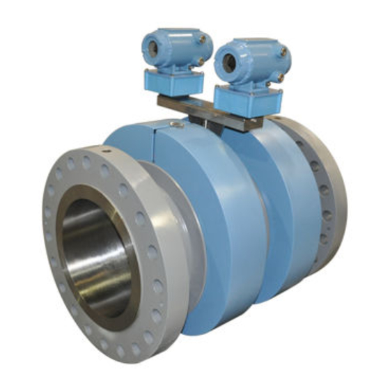
Daniel 3410 series gas ultrasonic flow meter
Hide thumbs
Also See for Daniel 3415:
- Installation manual (140 pages) ,
- Operation manual (172 pages) ,
- Maintenance and troubleshooting manual (96 pages)

Related Manuals for Emerson Daniel 3415


Summary of Contents for Emerson Daniel 3415
- Page 1 Maintenance and Troubleshooting manual P/N 3-9000-791, Rev B June 2016 ™ Daniel 3410 Series Gas Ultrasonic Flow Meters Models 3415, 3416 and 3417...
- Page 2 Houston, TX 77041 USA http://www.EmersonProcess.com Email • Customer Service: tech.service@emersonprocess.com • Customer Support: daniel.cst.support@emerson.com • Asia-Pacific: danielap.support@emerson.com • Europe: danielEMA.cst@emerson.com Return Material Authorization (RMA) A Return Material Authorization (RMA) number must be obtained prior to returning any equipment for any reason. Download the RMA form from the Support Services web page by selecting the link below.
- Page 3 Signal words and symbols Pay special attention to the following signal words, safety alert symbols and statements: Safety alert symbol This is a safety alert symbol. It is used to alert you to potential physical injury hazards. Obey all safety messages that follow this symbol to avoid possible injury or death.
- Page 4 Important safety instructions Daniel Measurement and Control, Inc. (Daniel) designs, manufactures and tests products to function within specific conditions. Because these products are sophisticated technical instruments, it is important that the owner and operation personnel must strictly adhere both to the information printed on the product and to all instructions provided in this manual prior to installation, operation, and maintenance.
- Page 5 Product operation (Personnel): • To prevent personal injury, personnel must follow all instructions of this manual prior to and during operation of the product. • Follow all warnings, cautions, and notices marked on, and supplied with, this product. • System should be designed to avoid over pressure conditions or exceeding maximum safe flow rate if meter losses measurement.
- Page 6 Notice THE CONTENTS OF THIS PUBLICATION ARE PRESENTED FOR INFORMATIONAL PURPOSES ONLY, AND WHILE EVERY EFFORT HAS BEEN MADE TO ENSURE THEIR ACCURACY, THEY ARE NOT TO BE CONSTRUED AS WARRANTIES OR GUARANTEES, EXPRESSED OR IMPLIED, REGARDING THE PRODUCTS OR SERVICES DESCRIBED HEREIN OR THEIR USE OR APPLICABILITY. ALL SALES ARE GOVERNED BY DANIEL'S TERMS AND CONDITIONS, WHICH ARE AVAILABLE UPON REQUEST.
- Page 7 Warranty and Limitations 1. LIMITED WARRANTY: Subject to the limitations contained in Section 2 herein, Daniel Measurement & Control, Inc. (“Daniel”) warrants that the licensed firmware embodied in the Goods will execute the programming instructions provided by Daniel, and that the Goods manufactured by Daniel will be free from defects in materials or workmanship under normal use and care and Services will be performed by trained personnel using proper equipment and instrumentation for the particular Service provided.
-
Page 9: Table Of Contents
Contents Contents Chapter 1 Maintenance ........................1 Precautions for meter maintenance .....................1 Field hydrostatic pressure testing procedures ................2 1.2.1 T-Slot Transducer Assembly and Mount ................ 2 Routine maintenance ........................3 1.3.1 Maintenance logs and reports ..................3 1.3.2 Pipeline cleaning maintenance ..................7 1.3.3 Visual inspection ...................... - Page 10 Contents Gas Ultrasonic Flow Meter...
-
Page 11: Chapter 1 Maintenance
Maintenance Maintenance Topics covered in this chapter: • Precautions for meter maintenance • Field hydrostatic pressure testing procedures • Routine maintenance Precautions for meter maintenance This section includes discussion of the maintenance of Daniel 3410 Series Ultrasonic Meters. For reference, you may download the Daniel MeterLink Quick Start Manual from: http://www2.emersonprocess.com/en-US/brands/daniel/Flow/ultrasonics/Pages/ MeterLink.aspx CAUTION! -
Page 12: Field Hydrostatic Pressure Testing Procedures
Maintenance CAUTION! ESCAPING FLUIDS HAZARD The purchaser of the meter is responsible for the selection of Daniel components/seals and materials compatible with the chemical properties of the measurement fluid. Failure to select suitable meter components/seals may cause escaping fluids, resulting in injury or equipment damage. -
Page 13: Routine Maintenance
Maintenance Model 3417 Quantity 2 x 1-360-01-220 Repeat Step 3 through Step 5 for the other transducer(s) being careful to note the location of each transducer in the meter assembly. Run the field hydrostatic test. Reverse the steps above to reinstall the transducers into their appropriate ports. Before reinstalling the transducer assemblies, ensure the transducer ports, mounts, and transducer holders are clean and free of debris. - Page 14 Maintenance Maintenance log collection Figure 1-1: Maintenance log collection parameters Trend maintenance log collection Merging the results of two or more Maintenance logs into a single file, allows you to build a historical database of the meter's performance. Trending the logs indicates changes from the original installation of the meter, or over time.
- Page 15 Maintenance Figure 1-2: Trend log collection This is important since many diagnostics change slowly overtime. Trending the maintenance logs helps identify these changes and makes problems much more obvious than merely viewing a single inspection report. The Trending feature is integral to Daniel ™...
- Page 16 Maintenance Figure 1-3: Archive log collection parameters The logs may be collected in a single file or you can choose to collect one type of log. Each of the Meter Archive logs include the Meter Configuration file. Gas Ultrasonic Flow Meter...
-
Page 17: Pipeline Cleaning Maintenance
Maintenance 1.3.2 Pipeline cleaning maintenance WARNING! BURST HAZARD Before pipeline cleaning and maintenance ("pigging operations"), remove straightening vanes or flow conditioners. Failure to comply may cause excessive pressure in the meter system, resulting in death, serious injury or equipment damage. Figure 1-4: 3410 Series Gas Ultrasonic Flow Meter with flow conditioner for uni- directional flow... - Page 18 Maintenance Movement of components that should be rigid. Excessive noise due to vibration could be sign of a loose component. Inspection should be more frequent in systems with a large amount of vibration. Gas Ultrasonic Flow Meter...
-
Page 19: Chapter 2 Troubleshooting
Troubleshooting Troubleshooting Meter status alarms ™ Run Daniel MeterLink and open the Meter Monitor (Summary) view to perform a diagnostics health check. Figure 2-1: Meter Monitor status alarms If the meter is measuring flow and operating within the calibration parameters the Meter Status LED is green. -
Page 20: Check Status
Troubleshooting Figure 2-2: Status summary 2.1.1 Check status Click the Check Status button if any of the LEDs are yellow or red to see more specific information causing the status alarm. Some alarms do not require an acknowledge and will clear automatically when the alarm condition goes away. -
Page 21: System Alarm
Troubleshooting • System • Power Loss • Field I/O • Validity • Comms • Check Status 2.1.2 System alarm The System alarm indicates a failure in the hardware that should be addressed by a service technician. This includes memory checksum errors and communication errors within the hardware. -
Page 22: Comms Alarm
TCP/IP commands between Daniel MeterLink and the connected meter. ® For troubleshooting communications with the 475 Field Communicator for the HART Protocol, refer to Section 5 of the Emerson 475 Field Communicator User’s Manual, Rev D. This manual may be downloaded from the following location: http://www2.emersonprocess.com/en-US/brands/Field-Communicator/Pages/ Support.aspx... -
Page 23: Chapter 3 Meter Repairs
Meter repairs Meter repairs Topics covered in this chapter: • Precautions • T-Slot transducer removal and installation • Transducer holder removal and installation • Transducer cable removal and installation • Replace the meter electronics • Acquisition Module replacement Precautions This section includes discussion of the maintenance of Daniel 3410 Series Ultrasonic Meters. - Page 24 Meter repairs NOTICE Prior to lifting the unit, refer to the Daniel 3415, 3416, or 3417 Gas Ultrasonic Flow Meter nameplate or outline dimensional (general arrangement) drawing for the assembled weight. WARNING! FLUID CONTENTS MAY BE UNDER PRESSURE When the meter is under pressure, DO NOT attempt to remove or adjust the transducer holder.
-
Page 25: T-Slot Transducer Removal And Installation
Meter repairs WARNING! CRUSHING HAZARD During meter installation or removal, always place the unit on a stable platform or surface that supports its assembled weight. Failure to comply could allow the meter to roll, resulting in serious injury or equipment damage. - Page 26 Meter repairs Remove the transformer retainer using a 1 1/8” wrench and then disconnect and remove the transformer module (Figure 3-1). Note T-21 transducers use W-01 transformers and T-22 transducers use W-02 transformers. Figure 3-1: T-21 and T-22 transducer assembly A.
-
Page 27: Install Transducers
Meter repairs Loosen the three Allen setscrews with a 1/16” hex driver securing the transducer assembly and stalk, if installed. Carefully remove the old transducer by pulling it from the T-Slot transducer holder assembly without rotating. Important Record the “L” dimension of the removed transducers which is used to update the meter configuration after all of the transducers are replaced. - Page 28 Meter repairs Note Do not apply lubricant to the transducer or stalk O-rings. NOTICE Ensure that the transducers identified as belonging to end 1 are installed on end 1 of the meter housing and those identified as belonging to end 2 are installed on end 2 of the meter housing.
- Page 29 Meter repairs Figure 3-3: T-21 and T-22 transducer assembly, holder, transformer assembly, retainer, retaining clip and transducer cable A. Mount (Inconel mount and holder) B. Transducer holder (Type - H1 P/N 1-360-01-128, H2 P/N 1-360-01-228) C. T-21 transformer module (W-01 P/N 1-360-03-090) or T-22 transformer module (W-02 P/N 1-360-03-110) D.
-
Page 30: Replace The Transformers
Meter repairs leak detector. If leaks are found, the meter must be vented to atmosphere and the problem corrected. Check for leaks again. Continue the process until there are no leaks. ™ Continue with Section 3.2.4 to use the Daniel MeterLink Transducer Swap-out Wizard. - Page 31 Meter repairs Average delay time and delta delay time modifications The transducer pair average delay time and delta delay time are located on the transducer pair calibration sheet. These values must be downloaded to the appropriate meter data points (AvgDlyA... AvgDlyD, DltDlyA... DltDlyD). The lengths of the transducers are also included on the calibration sheet and are etched on the transducers.
- Page 32 Meter repairs Figure 3-4: Daniel MeterLink Transducer Swap-out Wizard Gas Ultrasonic Flow Meter...
- Page 33 Meter repairs Chord “L” Dimension Calculation The chord “L” dimension is calculated from the meter housing length as well as the transducer pair lengths, mount lengths, holder lengths, and stalk lengths as shown in Equation Chord "L" Dimension. The transducer lengths are etched on the transducers. Likewise, the lengths of the mounts, stalk assemblies, and transducer holders are also etched on the individual components.
-
Page 34: Transducer Holder Removal And Installation
Meter repairs Equation 3-1: Chord “L” Dimension chord MeterHousing Mount1 Mount 2 − L − L − L Xdcr 1 Stalk 1 Hldr 1 − L − L − L Xdcr 2 Stalk 2 Hldr 2 chord “L” dimension (in) (LA ... LD) chord meter housing length (in) MeterHousing... - Page 35 Meter repairs following steps detail how to safely remove and reinstall them. Before removing and installing the transducer holder, connect to the meter using Daniel MeterLink and collect and save a Maintenance Log. Blow the line down according to the site standard operating procedures. Ensure that the line pressure is down to atmospheric pressure prior to disassembly.
-
Page 36: Install The Transducer Holder
Meter repairs Figure 3-5: Transducer holder length and set screw identification A. Transducer holder set screws B. Transducer holder length identification Loosen the three Allen setscrews with a 1/16” hex driver securing the transducer assembly and stalk, if installed. Carefully remove the transducer by pulling it from the T-Slot transducer holder (or stalk if installed) without rotating. - Page 37 Meter repairs Figure 3-6: Transducer holder, stalk and transducer assembly A. Transducer holder B. Stalk C. Transducer assembly Replace the O-rings and backup rings on the transducer holder. Make sure the contoured side of the backup ring faces away from the transducer holder. It is highly recommended that the O-rings be replaced when the transducer is removed from the holder/stalk.
-
Page 38: Transducer Cable Removal And Installation
Meter repairs Repeat Step 1 through Step 11 for all transducer holders to be replaced. Slowly repressurize the meter to line pressure. Check for leaks as the meter is pressurized. If you hear gas leaking from the threads, recheck all connections and resolve the problem. -
Page 39: Replace Transducer Cables
Meter repairs Figure 3-7: Daniel 3410 Series Ultrasonic Gas Flow Meter transducer cables and ports A. Cable ties B. 3410 Series Ultrasonic Meter transducer port C. Transducer assembly WARNING! CRUSHING HAZARD During meter installation or removal, always place the unit on a stable platform or surface that supports its assembled weight. - Page 40 Meter repairs Cut the tie wraps for the transducer cable you are replacing. Remove the four bolts holding the Base Enclosure cover to the Transmitter Electronics Enclosure using a 6mm Allen wrench. Lift the Transmitter Electronics Enclosure from the Base Enclosure. It may be necessary to remove the ground lug wire and loosen the conduit connections prior to removal.
-
Page 41: Replace The Meter Electronics
Meter repairs Figure 3-8: Model 3410 Ultrasonic Meter Acquisition Module Wiring Replace the meter electronics The following procedure should be performed by a qualified service technician or trained personnel. Observe all warning labels on the meter before starting this procedure. The Daniel 3410 Series Gas Ultrasonic Flow Meter Transmitter Electronics Enclosure consists of the following: •... -
Page 42: Replace Cpu Module Or Optional I/O Module
Meter repairs • Power Supply (P/N 360-03-003) • Backplane Board (P/N 360-03-007) The Daniel 3410 Series Gas Ultrasonic Flow Meter Base Enclosure consists of the following: • Acquisition Module (P/N 1-360-03-008) (T-21, T-22, T-41) • Transducer Cable (5FT P/N 1-360-03-232, 15FT P/N 1-360-03-233) Should the Daniel 3410 Series Ultrasonic Gas Flow Meter require disassembly in the field (i.e., check boards, change switch settings, or replace boards), to prevent electrostatic damage to the electronic boards, always use a ground strap while handling the circuit... - Page 43 Meter repairs Figure 3-10: CPU or I/O Module replacement A. Terminal end of Transmitter Electronics Enclosure B. CPU Module C. Optional I/O Module D. Power Supply board E. Fuse F. Internal chassis ground Maintenance and Troubleshooting manual...
- Page 44 Meter repairs Figure 3-11: CPU module Type 2 and Type 4 A. CPU Module Type 2 - side label B. CPU Module Type 4 - side label Grasp the outer ends of the module you want to replace and pull it out of the enclosure.
-
Page 45: Fuse Replacement
Meter repairs Figure 3-12: Transmitter electronic enclosure security seals A. Transmitter Electronics Enclosure end cap B. Security wire seals Adjust the security wire, removing all slack and thread into the lead seal. Cut wire ends to remove excess wire. If replacing other electronics or the fuse, continue with Section 3.5.2, Section 3.5.3... -
Page 46: Replace Backplane, I.s. Barrier Or Power Supply Board
Meter repairs Turn the fuse cap clockwise 1/8 turn using a 1/4 inch standard flat head screw driver. Replace the end cap and security latch (requires a 3 mm Allen wrench). If required, install the security seal wire into and (requires a 3 mm Allen wrench). If required, install the security seal wire into and through one of the two holes in the end cap. - Page 47 Meter repairs Figure 3-13: Backplane board replacement A. Non-terminal end of Transmitter Electronics Enclosure B. Power Supply board C. I.S. Barrier board (inside the Guide Plate) D. Acquisition cable E. Backplane board Use a 3 mm flat head screw driver and disconnect the Acquisition Cable terminal block from the Backplane.
- Page 48 Meter repairs Install the four Phillips head screws to secure the Backplane to the enclosure standoffs. Reinstall the terminal blocks on the CPU Module, Optional I/O Module (if installed), and the Power Supply board using a 3 mm flat head screw driver. NOTICE Make sure the terminal blocks are aligned with the Guide Plate openings.
- Page 49 Meter repairs Figure 3-14: I.S. Barrier board replacement A. Non-terminal end of Transmitter Electronics Enclosure B. Power Supply board C. I.S. Barrier board (inside the Guide Plate) D. Acquisition cable E. Backplane board Remove the I.S. Barrier Board from the Guide Plate on the right side of the enclosure.
- Page 50 Meter repairs Reinstall the J7 terminal block, if removed, on the Backplane board. Re-install the CPU Module, Optional I/O Module (if installed) and the Power Supply. Module, Optional I/O Module (if installed) and the Power Supply. If replacing other electronics, continue with the following procedures before replacing the end caps and sealing the enclosure.
- Page 51 Meter repairs Power Supply Board replacement If replacing the Power Supply board remove power to the meter. Disconnect the Transmitter Electronics Enclosure security seals, loosen the end cap security latches with a 3mm Allen wrench and remove both end caps (see Figure 3-15).
- Page 52 Meter repairs Figure 3-16: Power Supply board replacement A. Non-terminal end of Transmitter Electronics Enclosure B. Power Supply board C. I.S. Barrier board (inside the Guide Plate) D. Acquisition cable E. Backplane board Pull the Backplane board out of the enclosure. This disconnects the I.S. Barrier Board.
-
Page 53: Acquisition Module Replacement
Meter repairs Attach the Backplane to the enclosure standoffs with the four Phillips head screws. If the Local Display Module is installed on the Backplane, use a flat blade screw driver and install the four flat-head screws into the enclosure standoffs. Use a flat blade screw driver and install the terminal blocks on the CPU Module, Optional I/O Module, I.S. - Page 54 Meter repairs Figure 3-17: Conduit removal A. Transmitter electronics enclosure B. Conduit nuts If the meter is equipped with security seals, remove the seals from the bolts on the Base Gas Ultrasonic Flow Meter...
- Page 55 Meter repairs Figure 3-18: Transmitter Electronics Enclosure and Base Enclosure security seal removal A. Transmitter electronics enclosure B. Base enclosure bolts and security seals Use a 6 mm Allen wrench and remove the four hex head bolts securing the Transmitter Electronics Enclosure to the Base Enclosure. Maintenance and Troubleshooting manual...
- Page 56 Meter repairs Figure 3-19: Transmitter Electronics Enclosure removal A. Transmitter electronics enclosure B. Base enclosure bolts C. Base enclosure Use a 3 mm flat head screw driver and disconnect the Acquisition cable terminal block and the transducer wire terminal blocks from the Acquisition Module inside of the Base enclosure.
- Page 57 Meter repairs Figure 3-20: Acquisition Module cable and transducer wiring A. Acquisition cable B. Acquisition wiring terminal blocks C. Acquisition Module NOTICE Make sure the transducer cables are labeled for the chord configuration. Maintenance and Troubleshooting manual...
- Page 58 Meter repairs Remove the three Acquisition Module flat head screws and split lock washers, then remove the Acquisition Module from the Base Enclosure. Insert the new Acquisition Module into the Base Enclosure and secure with the three split lock washers and flat head screws. Reattach the terminal blocks onto the Acquisition Module (3 mm flat head screw driver required).
- Page 59 Meter repairs Feed the security wire beneath the Transmitter Electronics Enclosure and through the adjacent socket head screw. Twist the wire, removing all slack and seal. Figure 3-22: Base Enclosure security seals A. Transmitter Electronics Enclosure B. Transmitter Electronics endcap security latch C.
- Page 60 Meter repairs Gas Ultrasonic Flow Meter...
-
Page 61: Appendix A Conversion Factors
Conversion factors Appendix A Conversion factors Topics covered in this appendix: • Conversion factors per units of measurement • K-Factor and inverse K-Factor conversions Conversion factors per units of measurement The following table includes conversion factors for many of the Metric and U.S. Customary units of measure used with Daniel 3410 Series Ultrasonic Gas Flow Meters and Daniel MeterLink. -
Page 62: K-Factor And Inverse K-Factor Conversions
Conversion factors Table A-1: Conversion factors per units of measurement (continued) Conversion factors Unit of measurement 6.289811 bbl/m 3 10 -3 Pa•s/cPoise 1.488 Pa•s/(lb/(ft•s)) K-Factor and inverse K-Factor conversions Equation A-1: Frequency volumetric flow rate K-Factor FreqQ FullScale KFactor = ( * ) MaxFreq 3600s §... - Page 63 Conversion factors • VolUnitMetric cubic meters liters Maintenance and Troubleshooting manual...
- Page 64 Conversion factors Gas Ultrasonic Flow Meter...
-
Page 65: Appendix B Engineering Drawings
Engineering drawings Appendix B Engineering drawings Daniel 3410 Series Ultrasonic Flow Meter Drawings This appendix contains the following engineering drawing(s) for the ultrasonic meter: DMC-005324 Daniel 3410 Series Gas Ultrasonic Flow Meter System Wiring Diagram Maintenance and Troubleshooting manual... - Page 66 Engineering drawings Gas Ultrasonic Flow Meter...
- Page 71 Engineering drawings Maintenance and Troubleshooting manual...
- Page 72 Process Management business unit. The Daniel name and logo are T +65.6777.8211 trademarks of Daniel Industries, Inc. The Emerson logo is a trademark and service mark of Emerson Electric Co. All other trademarks are the property of their respective companies.
Need help?
Do you have a question about the Daniel 3415 and is the answer not in the manual?
Questions and answers