
Related Manuals for Emerson Rosemount 3051CF DP


Summary of Contents for Emerson Rosemount 3051CF DP
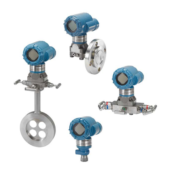
- Page 1 Quick Start Guide 00825-0100-4100, Rev CD June 2017 ™ Rosemount 3051 Pressure Transmitter and Rosemount 3051CF DP Flowmeters ® with WirelessHART Protocol...
-
Page 2: Table Of Contents
June 2017 Quick Start Guide NOTICE This guide provides basic guidelines for Rosemount 3051 Wireless Transmitters. It does not provide instructions for configuration, diagnostics, maintenance, service, troubleshooting or Intrinsically Safe (I.S.) installations. Refer to the Rosemount 3051 Wireless Reference Manual for more instruction. -
Page 3: Wireless Considerations
Gateway, beginning with the closest. This will result in a simpler and faster network installation. Enable Active Advertising on the Gateway to ensure that new devices join the network faster. For more information, see the Emerson Smart Wireless Gateway Reference Manual. -
Page 4: Transmitter Installation
June 2017 Quick Start Guide Transmitter installation Mount the transmitter Liquid applications Coplanar In-line 1. Place taps to the side of the line. 2. Mount beside or below the taps. Flow 3. Mount the transmitter so that the drain/vent valves are oriented upward. - Page 5 Quick Start Guide June 2017 Figure 2. Panel and Pipe Mounting Pipe mount Panel mount Coplanar flange Traditional flange In-line...
- Page 6 Use only bolts ™ supplied with the transmitter or sold by Emerson as spare parts. Figure 3 illustrates common transmitter assemblies with the bolt length required for proper transmitter assembly.
- Page 7 Quick Start Guide June 2017 Table 1. Torque Values for the Coplanar Flange and Flange Adapter Bolts Bolt material Head markings Initial torque Final torque Carbon Steel (CS) 300 in-lb. 650 in-lb. Stainless Steel (SST) 150 in-lb. 300 in-lb. In-line gage transmitter orientation The low side pressure port (atmospheric reference) on the in-line gage transmitter is located in the neck of the transmitter, behind the housing.
-
Page 8: Consider Housing Rotation
June 2017 Quick Start Guide Note A weep hole has been designed into the transmitter for safety and leak detection. If fluid begins to leak from the weep hole, isolate the process pressure, disconnect the transmitter, and reseal until the leak is resolved. Consider housing rotation To improve visibility of optional LCD display: 1. -
Page 9: Trim The Transmitter
Quick Start Guide June 2017 Trim the transmitter Devices are calibrated by the factory. Once installed, it is recommended to perform a zero trim on gage and differential pressure transmitters to eliminate error due to mounting position or static pressure effects. A zero trim can be performed using either a Field Communicator or configuration buttons. -
Page 10: Verify Transmitter Configuration
June 2017 Quick Start Guide Note A zero trim can also be completed using AMS Wireless Configurator once the device has joined the network. Verify transmitter configuration Operation can be verified in four locations: At the device via the Local Display (LCD display). ... - Page 11 This page will show whether the device has joined the network and if it is communicating properly. Note It may take several minutes for the device to join the network. See the Emerson Smart Wireless Gateway Quick Start Guide...
- Page 12 June 2017 Quick Start Guide Figure 8. Gateway Network Settings Verifying configuration using AMS Wireless Configurator When the device has joined the network, it will appear in the AMS Wireless Configurator as shown in Figure Figure 9. Wireless Configurator Network Setup...
-
Page 13: Troubleshooting
Quick Start Guide June 2017 Troubleshooting If the device has not joined to the network after power up, verify the correct configuration of the network ID and join key. Verify that active advertising has been enabled on the Smart Wireless Gateway. The network ID and join key in the device must match the network ID and join key of the Gateway. -
Page 14: Product Certifications
RF spectrum. Nearly every country requires this type of product certification. Emerson is working with governmental agencies around the world to supply fully compliant products and remove the risk of violating country directives or laws governing wireless device usage. - Page 15 Quick Start Guide June 2017 Special Conditions for Safe Use (X): 1. The Rosemount 3051 Wireless Pressure Transmitter shall only be used with the ™ 701PGNKF Rosemount SmartPower Battery Pack. 2. The in-line pressure sensor may contain more than 10% aluminum and is considered a potential risk of ignition by impact or friction.
- Page 16 June 2017 Quick Start Guide Special Conditions for Safe Use (X): 1. The plastic enclosure may constitute a potential electrostatic ignition risk and must not be rubbed or cleaned with a dry cloth. 2. The Model 701PGNKF Power Module may be replaced in a hazardous area. The power module has a surface resistivity greater than 1 GΩ...
- Page 17 Quick Start Guide June 2017 Figure 10. Rosemount 3051 Wireless Declaration of Conformity EU Declaration of Conformity No: RMD 1087 Rev. F Rosemount, Inc. 8200 Market Boulevard Chanhassen, MN 55317-9685 declare under our sole responsibility that the product, Rosemount 2051/3051 Wireless Pressure Transmitters manufactured by, Rosemount, Inc.
- Page 18 June 2017 Quick Start Guide EU Declaration of Conformity No: RMD 1087 Rev. F EMC Directive (2014/30/EU) Harmonized Standards: EN 61326-1: 2013 EN 61326-2-3: 2013 Radio Equipment Directive (RED) (2014/53/EU) Harmonized Standards: EN 300 328 V2.1.1 EN 301 489-1 V2.2.0 EN 301 489-17 V3.2.0 EN 61010-1: 2010 EN 62479: 2010...
- Page 19 Quick Start Guide June 2017 EU Declaration of Conformity No: RMD 1087 Rev. F ATEX Directive (2014/34/EU) Baseefa12ATEX0228X – Intrinsic Safety Certificate Equipment Group II, Category I G Ex ia IIC T4 Ga Harmonized Standards: EN 60079-0:2012 + A11:2013 EN 60079-11:2012 PED Notified Body DNV GL AS [Notified Body Number: 0575] Veritasveien 1, N-1322...
- Page 20 June 2017 Quick Start Guide Rosemount 3051 China RoHS List of Rosemount 3051 Parts with China RoHS Concentration above MCVs / Hazardous Substances Hexavalent Polybrominated Polybrominated Part Name Lead Mercury Cadmium Chromium biphenyls diphenyl ethers (Pb) (Hg) (Cd) (Cr +6) (PBB) (PBDE) Electronics...
- Page 21 Quick Start Guide June 2017...
- Page 22 Standard Terms and Conditions of Sale can be found on the Terms Enquiries@AP.Emerson.com and Conditions of Sale page. The Emerson logo is a trademark and service mark of Emerson Middle East and Africa Regional Office Electric Co. Emerson Automation Solutions SmartPower, Rosemount and Rosemount logotype are trademarks Emerson FZE P.O.
- Page 23 Quick Start Guide June 2017...
Need help?
Do you have a question about the Rosemount 3051CF DP and is the answer not in the manual?
Questions and answers