Table of Contents
Advertisement
Instruction Manual
AC Servo Motor & Driver
MINAS E-series
Thank you very much for buying Panasonic AC Servo Motor & Driver, MINAS E-series.
Before using this driver, please read this manual especially refer the safty precautions (page 8 to 11) to ensure
proper use.
Then, keep this manual for your future use.
Buy: www.ValinOnline.com | Phone 844-385-3099 | Email: CustomerService@valin.com
Advertisement
Chapters
Table of Contents
Troubleshooting

Subscribe to Our Youtube Channel
Related Manuals for Panasonic Minas E Series


Summary of Contents for Panasonic Minas E Series
- Page 1 AC Servo Motor & Driver MINAS E-series Thank you very much for buying Panasonic AC Servo Motor & Driver, MINAS E-series. Before using this driver, please read this manual especially refer the safty precautions (page 8 to 11) to ensure proper use.
-
Page 2: Before Use
Contents [Before Use] Page Safety Precautions ....................8 Maintenance/Inspections ..................12 Introduction ......................14 General ..............................14 After Opening the Package ........................14 Model of Driver ............................14 Model of Motor ............................15 Check the Combination of Driver and Motor .................... 15 Parts Description .................... - Page 3 Parameter Setting Mode .......................... 57 Normal Auto Gain Tuning Mode....................... 58 Alarm Clear .............................. 59 Test Run (JOG) ............................60 Test Run Procedures ..........................61 Copy Function ............................62 [Connections and Settings in Position Control Mode] Page Control Block Diagram in Position Control Mode ..........66 Wiring to Connector CN X5 ................
- Page 4 Inspection prior to Test Run ........................110 Test Run with Connector CN X5 Connected..................111 Real time Auto Gain Tuning ................114 Outline ..............................114 Scope ..............................114 Operating Instruction ..........................114 Parameters to be Set Automatically....................... 115 Cautions ..............................115 Parameter Setting ....................
- Page 5 [Trouble Case] Page Protective Functions ..................144 What are Protective Functions? ......................144 Details of Protective Functions ......................145 Software limit function ..........................148 Troubleshooting ....................150 [Reference] Page Outline of “PANATERM ”, Setup Support Software ................156 ® Communications ............................ 158 Description on Dividing/Multiplier Ratio ....................
- Page 6 MEMO Buy: www.ValinOnline.com | Phone 844-385-3099 | Email: CustomerService@valin.com...
-
Page 7: Table Of Contents
Before Use Page Safety Precautions ............8 Maintenance/Inspections ..........12 Introduction ..............14 General ....................14 After Opening the Package ..............14 Model of Driver ..................14 Model of Motor ..................15 Check the Combination of Driver and Motor ........... 15 Parts Description ............ -
Page 8: Safety Precautions
Safety Precautions Important See the following precautions in order to avoid damages on machinery and injuries among the operators and other people during the operation. The following symbols are used to indicate the degrees of hazard seriousness possibly occurred when you fail to comply with the safety precautions. - Page 9 [Before Use] DANGER Do not place inflammable matter Do not install the console near near the motor, driver, and sources of heat like the heater, the regenerative resistor. resistor, or etc. The failure could result in The failure could result in fire or damages.
- Page 10 Safety Precautions Important CAUTION Do not hold the cables or motor Do not block the heat dissipation shaft when transporting the motor. hole. The failure could result in The failure could result in injuries. electric shocks, or fire. Never start and stop the motor by Do not climb or stand on the servo magnet contactor which is provide on equipment.
- Page 11 [Before Use] CAUTION Use the motor and driver with the Make sure that the wirings are specified combination. correctly connected. The failure could result in The failure could result in electric shocks, or injuries. fire. Use the eye-bolt of the motor only Install the driver and the motor in the when you carry the motor.
-
Page 12: Maintenance/Inspections
Maintenance/Inspection • Routine maintenance and inspections are essential for proper and satisfactory operation of the driver and motor. Notes to Maintenance/Inspections Personnel (1) Power-on/off operations should be done by the operators themselves. (2) For a while after power off, the internal circuits is kept charged at higher voltage. Inspections should be done a while (about 10 minutes), after the power is turned off and the LED lamp on the panel is extinguished. - Page 13 [Before Use] Replacement Guidance Parts replacement cycles depend on the actual operating conditions and how the equipment has been used. Defective parts should be replaced or repaired immediately. Dismantling for inspections or repairs should be done by our company (or our sales agents). Prohibited Standard replacement Equipment...
-
Page 14: Introduction
Introduction General MINAS-E series is a unit of an AC servo motor and driver with downsized capability and performance that are useful for positioning of a motor whose capacity is small from 50W to 400W. By adopting 2500 P/r incremental encoder with velocity response frequency of approximately 400 Hz and 5 wires, we could omit wiring. -
Page 15: Model Of Motor
[Before Use] Model of Motor Name plate CONT. TORQUE 0.64 AC SERVO MOTOR RATING MODEL No. MUMA022PIS INS. CLASS B (T V) A (UL) Type Serial Number INPUT 3flAC IP65 CONNECTION Rated output Ex.:03010001 RATED OUTPUT SER No. 03010001 RATED FREQ. Rated speed RATED REV. -
Page 16: Parts Description
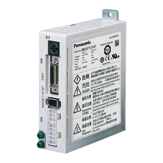
Parts Description Driver Status LED Alarm Code LED STATUS ALM CODE Connector for Serial Communications (X6) Interface Connector (X5) Encoder Connector (X4) Motor Connector (X3) Main Power Supply Connector (X1) Motor MUMA 50W - 400W Encoder Cable Encoder Motor Cable Frame Flange Mounting Holes (in 4 locations) -
Page 17: Console
[Before Use] Console Main body Connector Console main unit Display (7-segment LED) Cable Touch panel <Remarks> The console is optionally available. (Part No.: DV0P3690) Touch panel Display, LED (display in 6 digits) Display of selected Driver ID No. (2 digits) The value set up on Pr00 (shaft name) is ID No. -
Page 18: Installation
Installation The driver and motor should be properly installed to avoid failures, mechanical damages and injuries. Driver Location (1) Indoors, where the driver is not subjected to rain water and direct sun beams. Note that the driver is not a waterproof structure. - Page 19 [Before Use] Driver mounted to DIN rail Part where DIN rail is mounted Press lightly. With rail stop Ensure that the rail stop pushed in has been pushed in. DIN rail Press lightly the lower part of Hook the upper side of DIN rail mounting part on the DIN rail.
-
Page 20: Motor
Installation Motor Location (1) Indoors, where the driver is not subjected to rain water and direct sun beams. (2) The place where the motor is not exposed to corrosive atmospheres such as hydrogen sulfide, sulfurous acid, chlorine, ammonia, sulfur, chlorine gas, sulfuric gas, acid, alkali, salt, etc. and is free from splash of flammable gas, grinding coolant, oil mist, iron powder, chips, etc. - Page 21 [Before Use] Cable: Stress relieving (1) Don’t apply stress to the cable lead-out port and connections by bending and self-weight. (2) Particularly in the case of application in which the servo motor must be movable, fix the accessory cable of the motor and house the extension junction cable, which is connected to the terminal end of the said cable, in the cable bearer to thereby minimize stress acting on the cable by bending.
-
Page 22: Console
Installation Console Location (1) Indoors, where the driver is not subjected to rain water and direct sun beams. The console is not water- resistant. (2) The place where the driver is not exposed to corrosive atmospheres such as hydrogen sulfide, sulfurous acid, chlorine, ammonia, sulfur, chlorine gas, sulfuric gas, acid, alkali, salt, etc. - Page 23 Preparations Page System Configuration and Wiring ....... 24 General Wiring Diagram ................. 24 List of Driver and Compatible Peripheral Equipment ......26 Wiring of Connectors CN X1 and X3 (Wiring of Main Circuits) ....27 Wiring of Connector CN X4 (Connection with Encoder) ......29 Wiring of Connector CN X5 (Connection with Host Controller) ....
-
Page 24: System Configuration And Wiring
System Configuration and Wiring General Wiring Diagram Main Circuits (Refer to Page 26) Circuit Breaker (NFB) Used to protect the power lines: overcurrent will shut off the circuit. (Refer to Page 26, 182) Noise Filter (NF) Prevents the external noise from the power line, and reduces the effect of the noises generated by the servo motor. - Page 25 [Preparations] Personal computer Setup support software "PANATERM " Console STATUS ALM CODE Wiring to Connector CN X6 (Connection with personal computers and consoles) Wiring to Connector CN X5 (Connection with host controllers such as PLC, etc.) Wiring to Connector CN X4 (Connection with encoder) Junction cable for encoder pply)
-
Page 26: List Of Driver And Compatible Peripheral Equipment
System Configuration and Wiring List of Driver and Compatible Peripheral Equipment Cable Driver Magnetic contactor Required diameter Circuit breaker (composition of Noise filter Power Power (L1, L2, L3, Series Output (rated current) contacts) voltage (rated load) U, V, W, E) 0.3kVA BBC25N MKDE... -
Page 27: Wiring Of Connectors Cn X1 And X3 (Wiring Of Main Circuits)
[Preparations] Wiring of Connectors CNX1, X3 (Wiring of Main Circuits) • Don’t fail to request an electric wiring specialist for wiring. • Don’t switch ON the electric power until completion of the wiring, to prevent electric shock. Points in Wiring (1) For the cable diameter used, refer to “List of Driver and Compatible Peripheral Equipment”... - Page 28 System Configuration and Wiring Wiring Diagrams Compose such a power supply as to switch OFF the power against alarm output. For three-phase 200V Power supply Noise filter 172167-1 172159-1 (Tyco Electronics (Tyco Electronics 5557-10R-210 AMP K.K.) AMP K.K.) CN X1 (Molex Incorporated) White or yellow...
-
Page 29: Wiring Of Connector Cn X4 (Connection With Encoder)
[Preparations] Wiring to Connector CN X4 (Connection with Encoder) Points in Wiring Cable length between the driver and the motor - 20 m max. Encoder If this cable length exceeds 20 m, consult with the STATUS ALM CODE dealer/distributor from which you have purchased the 20 m max. -
Page 30: Wiring Of Connector Cn X5 (Connection With Host Controller)
System Configuration and Wiring Wiring of Connector CN X5 (Connection with Host Controller) Points in Wiring Within 3 m Place any peripheral equipment such as a host controller within 3 meters from the driver. STATUS ALM CODE Controller Separate the wiring at least 30 cm or more from the main circuit wires. 30 cm or More The wiring should neither run through a same duct as the main circuit Power... -
Page 31: Wiring Of Connector Cn X6 (Connection With Personal Computer/Console)
[Preparations] Wiring of Connector CN X6 (Connection with Personal Computer/Console) • It is capable of RS232C communications. For RS232C communications only 1) Connect the personal computer and driver 1:1 through RS-232C, and use “PANATERM ” (optional component), ® the setup supporting software. Running “PANATERM ”... -
Page 32: Timing Chart
Timing Chart After Power-ON (Receiving Servo-ON Signal) Power Supply Approx. Established Internal Control 700 ms Power Supply Initialize Approx. 2 seconds Normal Operation Initialization of Driver Servo-ON Input (SRV-ON) (X5 2 pins) Approx. 2 seconds Approx. 1 - 5 ms Dynamic Brake Approx. - Page 33 [Preparations] After an Alarm event (during Servo-ON) Normal Error Alarm Operation *2 Dynamic Brake 1 - 5 ms Motor Energized Energized Not Energized Servo Alarm Not Alarm Alarm (ALM) Setting of Pr6B Release (ON) Brake Release Operation (OFF) (BRK-OFF) t1 *1 Approx.
- Page 34 Timing Chart Servo-ON/OFF Operation When the Motor is Stopped (During normal operation, perform the Servo-ON/OFF operation after the motor stops.) Servo-ON Input (SRV-ON) Approx. 1 - 5 ms Approx. 1 - 5 ms Dynamic Brake Release Operation *3 Operation *2 t1 *1 Motor Energized Not Energized...
-
Page 35: Holding Brake
Holding Brake [Preparations] The brake is to hold a work (movable part) and prevent it from dropping by gravity when power to the servo is shut off for the purpose of driving a vertical shaft in the servo motor. <Caution> The brake built in the servo motor is only for holding, namely, maintaining, stopped condition. -
Page 36: Dynamic Brake (Db)
Dynamic Brake Dynamic Brake Dynamic brake is built in this driver for emergency stop. For this dynamic brake observe the precautions given below. <Notes> 1. This dynamic brake functions for emergency stop of the driver. Don’t start and stop by ON/OFF of the Servo-ON signal (SRV-ON signal). Doing so could result in rupture of the dynamic brake circuit built in the driver. - Page 37 [Preparations] (1) Setting driving conditions through deceleration and stop by turning on Servo-OFF (Pr69) Sequence at Driving Conditions Status of During Servo-OFF (Pr69) After stop Deviation Counter deceleration Setting of Pr69 Cleared Free Run Cleared Free Run Cleared Free Run Free Run Cleared Holding...
-
Page 38: Homing Operation (Precautions)
Homing Operation (Precautions) In initialization (i.e., operation to return to a home position) by using the host controller, if origin input (Z-phase from the encoder) is entered before the motor has not adequately decelerated since the proximity sensor was activated, the motor may not stop at a requested position. In order to prevent this, determine positions where the proximity input and origin input turn on, by taking into consideration the number of pulses required for successful deceleration. -
Page 39: Setting The Parameters
Setting the Parameters [Preparations] Overview of Parameters The servo driver has various parameters to set up its characteristics, functions, etc. This Section describes the function and purpose of each parameter. Before using, understand well the descriptive contents and adjust each parameter to the condition optimum to your intended operational conditions. -
Page 40: How To Connect
Setting the Parameters How to Connect RS-232C connecting cable • DV0P1960 (for DOS/V) STATUS ALM CODE Connecting to CNX6 Setup Disk for Setting-up Support Console Software “PANATERM ” • DV0P3690 ® • DV0P4230: Japanese version • DV0P4240: English version For the latest version, contact us. Connecting to CNX6 <Notes>... -
Page 41: Parameter Groups And Listing
[Preparations] Parameter Groups and Listing Parameter No. Group Briefing These parameters are used to select control mode, allocate I/O Function selecting 00 - 0E signals and to set up communication baud rate. These parameters are used to set up servo gains (1st, 2nd) of 10 - 1E position, velocity, integration, etc. - Page 42 Setting the Parameters Parameters for Selecting Function Parameter No. Parameter description Range Default Unit Related control mode Axis address 1 - 15 — P • P2 • S 7-segment LED for console, initial condition display 0 - 15 — P • P2 • S P •...
- Page 43 [Preparations] Parameters for Adjustment for 2nd Gain P: High velocity response positioning control, P2: High function positioning control, S: Internal velocity control Parameter No. Parameter description Range Default Unit Related control mode 2nd gain action set-up 0 - 1 <1> —...
- Page 44 Setting the Parameters Parameters for Positioning Control P: High velocity response positioning control, P2: High function positioning control, S: Internal velocity control Parameter No. Parameter description Range Default Unit Related control mode Command pulse multiplier set-up 1 - 4 — P •...
- Page 45 [Preparations] Pr5E 1st Torque Limit Set-up Driver Parameter 5E standard Motor model power default setup value MUMA5AZP1 1-phase MUMA011P1 100V MUMA021P1 MUMA5AZP1 1-phase/ MUMA012P1 3-phase MUMA022P1 200V MUMA042P1 • Pr5E 1st torque limit can’t be set up in excess to the value that was set up before shipping, under “Maximum Torque Setting”...
- Page 46 Setting the Parameters Parameters for Sequence P: High velocity response positioning control, P2: High function positioning control, S: Internal velocity control Parameter No. Parameter description Range Default Unit Related control mode In-position range 0 - 32767 Pulse P • P2 Zero speed 0 - 20000 r/min...
-
Page 47: Using The Console
Using the Console [Preparations] Using the Console Display, LED (display in 6 digits) Display of selected Driver ID No. (2 digits) The value set up on Pr00 (shaft name) is ID No. Parameter No. (2 digits) is displayed under “Parameter Setting” mode. MINAS DIGITAL AC SERVO This is used to shift the digits of data to be changed. -
Page 48: Structure Of Each Mode
Using the Console Structure of Each Mode The structure of each mode and the mode switching procedure can be changed with each button on the operation panel. Selection Display Set button Initial state of console LED Mode switch MODE button Mode switch MODE button... - Page 49 [Preparations] Execution Display ------Page 50 Set button Set button ------Page 57 For details on parameters, refer to Position Control Mode on Page 65 and Internal Velocity Control Mode on Page 103. Set button ------Page 50 Set button ------Page 58 ------Page 59 Alarm clear Set button Unusable...
- Page 50 Using the Console Example of Settings Insert the connector of console into CN X6 of the driver, and then turn on the power of the driver. Setting parameters: Press Press MODE Select the parameter to be set with MINAS Press DIGITAL AC SERVO Change the value with SHIFT...
-
Page 51: Monitoring Mode
[Preparations] Monitoring Mode When power of the servo driver is turned on for the first time after the driver is purchased, appears on the display (when the motor is stopped). If the indication on the display that appears after turning on power is to be changed, change the initial setting of Pr01LED. - Page 52 Using the Console Display of positional deviation, rotation speed of motor, and torque output Data •••••• Positional deviation (cumulative number of pulses counted by deviation counter) • Indication with "-" : Rotation torque is generated in CW direction viewed from the end of axis. Without "-"...
- Page 53 [Preparations] Display of input/output signal status The status of control input/output signal connected with connector CN X5 is displayed. Make use of this display to check the quality of wiring and for other purposes. Select no. of the signal to be monitored by pressing (No.
- Page 54 Using the Console Correspondence between signal no., signal name, and signal status Input signals Connector CN X5 Description Signal no. Signal name Designation Pin no. Servo-ON SRV-ON When Servo-ON signal is connected (turned on), A is indicated. Alarm clear A-CLR When alarm clear signal is connected (turned on), A is indicated.
- Page 55 [Preparations] Referring to error factors and error history It is possible to review the factors of the past 14 errors including current error. Select the error to be reviewed by pressing <Note> Error code No. The following errors are not recorded in the error history: ("...
- Page 56 Using the Console Warning display No occurrence of warning Occurrence of warning Warning of overload: Load has exceeded 85% of the level where overload protection alarm occurs. Warning of regenerative overload: Regenerative load has exceeded 85% of the level where regenerative overload protection alarm occurs.
-
Page 57: Parameter Setting Mode
[Preparations] Parameter Setting Mode Operations with Selection Display Bring in the display of by pressing once after pressing in the initial parameter setting mode MOOD state of LED. Parameter No. (hexadecimal) <Note> The parameters in which “r” is indicated in this place are made active after they are changed and written into EEPROM and then power is once turned off. -
Page 58: Normal Auto Gain Tuning Mode
Using the Console Normal Auto Gain Tuning Mode <Notes> • For details on normal auto gain tuning function, refer to “Normal Auto Gain Tuning” on Page 132 of Adjustment edition. Especially, please thoroughly understand the scope and cautions described in the manual to use the auto gain tuning function. -
Page 59: Alarm Clear
[Preparations] Alarm Clear The motor stop condition (trip condition) is cleared by the protective function. Operations with Selection Display Enter the auxiliary function mode by pressing once and four times in MODE by pressing the initial state of LED, and then bring in Operation with Execution Display by pressing Reveal execution display... -
Page 60: Test Run (Jog)
Using the Console Test Run (JOG) It is possible to make test runs without connecting any host controller such as PLC to connector CN X5. <Note> • Be sure to make test runs after isolating the motor from the load and disconnecting connector CN X5. •... -
Page 61: Test Run Procedures
[Preparations] Test Run Procedure Turn on power for the driver and connect the console connector to connector CN X6 of the driver. Display of motor rotation speed (Initial state of LED) Operations with Selection Display Enter the auxiliary function mode by pressing once and four times, and then bring in by pressing... -
Page 62: Copy Function
Using the Console Copying parameters from servo driver to console (Copy Function) Operations with Selection Display Enter the copy mode by pressing once and MODE five times in the initial state of LED, and then bring in by pressing Operation with Execution Display Reveal execution display by pressing Keep pressing... - Page 63 [Preparations] Copying parameters from console to servo driver (Copy Function) Operations with Selection Display Enter the copy mode by pressing once and five MODE times in the initial state of LED, by pressing and then bring in Operation with Execution Display Reveal execution display by pressing Keep pressing...
- Page 64 MEMO Buy: www.ValinOnline.com | Phone 844-385-3099 | Email: CustomerService@valin.com...
- Page 65 Connections and Settings in Position Control Mode Page Control Block Diagram in Position Control Mode ..66 Wiring to Connector CN X5 .......... 67 Example of Wiring in Position Control Mode ........... 67 Interface Circuit ..................68 Input Signal and Pin No. of Connector CN X5 ........70 Output Signal and Pin No.
-
Page 66: Control Block Diagram In Position Control Mode
Control Block Diagram in Position Control Mode When Pr02, parameter for setting control mode is [0] or [2]*: Buy: www.ValinOnline.com | Phone 844-385-3099 | Email: CustomerService@valin.com... -
Page 67: Wiring To Connector Cn X5
Wiring to Connector CN X5 [Connections and Settings in Position Control Mode] Example of Wiring in Position Control Mode Example of Wiring in Position Control Mode Buy: www.ValinOnline.com | Phone 844-385-3099 | Email: CustomerService@valin.com... -
Page 68: Interface Circuit
Wiring to Connector CN X5 Interface Circuit Input Circuit Connection with Sequence Input Signal 12~24V 1 COM+4.7kΩ • Connect to a contact of switch and relay, or a transistor of an SRV-ON, etc. Relay open collector output. • When you plan to use a contact input, use switch and relay 12~24V for minute electric current so as to avoid poor contact. - Page 69 [Connections and Settings in Position Control Mode] Output Circuit Sequence Output Circuit Be sure to install in the direction shown in the figure. • This output circuit is configured with a Darlington connection ALM, etc. transistor output of open collector. It is connected to a relay or photo coupler.
-
Page 70: Input Signal And Pin No. Of Connector Cn X5
Wiring to Connector CN X5 Input Signal and Pin No. of Connector CN X5 Input signals (common) and their functions I/F Circuit Signal Name Pin No. Symbol Function Control Signal Power COM + • Connect positive (+) pole of external DC power supply (12 to —... - Page 71 [Connections and Settings in Position Control Mode] Pin No. Symbol Function I/F Circuit Signal Name Command Dividing The control mode can change functions. Multiplier Switching/ /INTSPD1 Page 68 Position • Input to switch dividing multiply of command Internal Command Control pulse Speed Selection 1 In- •...
-
Page 72: Output Signal And Pin No. Of Connector Cn X5
Wiring to Connector CN X5 Output Signal and Pin No. of Connector CN X5 Output Signals (Common) and their Functions Signal Name Pin No. Symbol Function I/F Circuit Servo Alarm Output • The output transistor turns OFF when an alarm is generated. Page 69 Positioning Comple- COIN... -
Page 73: Example Of Connection To A Host Controller
[Connections and Settings in Position Control Mode] Example of Connection to a Host Controller Matsushita Electric Works, Ltd. FPG-C32T Driver FPG-C32T (Matsushita Electric Works, Ltd. FP∑) E-series 2kΩ PULS1 CW pulse CW pulse command command 220Ω output PULS2 input 2kΩ SIGN1 CCW pulse CCW pulse command... - Page 74 Wiring to Connector CN X5 Matsushita Electric Works, Ltd. FP2-PP22 AFP2434/FP2-PP42 AFP2435 Driver FP2-PP22 AFP2434(Matsushita Electric Works, Ltd.) E-series FP2-PP42 AFP2435(Matsushita Electric Works, Ltd.) PULS1 (A10) CW pulse Pulse output A command 220Ω PULS2 input (B10) SIGN1 (A11) CCW pulse Pulse output B command 220Ω...
- Page 75 [Connections and Settings in Position Control Mode] Matsushita Electric Works, Ltd. FP2-PP2 AFP2430 Driver FP2-PP2 AFP2430(Matsushita Electric Works, Ltd.) E-series PULS1 CW pulse CW pulse command command 220Ω output PULS2 input SIGN1 CCW pulse CCW pulse command command 220Ω output SIGN2 input Phase Z...
- Page 76 Wiring to Connector CN X5 Yokogawa Electric Corporation F3NC11-ON Driver F3NC11-ON (Yokogawa Electric Corporation) E-series PULS1 CW pulse CW pulse command command 220Ω output PULS2 input SIGN1 CCW pulse CCW pulse command command 220Ω output SIGN2 input 1kΩ Origin line driver Phase Z input output...
- Page 77 [Connections and Settings in Position Control Mode] Yokogawa Electric Corporation F3YP14-ON/F3YP18-ON Driver F3YP14-ON/F3YP18-ON(Yokogawa Electric Corporation) E-series PULS1 CW pulse CW pulse command command 220Ω output PULS2 input SIGN1 CCW pulse CCW pulse command command output 220Ω SIGN2 input 240Ω Origin line driver Phase Z input output...
- Page 78 Wiring to Connector CN X5 Omron Corporation CS1W-NC113 (Open Collector Output) Driver CS1W-NC113(Omron Corporation) E-series 1.6kΩ PULS1 CW pulse CW pulse command command 220Ω output PULS2 input 1.6kΩ SIGN1 CCW pulse command CCW pulse output command 220Ω SIGN2 input 150Ω Origin line driver input Phase Z output...
- Page 79 [Connections and Settings in Position Control Mode] Omron Corporation CS1W-NC133 (Line Driver Output) Driver CS1W-NC133(Omron Corporation) E-series PULS1 CW pulse CW pulse command 220Ω command output PULS2 input SIGN1 CCW pulse CCW pulse command output 220Ω command SIGN2 input 150Ω Origin line driver Phase Z input...
- Page 80 Wiring to Connector CN X5 Omron Corporation C200H-NC211 Driver C200H-NC211(Omron Corporation) E-series 1.6kΩ PULS1 CW pulse Pulse (CW+CCW) 220Ω command output PULS2 input 1.6kΩ SIGN1 CCW pulse Direction output 220Ω command SIGN2 input 150Ω Origin line driver Phase Z input OZ–...
- Page 81 [Connections and Settings in Position Control Mode] Mitsubishi Electric Corporation A1SD75/AD75P1 <Note> You can switch output of an open collector/line driver. Use this with the line driver. If you use the open collector, it does not count pulse and the motor does not rotate. Driver A1SD75/AD75P1 (Mitsubish Electric Corporation) E-series...
-
Page 82: Test Run In Position Control Mode
Test Run in Position Control Mode Inspection prior to Test Run (1) Check the wirings: • Connected correctly (especially power supply connection and motor connection), • Not shorted and properly earthed, and Power STATUS ALM CODE • Not loose. supply (2) Check the supply Host Controller voltage:... - Page 83 [Connections and Settings in Position Control Mode] Parameters Input Signal Status Signal No. Input Signal Name Monitor Display PrNo. Parameter Name Settings Servo-ON Pr02 Control mode set up CW overtravel inhibit – Pr04 Overtravel input inhibit Pr42 Command pmulse input mode set up CCW overtravel inhibit –...
- Page 84 Test Run in Position Control Mode Basic Operations and LED Display (1) Turn on the power. Power STATUS ALM CODE Supply CN X4 Ground Machine Motor Buy: www.ValinOnline.com | Phone 844-385-3099 | Email: CustomerService@valin.com...
- Page 85 [Connections and Settings in Position Control Mode] (2) Check LED status. Color of Description LED Status Green The main power is turned ON. The driver is switched ON. The LED flashes (for 1 second) when a warning is issued. Orange (Abnormal overload, regeneration, and fan rotation speed) Alarm output.
-
Page 86: Real Time Auto Gain Tuning
Real time Auto Gain Tuning Automatic Automatic Outline Position/velocity gain setting filter tuning Torque Motor command command current Position/velocity Adaptive Current Motor control command filter Operation command under Load inertia of the machine is real-time estimated, and actual service conditions Estimation of based on the result of estimation, optimum gain is resonance frequency... -
Page 87: Adaptive Filter
[Connections and Settings in Position Control Mode] Adaptive Filter An adaptive filter will be enabled when Pr02=2 (high function positioning control mode) and Pr21 (Real time auto tuning set-up) is 1 to 3 or 7. The adaptive filter reduces resonance point vibration, by estimating resonance frequency from vibration component that appears in motor speed in operation, and removing resonance component from a torque command through automatic setting of a coefficient of a notch filter. -
Page 88: Parameter Setting
Parameter Setting Parameter for Selection of Functions Standard Default Setup: [ ] Range of PrNo. Parameter Name Function/Content Settings Axis address 0 - 15 In communications with a host such as a personal computer that uses RS232C with multiple axes, you should identify to which axis the host is accessing. With this parameter, you can see an axis name by number. - Page 89 [Connections and Settings in Position Control Mode] Standard Default Setup: [ ] Range of PrNo. Parameter Name Function/Content Settings Overtravel Input in- 0 - 1 In the case of linear driving, in particular, limit switches should be provided on both hibit ends of the axis, as illustrated in the figure below, to prevent any mechanical dam- age due to overshoot of a work, and inhibit driving in the direction in which the...
- Page 90 Parameter Setting Standard Default Setup: [ ] Range of PrNo. Parameter Name Function/Content Settings Baud rate set-up of 0 - 2 Settings Baud Rate RS232C 2400bps 4800bps 9600bps Buy: www.ValinOnline.com | Phone 844-385-3099 | Email: CustomerService@valin.com...
-
Page 91: Parameters For Adjustment Of Time Constants Of Gains/Filters
[Connections and Settings in Position Control Mode] Parameters for Adjustment of Time Constants of Gains/Filters Range of PrNo. Parameter Name Unit Function/Content Settings 1st position loop 0 - 32767 • The parameter determines responsiveness of the position control [63] * gain system. -
Page 92: Parameters For Auto Gain Tuning
Parameter Setting Parameters for Auto Gain Tuning Standard Default Setup: [ ] Range of PrNo. Parameter Name Unit Function/Content Settings Inertia ratio 0 - 10000 • The parameter sets a ratio of load inertia to rotor inertia of the motor. [100]* Pr20 = (Load inertia/rotor inertia) x 100 [%] •... - Page 93 [Connections and Settings in Position Control Mode] Range of PrNo. Parameter Name Unit Function/Content Settings Normal auto tuning 0 - 7 – • The parameter sets operation patterns of normal auto gain tuning. motion set-up Settings Number of Rotations Rotation Direction CCW →CW CW →CCW 2 rotations...
-
Page 94: Parameters For Adjustment (Related To Second Gain Switching Function)
Parameter Setting Parameters for Adjustment (Related to Second Gain Switching Function) Standard Default Setup: [ ] Range of PrNo. Parameter Name Unit Function/Content Settings 2nd gain action 0 - 1 – • Set the parameter when you carry out optimum tuning by using gain set-up switching function. -
Page 95: Parameters For Position Control
[Connections and Settings in Position Control Mode] Range of PrNo. Parameter Name Unit Function/Content Settings Position loop gain 0 - 10000 (Setting value+1) • With the 2nd gain switching function enabled, you can provide switching time [20]* x 166 ms phased switching time only for position loop gain when gain is switched. - Page 96 Parameter Setting Range of PrNo. Parameter Name Function/Content Settings Command pulse 0 - 3 (Cont’d) input mode set-up Allowable input maximum frequency of command pulse input signal and minimum required time width (Cont’d) Minimum required time width[µ µ µ µ µ s] Input I/F of PULS/ Allowable input SIGN signal...
- Page 97 [Connections and Settings in Position Control Mode] Standard Default Setup: [ ] Range of PrNo. Parameter Name Function/Content Settings Related to command pulse dividing multiplier function (Pr46, 47, 4A, 4B) Numerator of 1st Command pulse dividing multiplier (electronic gear) function 10000 •...
-
Page 98: Parameters For Internal Velocity Control
Parameter Setting Standard Default Setup: [ ] Range of PrNo. Parameter Name Function/Content Settings Smoothing filter 0 - 7 A smoothing filter is the primary delay filter inserted after command dividing set-up multiply part of the command pulse input part. Purpose of smoothing filter •... -
Page 99: Parameters For Torque Limits
[Connections and Settings in Position Control Mode] Parameters for Torque Limits Range of PrNo. Parameter Name Function/Content Settings 1st torque limit set- • With this parameter set, maximum torque of the motor is limited in the driver. • Normal specification allows torque about 3 times as large as rated torque, if in an instant. - Page 100 Parameter Setting Standard Default Setup: [ ] Range of PrNo. Parameter Name Function/Content Settings Zero speed • The parameter directly sets in [r/min] timing to output zero speed detection 20000 output signal (WARN: CN X5 pin 12). [50] You need to set parameter warning output selection (Pr09) to 1. •...
- Page 101 [Connections and Settings in Position Control Mode] Standard Default Setup: [ ] Range of PrNo. Parameter Name Function/Content Settings Sequence at alarm 0 - 3 The parameter sets driving conditions during deceleration after alarm is generated as a result of activation of any of protective functions of the driver, or after the motor stops.
- Page 102 Parameter Setting Standard Default Setup: [ ] Range of PrNo. Parameter Name Function/Content Settings Mech. break action Unlike Pr6A, Pr6B sets time from when the motor is de-energized (servo free) until set-up at motor in the brake release signal (BRK-OFF:CN X5 pin 11) turns off (i.e., brake retained), motion when Servo-OFF is activated while the motor is still rotating.
- Page 103 [Connections and Settings in Position Control Mode] Connections and Settings in Internal Velocity Control Mode Page Control Block Diagram in Internal Velocity Control Mode 104 Wiring to Connector CN X5 ........105 Example of Wiring to Connector CN X5 ..........105 Interface Circuit ..................106 Input Signal and Pin No.
-
Page 104: Control Block Diagram In Internal Velocity Control Mode
Control Block Diagram in Internal Velocity Control Mode When Pr02, parameter for setting internal control mode is [1]: Buy: www.ValinOnline.com | Phone 844-385-3099 | Email: CustomerService@valin.com... -
Page 105: Wiring To Connector Cn X5
Wiring to Connector CN X5 [Connections and Settings in Internal Velocity Control Mode] Example of Wiring to Connector CN X5 Example of Wiring in Internal Velocity Control Mode Buy: www.ValinOnline.com | Phone 844-385-3099 | Email: CustomerService@valin.com... -
Page 106: Interface Circuit
Wiring to Connector CN X5 Interface Circuit Input Circuit Connection with Sequence Input Signal 12~24V 1 COM+4.7kΩ • Connect to a contact of switch and relay, or a transistor of an SRV-ON, etc. Relay open collector output. • When you plan to use a contact input, use switch and relay 12~24V for minute electric current so as to avoid poor contact. -
Page 107: Input Signal And Pin No. Of Connector Cn X5
[Connections and Settings in Internal Velocity Control Mode] Input Signal and Pin No. of Connector CN X5 Input signals (common) and their functions Signal Name Pin No. Symbol Function I/F Circuit Control Signal Power COM+ • Connect positive (+) pole of external DC power supply (12 to ——... - Page 108 Wiring to Connector CN X5 Signal Name Pin No. Symbol Function I/F Circuit Gain Switching/ GAIN • Settings of Pr06 and control mode can change functions. Speed Zero Clamp/ /ZEROSPD Page 106 Torque Limit Switching Input Pr06 Control Mode Content The following 2 functions can be used with settings of Pr30.
-
Page 109: Output Signal And Pin No. Of Connector Cn X5
[Connections and Settings in Internal Velocity Control Mode] Output Signal and Pin No. of Connector CN X5 Output Signals (Common) and their Functions Signal Name Pin No. Symbol Function I/F Circuit Servo Alarm Output • The output transistor turns OFF when an alarm is generated. Page 106 Positioning COIN... -
Page 110: Test Run In Internal Velocity Control Mode
Test Run in Internal Velocity Control Mode Inspection prior to Test Run (1) Check the wirings: • Connected correctly (especially power supply connection and motor connection), • Not shorted and properly earthed, and • Not loose. (2) Check the supply voltage: •... -
Page 111: Test Run With Connector Cn X5 Connected
[Connections and Settings in Internal Velocity Control Mode] Test Run with Connector CN X5 Connected (1) Connect CN X5. (2) Connect the control signal (COM+/COM-) to the power supply (12 to 24 VDC). (3) Turn on the power (of the driver). (4) Change the control mode to internal velocity control mode (Pr02=1). - Page 112 Test Run in Internal Velocity Control Mode Basic Operations and LED Display (1) Turn on the power. Power STATUS ALM CODE Supply CN X4 Ground Machine Motor Buy: www.ValinOnline.com | Phone 844-385-3099 | Email: CustomerService@valin.com...
- Page 113 [Connections and Settings in Internal Velocity Control Mode] (2) Check LED status. Color of Description LED Status Green The main power is turned ON. The driver is switched on. The LED flashes (for 1 second) when a warning is issued. Orange (Abnormal overload, regeneration, and fan rotation speed) Alarm output.
-
Page 114: Real Time Auto Gain Tuning
Real time Auto Gain Tuning Automatic Automatic Outline Position/velocity gain setting filter tuning Torque Motor command command current Position/velocity Adaptive Current Motor control command filter Operation command under Load inertia of the machine is real time estimated, and actual service conditions Estimation of based on the result of estimation, optimum gain is resonance frequency... -
Page 115: Parameters To Be Set Automatically
[Connections and Settings in Internal Velocity Control Mode] Parameters to be Set Automatically The following parameters are tuned automatically. The following parameters are also set up to the following fixed values automatically. PrNo. Name PrNo. Name Setting 1st velocity loop gain 2nd gain action set-up 1st velocity loop integration time constant 1st speed detection filter... -
Page 116: Parameter Setting
Parameter Setting Parameter for Selection of Functions Standard Default Setup: [ ] Range of PrNo. Parameter Name Function/Content Settings Axis address 0 - 15 In communications with a host such as a personal computer that uses RS232C with multiple axes, you should identify to which axis the host is accessing. With this parameter, you can see an axis name by number. - Page 117 [Connections and Settings in Internal Velocity Control Mode] Range of PrNo. Parameter Name Function/Content Settings Control mode set 0 - 2 Setting Control Mode High velocity response positioning control (pulse row) Internal velocity control High function positioning control (pulse row) •...
- Page 118 Parameter Setting Standard Default Setup: [ ] Range of PrNo. Parameter Name Function/Content Settings Overtravel Input 0 - 1 In the case of linear driving, in particular, limit switches should be provided on inhibit both ends of the axis, as illustrated in the figure below, to prevent any mechanical damage due to overshoot of a work, and inhibit driving in the direction in which Work the switches operate.
-
Page 119: Parameters For Adjustment Of Time Constants Of Gains/Filters
[Connections and Settings in Internal Velocity Control Mode] Parameters for Adjustment of Time Constants of Gains/Filters Standard Default Setup: [ ] Range of PrNo. Parameter Name Unit Function/Content Settings 1st velocity loop 1 - 3500 • The parameter determines responsiveness of the velocity loop. To gain [35]* improve responsiveness of the entire servo system by setting the... -
Page 120: Parameters For Auto Gain Tuning
Parameter Setting Parameters for Auto Gain Tuning Standard Default Setup: [ ] Range of PrNo. Parameter Name Unit Function/Content Settings Inertia ratio 0 - 10000 • The parameter sets a ratio of load inertia to rotor inertia of the motor. [100]* Pr20 = (Load inertia/rotor inertia) x 100 [%] •... -
Page 121: Parameters For Position Control
[Connections and Settings in Internal Velocity Control Mode] Parameters for Position Control Standard Default Setup: [ ] Range of PrNo. Parameter Name Function/Content Settings Output pulses per 1 - 16384 The parameter sets the number of pulses per rotation of the encoder pulse to be single turn [2500] output to the host. -
Page 122: Parameters For Internal Velocity Control
Parameter Setting Parameters for Internal Velocity Control Standard Default Setup: [ ] Range of PrNo. Parameter Name Function/Content Settings 1st internal speed –20000 - These parameters directly set, in terms of [r/min], the first to fourth internal set-up 20000 command speed of when internal speed setting is enabled with the parameter “internal/external speed set-up switching”... -
Page 123: Parameters For Torque Limits
[Connections and Settings in Internal Velocity Control Mode] Parameters for Torque Limits Range of PrNo. Parameter Name Function/Content Settings • With this parameter set, maximum torque of the motor is limited in the driver. 1st torque limit set- • Normal specification allows torque about 3 times as large as rated torque, if in an instant. - Page 124 Parameter Setting Range of PrNo. Parameter Name Function/Content Settings Deceleration and 0 - 2 The parameter sets the deceleration and stop operation after the drive inhibit stop set-up at input (CCWL: Connector CNx58 pin or CWL: Connector CNx57 pin) activates and overtravel inhibit becomes enabled.
- Page 125 [Connections and Settings in Internal Velocity Control Mode] Standard Default Setup: [ ] Range of PrNo. Parameter Name Function/Content Settings Mech. break action The parameter enables you to set time from when the brake release signal (BRK- set-up at motor OFF:CN X5 pin 11) turns off until the motor becomes de-energized (servo free), standstill when you turn on Servo-OFF while the motor is stopped.
- Page 126 Parameter Setting Standard Default Setup: [ ] Range of PrNo. Parameter Name Function/Content Settings 1st over-speed 0 - 6000 Pr.06=2 The parameter sets a 1st overspeed level when torque limit switching input is level set-up enabled. If rotation speed of the motor exceeds this setting when the first torque limit is selected, overspeed error will be generated.
- Page 127 Adjustment Page Gain Adjustment............128 Objective of Gain Adjustment ..............128 Types of Gain Adjustment ..............128 Procedures of Gain Adjustment ............129 Real time Auto Gain Tuning ........130 Normal Auto Gain Tuning ........... 132 Cancellation of the Automatic Gain Tuning ....135 Manual Gain Tuning (Basic) ........
-
Page 128: Gain Adjustment
Gain Adjustment Objective of Gain Adjustment It is necessary that the motor runs with the least delay time and in response to a command from the driver. Hence, we need to adjust the gain of the motor to perform command, in order to maximize the performance of the machine. <Example: Ball Screw>... -
Page 129: Procedures Of Gain Adjustment
[Gain Adjustment] Procedures of Gain Adjustment The following flow chart illustrates the entire process of the gain adjustment: Start adjustment Do you select auto tuning? 13500 Can you enter Release the automatic P. 135 a command? adjustment function Release the automatic adjustment function (Default setup) P. -
Page 130: Real Time Auto Gain Tuning
Real time Auto Gain Tuning Automatic Automatic Outline Position/speed gain setting Torque filter tuning Motor command command current Current Position/velocity Adaptive Motor command control filter Operation command under Load inertia of the machine is real-time estimated, and the actual service conditions Estimation of optimum gain is automatically set based on the result of resonance frequency... - Page 131 [Gain Adjustment] Adaptive Filter Filters are effective when Pr02=2 (high-grade position control mode) and Pr21 is 1 to 3 or 7. The adaptive filter reduces the resonance point vibration, by estimating resonance frequency from the vibration component that appears at the motor operation, and removes the resonance component by torque command through automatic setting of a coefficient of a notch filter.
-
Page 132: Normal Auto Gain Tuning
Normal Auto Gain Tuning Outline Position command Motor acceleration Normal mode auto gain tuning In normal auto gain tuning, the motor runs at a command pattern Estimation of load inertia automatically generated by the driver, load inertia is estimated Automatic Motor gain tuning Torque based on the torque required then, and thus appropriate gain is... - Page 133 [Gain Adjustment] Operating Instructions (1) Set an operating pattern with Pr25. (2) Shift load to a position where there will be no problem if the motor executes the operating pattern set with Pr25. (3) Do not enter a command. (4) Activate Servo-ON. (5) Start auto gain tuning.
- Page 134 Normal Auto Gain Tuning How to Operate with Console (1) Switch from monitor mode to normal auto Motor rotation speed gain tuning mode, by pressing SET button indication (Initial display) and then mode switch button 3 times. For operating instructions, refer to Normal Auto Gain Tuning Mode on Page 58 of Preparation edition.
-
Page 135: Cancellation Of The Automatic Gain Tuning
Cancellation of the Automatic Gain Tuning [Gain Adjustment] Outline Cautions required when you disable the real time auto gain tuning which was unabled by default setup or an adaptive filter are stated. Cautions Cancel of the automatic adjustment function, at Servo-OFF. Disabling Real time Auto Tuning When you change Pr21 (real time auto tuning set-up) to 0 or 7 (only adaptive filter enabled), automatic estimation of Pr20 (inertia ratio) will stop and real time auto tuning will be disabled. -
Page 136: Manual Gain Tuning (Basic)
Manual Gain Tuning (Basic) Although MINAS-E series is equipped with the auto gain tuning function described above, you may have to readjust when you cannot successfully adjust gain even if you execute auto gain tuning, due to some constraint such as load conditions, etc., or when you wish to have the best responsiveness or stability appropriate to individual loads. - Page 137 [Gain Adjustment] Method of Adjustment in Position Control Mode (1) Set the following parameters to values listed in the table below: Parameter No. Parameter No. Target Target Parameter Name Parameter Name Value Value 1st position loop gain Inertia ratio 1st velocity loop gain Real time auto tuning set-up 1st velocity loop integration time constant Damping frequency...
-
Page 138: Manual Gain Tuning (Application)
Manual Gain Tuning (Application) Gain Switching Function In manual gain switching mode, you can Operation Command speed manually set a second gain in addition to a 1st Stopped Drive Stopped Time gain, and execute gain switching depending on State (servo lock) (servo lock) an operating state. - Page 139 [Gain Adjustment] *1 Delay time (Pr32) will be validated upon return from second gain to first gain. *2 Definition of hysteresis (Pr34) is as illustrated in the figure below: *3 If the condition that there is torque variation of 10% during 166 µs is included, setting should be 200.
-
Page 140: To Reduce Mechanical Resonance
Manual Gain Tuning (Application) To Reduce Mechanical Resonance When mechanical stiffness is low, vibration or noise is generated due to the torsion of shaft, and thus you may not be able to set the gain high. In such cases, you can suppress the resonance by using the following 2 types of filters. - Page 141 [Gain Adjustment] Examples of adaptive devices Gain Gain Gain Frequency Frequency Frequency Speed response Devices resonance points of which Devices having resonance peak in Devices having a resonance point vary depending on individual frequency spectrum remote from frequency of which does not change differences/aging speed response Possible to suppress a large...
-
Page 142: Anti-Vibration Control
Manual Gain Tuning (Application) Anti-Vibration Control Outline The leading end vibrates Vibration observed by a displacement sensor When the leading end of a device vibrates, the function removes vibration frequency component from a command Set vibration frequency at a leading end Driver Motor Movement... - Page 143 Trouble Case Page Troubleshooting ............144 What are Protective Functions? ............144 Details of Protective Functions .............145 Software limit function ................148 Protective Functions ........... 154 Buy: www.ValinOnline.com | Phone 844-385-3099 | Email: CustomerService@valin.com...
-
Page 144: Troubleshooting
Troubleshooting What are Protective Functions? The driver has various protective functions. If any of these functions activate, the motor stops immediately under trip condition, and simultaneously the “Servo Alarm Output” (ALM) will turn OFF (reset). Counteractions against motor trip • When the motor trips, status display LED (STATUS) on the upper part of the front panel of the servo driver turns red, and alarm code LED (ALM CODE) blinks. -
Page 145: Trouble Case
[Trouble Case] Details of Protective Functions Protective Alarm Cause Action Functions code No. Power During Servo-ON, voltage between P-N of the Measure the line voltage of the connector CN X1 voltage converter of the main power supply has dropped (L1, L2, L3). shortage below a specified value. - Page 146 Troubleshooting Alarm Protective Cause Action Functions code No. Overload When an integration value of a torque command On the waveform graphic screen of PANATERM ® Protection exceeds the set overload level, overload protection check if torque (current) waveform widely (OL) is activated based on time limiting characteristics.
- Page 147 [Trouble Case] Alarm Protective Cause Action code No. Functions *Encoder Ensure that the supply voltage of the encoder is Data from the encoder results in communication communi- DC5V±5% (4.75 to 5.25V). Be careful, in error, which is mainly caused by noise. Although cation data particular, when the encoder cable is long.
-
Page 148: Software Limit Function
Troubleshooting Protective Alarm Cause Action Functions code No. Missing phase Z pulse of 2500 [P/r] 5-serial The motor may have failed. Replace it. Then, *Encoder Z- encoder is detected. return it to the sales agent for inspection (repair). phase error The encoder is defective. - Page 149 [Trouble Case] (3) Notes • This function is not protection for abnormal position commands • When the software limit protection is activated, the motor will slow down and then stop in accordance with Pr68 (Sequence for alarm). • Some loads may collide with the with edges of the machine while the motor is slowing down. Set the Pr26 range allowing for this slow-down operation.
-
Page 150: Troubleshooting
Troubleshooting Checkpoints Ensure that status (STATUS) LED turns neither red nor orange. Ensure that the connector is firmly Ensure that LED is not blinking. fixed. STATUS ALM CODE Host Ensure that supply voltage hasn’t Controller changed. Ensure that correct voltage is supplied. Ensure that Make sure that wiring connections are... - Page 151 [Trouble Case] The rotation is not stable (the rotation is not smooth) Category Cause Action Adjustment Poor gain adjustment Increase the value of the 1st velocity loop gain Pr11. Insert a 1st torque filter Pr14 and increase the value of Pr11 again. Position command (pulse row Check how the motor is running, by using the waveform graphic command) is unstable.
- Page 152 Troubleshooting Positioning Accuracy is poor Category Cause Action System The position commands (amount of Count the number of feedback pulses either by repeatedly command pulse) are not correct. reciprocating for a fixed distance and using the monitoring function of PANATERM , or by using the monitor mode of ®...
- Page 153 [Trouble Case] Original position varies Category Cause Action System Phase Z is not detected when the Check if phase Z is superposed on proximity input (nearest original position is calculated. point dog sensor). Initialize correctly according to the controller. Speed to creep to the original position Decelerate the initialization speed in the vicinity of the original is fast.
-
Page 154: Protective Functions
Protective Functions Overshooting/Undershooting The motor is overheated (burnout) Category Cause Action Adjustment Gains are poorly adjusted. Check gains using the waveform graphic function of PANATERM . Correctly adjust gains. Refer to Section on ® Adjustment. Installation Load inertia is high. Check gains using the waveform graphic function of PANATERM . - Page 155 Reference Page Outline of “PANATERM ”, Setup Support Software ......156 ® Communications ...................158 Description on Dividing/Multiplier Ratio ..........178 Conformance to EC Directives/UL Standards ........180 Optional Parts ..................184 Recommended Parts ................192 Dimensional Outline Drawing ..............193 Allowable Load of Output Shaft ............196 Motor Characteristics (S-T Characteristics) ..........
-
Page 156: Outline Of "Panaterm ® ", Setup Support Software
Outline of “PANATERM ”, Setup Support Software ® Connection Method RS-232 Cable DV0P1960 (For DOS/V) STATUS ALM CODE Connecting to CN X6 Please contact us for the latest version of setup disk of “PANATERM ”, setup support software. ® • DV0P4230 (Japanese version) ®... - Page 157 [Reference] Starting PANATERM ® <Cautions/Remarks> 1. Once you have installed “PANATERM ” on the hard disk, you do not have to reinstall it every time you boot up. ® 2. Before you start, connect the driver with the power supply, motor, and encoder. For the startup procedure, refer to the manual of the corresponding OS.
-
Page 158: Communications
Communications Outline of Communications With a personal computer or host NC connected with MINAS-E Series through RS232C-compliant serial communications, you can do the following: (1) Rewriting parameters (2) Browsing and clearing status and history of alarm data (3) Monitoring control status including status, I/O, etc. (4) Saving and Loading parameters Advantages •... - Page 159 [Reference] Communications Specification Connection of Communications Line MINAS-E Series has RS232C communications port. and is capable of communications between the host as follows: RS232C Communications In RS232C communications, a host and the driver are connected 1:1 and communicate with each other according to the RS232C transmission protocol.
- Page 160 Communications Communications Method RS232C Full-duplex, asynchronous communication method Communications baud rate 2400, 4800, 9600bps Data 8 bit Parity Start bit 1 bit Stop bit 1 bit Set RS232C communications baud rate with Pr0C. Any change to these parameters will be valid when you power on the control power supply.
- Page 161 [Reference] Transmission Sequence Transmission Protocol RS232C Host MINAS-E (1) ENQ (05h) (2) EOT (04h) STATUS ALM CODE (3) Data Block Received Data (4) ACK (06h) (or NAK (15h)) (5) ENQ (05h) (6) EOT (04h) (7) Data Block Transmitted Data (8) ACK (06h) (or NAK (15h)) Line Control Direction of transmission and conflict are solved.
- Page 162 Communications Configuration of Data Block A data block to be transmitted in physical phase is configured as illustrated below: 1 byte axis mode command Parameter (N bytes) check sum : This is the number of command bytes (0 - 240), which indicates the number of parameters needed by a command.
- Page 163 [Reference] Example of Data Communication Example of Changing Parameters The following illustrates time-series communications data flow when a change is made to a parameter. Communications should be conducted in the sequence of outline, (1) individual writing of parameters and (2) writing to EEPROM if storage is needed.
- Page 164 Communications State Transition Diagram RS232C Communications Transmitting Module EOT is received. Size Number of command bytes + 3 One character is received. T2 stop Size Number of command Waiting for EOT bytes - 1 Transmission of block ENQ is received and in slave mode.
- Page 165 [Reference] Communications Timing RS232C Communications Host Driver Request for transmission Data block Driver Host Permission to transmit ACK/NAK Host Driver Permission to transmit ACK/NAK Driver Host Request for transmission Data block Code Name Minimum Maximum Continuous inter-character time Stop bit length Protocol parameter T1 Driver response time Protocol parameter T2...
- Page 166 Communications List of Communications Commands command mode Description Readout of CPU version Readout of the driver model name Readout of the motor model name INIT Setting of protocol parameters POS, STATUS, I/O Readout of status Readout of the command pulse counter Readout of the feedback pulse counter Readout of current speed Readout of current torque output...
- Page 167 [Reference] command mode Readout of the driver model name Received data Transmitted data axis axis checksum Driver Model Name (high order) Driver Model Name (low order) Error code checksum Error code bit7 0 : Normal Command error 1 : Error The driver model name is 12 characters and transmitted by ASCII code.
- Page 168 Communications command mode Readout of status Received data Transmitted data axis axis checksum Control mode Status Error code checksum Status bit7 Less than DB Torque being Torque being output Torque being output rotating rotating permission speed limited Error code bit7 0 : Normal Command error 1 : Error...
- Page 169 [Reference] command mode Readout of the feedback pulse counter Received data Transmitted data axis axis checksum Counter value L Error code checksum Error code bit7 0 : Normal Command error 1 : Error A current position of the feedback pulse counter is expressed by absolute coordinates from the start-up time. For the counter value, "-"...
- Page 170 Communications command mode Readout of the current deviation counter Received data Transmitted data axis axis checksum Data (deviation) L Error code checksum Error code bit7 0 : Normal Command error 1 : Error This command is used to read a current value of the deviation counter. (unit [pulse]) An output value is 32 bits.
- Page 171 [Reference] command mode Readout of output signal Received data Transmitted data axis axis checksum Data L Data H Warning data Warning data bit7 Overload bit5 Over-regeneration Error code bit0 Battery checksum Error code bit7 0 : Normal Command error 1 : Error Data bit7 Electromagnetic...
- Page 172 Communications command mode Readout of status/input signal/output signal Received data Transmitted data axis axis checksum Control mode Status Input signal Input signal Output signal L Output signal H Warning data L Warning data H Error code checksum Error code bit7 0 : Normal Command error 1 : Error...
- Page 173 [Reference] command mode Individual readout of parameters Received data Transmitted data axis axis Parameter No. Parameter value L checksum Error code checksum Error code bit7 0 : Normal Command error No. error 1 : Error command mode Individual writing of parameters Received data Transmitted data axis...
- Page 174 Communications command mode Readout of current alarm data Received data Transmitted data axis axis checksum Alarm No. Error code checksum Error code bit7 0 : Normal Command error 1 : Error Alarm No. is 0 when no alarm is generated. (Refer to “Details of Protective Function”...
- Page 175 [Reference] command mode Alarm history clear Received data Transmitted data axis axis checksum Error code checksum Error code bit7 0 : Normal Data error Command error Control LV 1 : Error The command clears history of alarm data. When the command fails to clear, data error occurs. When control power supply LV is detected, control LV of error code will be returned, and parameter writing will be disabled.
- Page 176 Communications command mode Individual readout of user parameters Received data Transmitted data axis axis Parameter No. Parameter value L checksum MIN value L MAX value L Attribute L Error code checksum Attribute bit7 Unused Display inhibited For privileged To be changed at System related parameter users...
- Page 177 [Reference] command mode Page writing of user parameters Received data Transmitted data axis axis Page No. Page No. Parameter Error code (No.0 value) H checksum Parameter value L (No.1 value) Parameter value L (No.0fh value) checksum Error code bit7 0 : Normal Data error Command error No.
-
Page 178: Description On Dividing/Multiplier Ratio
Description on Dividing/Multiplier Ratio Relation between Positional Resolution/Moving Speed and Command Dividing Multiplier Ratio Servo driver Command dividing multiplier ratio Rotation speed: N [r/min] Pulse row position Pr4A command Pr46 x 2 Servo Gear Machine motor Pr4B Distance: P1 [P] Reduction ratio: R Traveling speed: F [PPS] Encoder... - Page 179 [Reference] Pr4A Command dividing ∆M x E x R Pr46 x 2 Example ... Formula (3) multiplier ratio Pr4B Determine Lead of ball screw L = 10mm parameters Pr46, Reduction ratio R=1 Pr4A and Pr4B so Pr46 = 10000 0.005 x 10000 x 1 Position resolution that D=5.
-
Page 180: Conformance To Ec Directives/Ul Standards
Conformance to EC Directives/UL Standards EC Directives The EC Directives apply to all such electronic products as those having specific functions and directly sold to general consumers in EU countries. These products are required to meet the EU unified standards and to be furnished with CE Marking. - Page 181 [Reference] Peripheral Equipment Environment The servo driver should be used under Contamination Level 2 or 1 specified by IEC60664-1 (housing the driver in an IP54 control box). Control box Controller Power supply for insulated type interface CN X5 Insulating AC servo transformer driver Noise filter for...
- Page 182 Conformance to EC Directives/UL Standards Noise Filter When, one set of noise filters is installed in the power unit with two or more drivers, be sure to consult with the noise filter manufacturer. Option Part No. Manufacturer’s part No. Manufacturer Okaya Electric DV0P4160 3SUP-HU10-ER-6...
- Page 183 [Reference] Noise Filter for Signal cables Provide all the cables (power supply cable, motor cable, encoder cable, interface cable) with the noise filter for signal cable. Option Part No. Manufacturer’s part No. Manufacturer DV0P1460 ZCAT3035-1330 TDK Co., Ltd. Weight: 62.8 g Grounding (1) Don’t fail to connect the servo driver protective earth terminal ( ) and the protective earth plate of the control...
-
Page 184: Optional Parts
Optional Parts MINAS-E Series Table of Junction Cable by Model Part No. Figure No. Motor Type Junction Cable For an encoder (2500 P/r 5 wires) MFECAO * * OEAM Incremental MUMA50W - 400W For a motor MFMCAO * * OAEB For a brake MFMCBO * * OGET Junction Cable for Encoder... - Page 185 [Reference] Connector Kits for Power Supply of the Driver (1) Part No. DV0P2870 (2) Components Name Manufacturer’s part No. Number Manufacturer Remarks Connector (10P) 5557-10R-210 For connector CN X1 Molex Incorporated Connector Pin 5556PBTL (pin 10) (3) Pin arrangement of connector for CN x 1 (NC) (NC) (NC)
- Page 186 Optional Parts Connector Kits for Connection of Motor and Encoder Used for: MUMA 50W to 400W Incremental 2500 pulse 5-wire (1) Part No. DV0P3670 (2) Components Name Manufacturer’s part No. Number Manufacturer Remarks For connector CN X4 Connector 55100-0600 Molex Incorporated (pin 6) Manufactured by Connector (6P)
- Page 187 [Reference] (5) Pin arrangement of connector for junction of encoder cable (NC) TX/RX TX/RX (6) Pin arrangement of connector for junction of motor power line (7) Pin arrangement of connector for connector CN X3 (NC) (NC) <Cautions> 1. The above table shows arrangement of pins viewed from the pin inserting direction of the connector. Also check pin Nos.
- Page 188 Optional Parts Connector Kit for Connection with Host Controller (1) Part No. DV0P0770 (2) Components Name Manufacturer’s part No. Number Manufacturer Remarks For CN X5 Connector 10126-3000PE Sumitomo 3M Ltd Connector Cover 10326-52A0-008 (Pin 26) (3) Pin arrangement of connector X5 (pin 26) (viewed from the soldering side of the connector) OA–...
- Page 189 [Reference] Communications Cable (Connection with Personal Computer) (1) Part No. DV0P 1960 (for DOS/V compatible machines) 2000 Mini DIN8P MD connector D sub connector 9P For pin arrangement of CN X6, see Page 159. “PANATERM ”, software for communications control ®...
- Page 190 Optional Parts External Regenerative Resistor Specification Remarks Manufacturer’s Part No. Operating Temperature for (Specifications for model name Ohmic Value Rated Power Built-in Temperature Fuse the driver voltage) 50 Ω DV0P2890 45M03 130±2˚C For single-phase 100V For single-phase/ 100 Ω DV0P2891 45M03 130±2˚C three-phase 200V...
- Page 191 [Reference] Reactor Voltage Figure 1 Driver Specification Outline for Power Rated Output Reactor Part No. Figure Frame Source of Code Driver Single- 50 - 100W DV0P227 phase 100V Single- MKDE phase 50 - 100W (Mounting (Mounting dimension) dimension) 200V DV0P220 Three- 50 - 200W phase...
-
Page 192: Recommended Parts
Recommended Parts Surge Absorber for Motor Brake Motor Surge Absorber for Motor Brake • C-5A2 or Z15D151 MUMA50W - 400W Ishizuka Electronics Corporation • The recommended parts are specified items to measure the brake release time. List of Manufacturers of Peripheral Equipment As of February 2003 Buy: www.ValinOnline.com | Phone 844-385-3099 | Email: CustomerService@valin.com... -
Page 193: Dimensional Outline Drawing
Dimensional Outline Drawing [Reference] Driver (Frame K) Estimated Mass 0.35 kg Driver (Frame L) Estimated Mass 0.4 kg Buy: www.ValinOnline.com | Phone 844-385-3099 | Email: CustomerService@valin.com... -
Page 194: Dimensional Outline Drawing (Motor)
Dimensional Outline Drawing Motor MUMA Series 50W to 400W Output 50W, 100W 230mm 200W, 400W 220mm (Unit: mm) Output Model 75.5 MUMA5A 92.5 MUMA01 MUMA02 MUMA04 MUMA5A MUMA01 MUMA02 MUMA04 Buy: www.ValinOnline.com | Phone 844-385-3099 | Email: CustomerService@valin.com... - Page 195 [Reference] Shaft-end Center Tap TP Output Screw Depth Specification of Keyed Version 50W, 100W (Dimension) 200W 400W (Unit: mm) Mass (kg) Rotor Moment of Inertia (x10 kg·m 0.40 0.021 12.5 0.50 0.032 0.96 0.10 22.5 0.17 0.60 0.026 12.5 0.70 0.036 0.13 22.5...
-
Page 196: Allowable Load Of Output Shaft
Dimensional Outline Drawing Allowable Load of Output Shaft Radial Load Direction (P) Thrust Load Directions (A, B) LR/2 Unit: N (1kgf = 9.8N) When Assembled In Operation Motor Motor Output Thrust Load Thrust Load Series Radial Load Radial Load Directions A, B Direction A Direction B 50W, 100W... -
Page 197: Motor Characteristics (S-T Characteristics)
Motor Characteristics (S-T Characteristics) [Reference] Note that motor characteristics may vary depending on whether or not there is a brake. The continuous torque — ambient temperature characteristic shows a value when our standard flange made of aluminum (having about doubled angle of that of the motor flange) is mounted. They are characteristics without an oil seal. -
Page 198: Servo Motor With Gear
Servo Motor with Gear Checking Model of Servo Motor with Gear How to check the model M U M A 0 1 1 P 3 1 N Reduction Ratio Symbol Type Symbol Reduction Ratio MUMA Ultra low Inertia Structure of the motor Specifications of 1/25 Position/Speed Detector... - Page 199 [Reference] Check the Combination of Driver and Motor with Gear This driver was designed for use with the motor designated by us. Check a name of the series, rated output, voltage specification, and encoder specification of the motor you plan to use.
-
Page 200: Dimensional Outline Drawing Of Motor With Gear
Dimensional Outline Drawing of Motor with Gear Servo Motor with Gear * 220 refers to 200W or higher. (unit: mm) Motor Reduction Model KB1 LF LR (LG) LE (G) Output Ratio MUMA01 P31N 67.5 MUMA01 P32N 100W 92.5 28.5 38.8 MUMA01 P34N 1/25 234,5... - Page 201 [Reference] Detailed View of Shaft End (unit: mm) Moment of Inertia (×10 -4 kg m 2 ) Key Dimensions (B × H × LK) Mass ( kg ) 0.072 4 × 4 × 16 1.05 0.0663 6 × 6 × 22 2.20 0.0645 4 ×...
-
Page 202: Allowable Load Of Output Shaft Of Servo Motor With Gear
Allowable Load of Output Shaft of Servo Motor with Gear Radial Load (P) Direction Thrust Loading (A, B) Direction LR/2 Unit: N Shaft Allowable Load Motor Output Gear Ratio Thrust Load Radial Load A, B directions 100W 1/25 1670 200W 1180 1/25 1670... -
Page 203: Characteristics Of Servo Motor With Gear (S-T Characteristics)
Characteristics of Servo Motor with Gear (S-T Characteristics) [Reference] Reduction Driver Ratio Supply Motor 1/25 Voltage Output Torque Torque Torque 20.0 19.0 3.72 6.86 Instant 100W Instant Instant Operation Area Operation Area Operation Area 10.0 6.27 1.18 2.25 Continuous Continuous Continuous Operation Area Operation Area... -
Page 204: Driver Internal Block Diagram
Driver Internal Block Diagram Buy: www.ValinOnline.com | Phone 844-385-3099 | Email: CustomerService@valin.com... -
Page 205: Control Block Diagram
Control Block Diagram [Reference] Buy: www.ValinOnline.com | Phone 844-385-3099 | Email: CustomerService@valin.com... -
Page 206: Specifications (Driver/Motor)
Specifications +10% +10% - 115V 50/60Hz Single-phase 100V Single-phase AC100V —15% —15% +10% +10% Single-phase AC200V Power - 240V 50/60Hz Single-phase 200V —15% —15% Supply +10% +10% - 240V 50/60Hz Three-phase AC200V Three-phase 200V —15% —15% Allowable frequency variations Within –5% Control method IGBT transistor PWM control (Sine wave driving) Detector... -
Page 207: Hit-And-Stop Initialization And Load Pressing Control
Hit-and-stop Initialization and Load Pressing Control [Reference] Hit-and-stop Initialization When you find it difficult to install a sensor as the surroundings are not good, Hit-and-stop Initialization can be used. (1) When you set a point where the motor hits, When you stop the motor using phase Z as the origin: with the hit point as a starting point, and make it an origin... - Page 208 Hit-and-stop Initialization and Load Pressing Control Load Pressing Control Example of Example of Application PrNo. Name Settings ZEROSPD/TC input selection Press-fit Machine Warning output selection Torque limit set-up 1st over-speed level 3000 set-up 2nd torque limit set-up 2nd over-position 10000 deviation set-up 2nd over-speed level 3000...
-
Page 209: Index
Index [Reference] Items Terms page Adjustment Real time Auto Gain Tuning (Position Control Mode) Real time Auto Gain Tuning (Velocity Control Mode) Gain Adjustment Normal Auto Gain Tuning Cancellation of the Automatic Gain Tuning Manual Gain Tuning To Reduce Mechanical Resonance Adaptive Filter Gain Switching Function Anti-Vibration Control... - Page 210 Index Items Terms page Display (Monitor) Monitoring Mode EEPROM Writing Mode Parameter Setting Mode Normal Auto Gain Tuning Mode Alarm Clear Dividing-Multiplier Description on Dividing/Multiplier Ratio Items Terms page Encoder Incremental specification 2500P/r Items Terms page Hit-and-stop Hit-and-stop Initialization Homing Operation Homing Operation (Precautions) Items Terms...
- Page 211 [Reference] Items Terms page Option Noise Filter Surge Absorber Noise Filter for Signal cables Table of Junction Cable by Model Junction Cable for Encoder Junction Cable for Motors Junction Cable for Brakes Communications Cable (Connection with Personal computer) [PANATERM ], Software for Communications Control ®...
- Page 212 Index Items Terms page Recommended Parts Surge Absorber for Motor Brake Items Terms page Safety Precautions Safety Precautions Maintenance and Inspection Servo Motor with Gear Model Designation Checking the Combination of the driver and the motor with gear Dimensional Outline Drawing of Motor with Gear Allowable load of Output Shaft of Servo Motor with Gear Characteristics of Servo Motor with Gear (S-T Characteristics) Items...
- Page 213 [Reference] Items Terms page Wiring Installation of Driver Installation of Motor General Wiring Diagram Wiring of Main Circuits Wiring Diagrams Connection with Encoder Connection with Personal Computer/Console Connection with Host Controller Wiring in Position Control Mode Wiring in Velocity Control Mode Buy: www.ValinOnline.com | Phone 844-385-3099 | Email: CustomerService@valin.com...
-
Page 214: Reference
Reference Motor Company, Matsushita Electric Industrial Co., Ltd. Marketing Group Tokyo: Kyobashi MID Bldg, 2-13-10 Kyobashi, Chuo-ku, Tokyo 104-0031 TEL (03) 3538-2961 FAX (03) 3538-2964 Osaka: 1-1, Morofuku 7-chome, Daito, Osaka 574-0044 TEL (072) 870-3065 FAX (072) 870-3151 Buy: www.ValinOnline.com | Phone 844-385-3099 | Email: CustomerService@valin.com... - Page 215 [Reference] MEMO Buy: www.ValinOnline.com | Phone 844-385-3099 | Email: CustomerService@valin.com...
-
Page 216: After-Sale Service (Repair)
After-Sale Service (Repair) Repair • Ask the seller where the product was purchased for details of repair work. When the product is installed in a machine or device, consult first the manufacture of the machine or device. Cautions for Proper Use •...
Need help?
Do you have a question about the Minas E Series and is the answer not in the manual?
Questions and answers