Dell EMC PowerEdge R740 Installation And Service Manual
Hide thumbs
Also See for PowerEdge R740:
- Technical manual (80 pages) ,
- Installation and service manual (182 pages) ,
- Technical manual (52 pages)
Advertisement
Quick Links
Download this manual
See also:
Technical Manual
Advertisement

Related Manuals for Dell EMC PowerEdge R740


Summary of Contents for Dell EMC PowerEdge R740
- Page 1 Dell EMC PowerEdge R740 Installation and Service Manual Regulatory Model: E38S Series Regulatory Type: E38S001...
- Page 2 Notes, cautions, and warnings NOTE: A NOTE indicates important information that helps you make better use of your product. CAUTION: A CAUTION indicates either potential damage to hardware or loss of data and tells you how to avoid the problem. WARNING: A WARNING indicates a potential for property damage, personal injury, or death.
-
Page 3: Table Of Contents
Viewing Home screen..............................23 Setup menu.................................23 View menu.................................. 23 Locating the Service Tag of your system........................24 System information label..............................24 PowerEdge R740 – Front system information label....................24 PowerEdge R740 – Service information.........................26 2 Documentation resources..........................29 3 Technical specifications..........................31 System dimensions................................31 Chassis weight................................. -
Page 4: Table Of Contents
Expanded operating temperature..........................40 Particulate and gaseous contamination specifications..................42 4 Initial system setup and configuration......................43 Setting up your system..............................43 iDRAC configuration................................ 43 Options to set up iDRAC IP address........................43 Log in to iDRAC................................44 Options to install the operating system.........................44 Methods to download firmware and drivers......................44 Downloading drivers and firmware.......................... -
Page 5: Table Of Contents
Removing the air shroud............................78 Installing the air shroud..............................79 Cooling fan assembly...............................80 Removing the cooling fan assembly........................80 Installing the cooling fan assembly........................... 81 Cooling fans..................................82 Cooling fan details..............................82 Removing a cooling fan............................. 83 Installing a cooling fan............................... 83 Intrusion switch................................ -
Page 6: Table Of Contents
Expansion card installation guidelines........................115 Opening and closing the PCIe card holder latch....................119 Removing expansion card from the expansion card riser..................120 Installing expansion card into the expansion card riser..................123 Removing riser 2 and 3 blank..........................125 Installing riser 2 and 3 blank............................ 126 Removing riser 3 blank............................. -
Page 7: Table Of Contents
Disabling forgotten password............................191 9 Getting help............................... 192 Contacting Dell EMC..............................192 Documentation feedback.............................. 192 Accessing system information by using QRL......................192 Quick Resource Locator for PowerEdge R740 and R740xd systems..............193 Receiving automated support with SupportAssist ....................193 Recycling or End-of-Life service information......................193 Contents... -
Page 8: Poweredge R740 System Overview
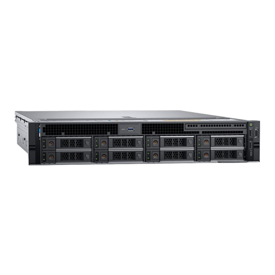
PowerEdge R740 system overview The PowerEdge R740 is a 2U rack server that supports up to: • Two Intel Xeon Scalable Processors • 24 DIMM slots • Two AC or DC power supply units • 16 SAS, SATA, Nearline SAS hard drives or SSDs. For more information about supported drives, see the Technical specifications section. - Page 9 Figure 1. Supported configurations PowerEdge R740 system overview...
-
Page 10: Front View Of The System
The Information Tag is a slide-out label panel that contains system Information tag information such as Service Tag, NIC, MAC address, and so on. If you have opted for the secure default access to iDRAC, the Information tag also contains the iDRAC secure default password. PowerEdge R740 system overview... - Page 11 Service Tag, NIC, MAC address, and so on. If you have opted for the secure default access to iDRAC, the Information tag also contains the iDRAC secure default password. Figure 4. Front view of 8 x 3.5 inch drive system PowerEdge R740 system overview...
-
Page 12: Left Control Panel View
This feature aggregates hardware/firmware inventory and various system level diagnostic/error information that can be used in troubleshooting the system. You can access system inventory, Dell Lifecycle Controller logs or system logs, system health status, and PowerEdge R740 system overview... -
Page 13: Status Led Indicators
Restart the system. Update any required drivers for the PCIe card. Reinstall indicator PCIe card experiences an error. the card. If the problem persists, see Getting help. NOTE: For more information about the supported PCIe cards, see Expansion card installation guidelines. PowerEdge R740 system overview... - Page 14 Event Log or the LCD panel, if available on the bezel, for specific error messages. For more information about error messages, see the Event and Error Message Reference Guide for 14th Generation Dell EMC PowerEdge Servers at Dell.com/qrl. iDRAC Quick Sync 2 indicator codes iDRAC Quick Sync 2 module (optional) is located on the left control panel of your system.
-
Page 15: Right Control Panel View
Table 8. Right control panel features Item Indicator, button, or Icon Description connector Power button Indicates if the system is turned on or off. Press the power button to manually turn on or off the system. PowerEdge R740 system overview... -
Page 16: Back View Of The System
Turns off Indicates that the laptop or tablet is unplugged. Back view of the system The back view of the system provides access to the features available on the back of the server. PowerEdge R740 system overview... - Page 17 User’s Guide at Dell.com/poweredgemanuals. The System Identification (ID) button is available on the front and back of System identification button the systems. Press the button to identify a system in a rack by turning on PowerEdge R740 system overview...
-
Page 18: Nic Indicator Codes
AC power supply units (PSUs) have an illuminated translucent handle that serves as an indicator. The DC PSUs have an LED that serves as an indicator. The indicator shows whether power is present or if a power fault has occurred. PowerEdge R740 system overview... - Page 19 CAUTION: If two PSUs are used, they must be of the same type and have the same maximum output power. CAUTION: Combining AC and DC PSUs is not supported and triggers a mismatch. PowerEdge R740 system overview...
- Page 20 CAUTION: If two PSUs are used, they must be of the same type and have the same maximum output power. CAUTION: Combining AC and DC PSUs is not supported and triggers a mismatch. PowerEdge R740 system overview...
-
Page 21: Drive Indicator Codes
Predicted drive failure. Flashes amber four times per second Drive failed. Flashes green slowly Drive rebuilding. Solid green Drive online. Flashes green for three seconds, amber for three seconds, and Rebuild stopped. then turns off after six seconds PowerEdge R740 system overview... -
Page 22: Lcd Panel
Release the button to stop. NOTE: The display stops scrolling when the button is released. After 45 seconds of inactivity, the display starts scrolling. LCD display Displays system information, status, and error messages or iDRAC IP address. PowerEdge R740 system overview... -
Page 23: Viewing Home Screen
Select Simple to view LCD error messages in a simplified user-friendly description. For more information about error messages, see the Event and Error Message Reference Guide for 14th Generation Dell EMC PowerEdge Servers at Dell.com/qrl. Set home Select the default information to be displayed on the Home screen. See View menu section for the options and option items that can be set as the default on the Home screen. -
Page 24: Locating The Service Tag Of Your System
(back view) OpenManage Mobile (OMM) label iDRAC MAC address and iDRAC secure password label Service Tag System information label PowerEdge R740 – Front system information label LED behavior, express service tag, hard drives configuration and layout PowerEdge R740 system overview... - Page 25 Figure 16. LED behavior Figure 17. 2.5 inch hard drives configuration and layout Figure 18. 3.5 inch hard drives configuration and layout PowerEdge R740 system overview...
-
Page 26: Poweredge R740 – Service Information
PowerEdge R740 – Service information System touchpoint, electrical overview, mechanical overview and rear view configurations Figure 19. Service Information PowerEdge R740 system overview... - Page 27 Figure 20. Jumper setting and memory information Figure 21. system task PowerEdge R740 system overview...
- Page 28 Figure 22. NVDIMM battery and mid-tray hard drives PowerEdge R740 system overview...
-
Page 29: Documentation Resources
To view the document that is listed in the documentation resources table: • From the Dell EMC support site: Click the documentation link that is provided in the Location column in the table. Click the required product or product version. - Page 30 Dell OpenManage Essentials, see Essentials the Dell OpenManage Essentials User’s Guide. For information about installing and using Dell Dell.com/serviceabilitytools SupportAssist, see the Dell EMC SupportAssist Enterprise User’s Guide. For information about partner programs enterprise Dell.com/openmanagemanuals systems management, see the OpenManage Connections Enterprise Systems Management documents.
-
Page 31: Technical Specifications
Technical specifications The technical and environmental specifications of your system are outlined in this section. Topics: • System dimensions • Chassis weight • Processor specifications • Supported operating systems • PSU specifications • System battery specifications • Expansion bus specifications •... -
Page 32: Chassis Weight
Figure 23. System dimensions of PowerEdge R740 system Table 17. Dimensions System Za (with Za (without bezel) bezel) PowerEdge R740 482.0 mm 434.0 mm 86.8 mm 35.84 mm 22.0 mm 678.8 mm 715.5 mm (3.42 inches) (26.72 (28.17 inches) (18.98 (17.09 inches) -
Page 33: Processor Specifications
Processor specifications The PowerEdge R740 system supports up to two Intel Xeon Processor Scalable Family processors, up to 28 cores per processor. Supported operating systems The PowerEdge R740 supports the following operating systems: Canonical Ubuntu LTS Citrix XenServer Microsoft Windows Server with Hyper-V... -
Page 34: System Battery Specifications
Expansion bus specifications The PowerEdge R740 system supports up to eight PCI express (PCIe) generation 3 expansion cards that can be installed on the system board using expansion card risers. The following table provides detailed information about the expansion card riser specifications: Table 20. - Page 35 Expansion card PCIe slots on the Height Length Link riser riser Slot 8 Full Height Full Length Table 21. Expansion card riser specifications Riser Slot description PCIe slots on Processor PCIe slots on riser Processor PCIe slots on Processor configuration riser 1 (Height connection 2 (Height and...
-
Page 36: Memory Specifications
NOTE: Minimum of two CPUs are required for any configurations that support NVDIMM-N. Storage controller specifications The PowerEdge R740 system supports: • Internal storage controller cards: PowerEdge RAID Controller (PERC) H330, PERC H730P, PERC H740P, HBA330, S140, and Boot Optimized Server Storage (BOSS-S1). -
Page 37: Drive Specifications
Two USB 3.0-compliant ports on the back of the system NIC ports The PowerEdge R740 system supports up to four Network Interface Controller (NIC) ports that are integrated on the network daughter card (NDC), and are available in the following configurations: •... -
Page 38: Vga Ports
VGA ports The Video Graphic Array (VGA) port enables you to connect the system to a VGA display. The PowerEdge R740 system supports two 15- pin VGA ports on the front and back panels. Serial connector The PowerEdge R740 system supports one serial connector on the back panel, which is a 9-pin connector, Data Terminal Equipment (DTE), 16550-compliant. -
Page 39: Environmental Specifications
Environmental specifications NOTE: For additional information about environmental certifications, please refer to the Product Environmental Datasheet located with the Manuals & Documents on Dell.com/poweredgemanuals. Table 25. Temperature specifications Temperature Specifications Storage –40°C to 65°C (–40°F to 149°F) Continuous operation (for altitude less than 950 m or 3117 10°C to 35°C (50°F to 95°F) with no direct sunlight on the equipment. -
Page 40: Standard Operating Temperature
Table 30. Operating temperature de-rating specifications Operating temperature de-rating Specifications Up to 35°C (95°F) Maximum temperature is reduced by 1°C/300 m (1°F/547 ft) above 950 m (3,117 ft). 35°C to 40°C (95°F to 104°F) Maximum temperature is reduced by 1°C/175 m (1°F/319 ft) above 950 m (3,117 ft). - Page 41 • Do not perform a cold startup below 5°C. • The operating temperature specified is for a maximum altitude of 3050 m (10,000 ft). • 150 W/8 core, 165 W/12 core and higher wattage processor [Thermal Design Power (TDP)>165 W] are not supported. •...
-
Page 42: Particulate And Gaseous Contamination Specifications
System Front backplane CPU Thermal CPU heat sink Fan type Ambient Design Power restriction (TDP) 16 x 2.5 inch SAS/ 150 W/8 core, 165 1U high High performance ≥1 double-width/ 30°C SATA W/12 core, 200 performance single-width W, 205 W Particulate and gaseous contamination specifications The following table defines the limitations that help avoid any equipment damage or failure from particulate and gaseous contamination. -
Page 43: Initial System Setup And Configuration
Initial system setup and configuration Setting up your system Perform the following steps to set up your system: Unpack the system. Install the system into the rack. For more information about installing the system into the rack, see the Rail Installation Guide at Dell.com/poweredgemanuals. -
Page 44: Options To Install The Operating System
Ensure that you change the default user name and password after setting up the iDRAC IP address. NOTE: The Intel Quick Assist Technology (QAT) on the Dell EMC PowerEdge R740 is supported with chipset integration and is enabled through an optional license. The license files are enabled on the sleds through iDRAC. -
Page 45: Downloading Drivers And Firmware
Using iDRAC virtual media Dell.com/idracmanuals Downloading drivers and firmware Dell EMC recommends that you download and install the latest BIOS, drivers, and systems management firmware on your system. Prerequisite Ensure that you clear the web browser cache before downloading the drivers and firmware. -
Page 46: Pre-Operating System Management Applications
Pre-operating system management applications You can manage basic settings and features of a system without booting to the operating system by using the system firmware. Topics: • Options to manage the pre-operating system applications • System Setup • Dell Lifecycle Controller •... -
Page 47: System Setup Details
System Setup details The System Setup Main Menu screen details are explained as follows: Option Description System BIOS Enables you to configure BIOS settings. iDRAC Settings Enables you to configure the iDRAC settings. The iDRAC settings utility is an interface to set up and configure the iDRAC parameters by using UEFI (Unified Extensible Firmware Interface). -
Page 48: System Information
Option Description Network Settings Provides options to manage the UEFI network settings and boot protocols. Legacy network settings are managed from the Device Settings menu. Integrated Devices Provides options to manage integrated device controllers and ports, specifies related features and options. Serial Provides options to manage the serial ports, their related features and options. - Page 49 Option Description System Specifies the name of the system manufacturer. Manufacturer System Specifies the contact information of the system manufacturer. Manufacturer Contact Information System CPLD Specifies the current version of the system complex programmable logic device (CPLD) firmware. Version UEFI Compliance Specifies the UEFI compliance level of the system firmware.
-
Page 50: Processor Settings
Option Description NOTE: The Memory Operating Mode option can have different default and available options based on the memory configuration of your system. NOTE: The Dell Fault Resilient Mode option establishes an area of memory that is fault resilient. This mode can be used by an operating system that supports the feature to load critical applications or enables the operating system kernel to maximize system availability. - Page 51 Option Description Logical Processor Enables or disables the logical processors and displays the number of logical processors. If this option is set to Enabled, the BIOS displays all the logical processors. If this option is set to Disabled, the BIOS displays only one logical processor per core.
- Page 52 Option Description Processor n NOTE: Depending on the number of processors, there might be up to four processors listed. The following settings are displayed for each processor installed in the system: Option Description Family-Model- Specifies the family, model, and stepping of the processor as defined by Intel. Stepping Brand Specifies the brand name.
-
Page 53: Boot Settings
Option Description Option Description Drive Type Specifies the type of drive attached to the SATA port. Capacity Specifies the total capacity of the drive. This field is undefined for removable media devices such as optical drives. Boot Settings You can use the Boot Settings screen to set the boot mode to either BIOS or UEFI. It also enables you to specify the boot order. •... - Page 54 Option Description Hard-Disk Failover Specifies the drive that is booted in the event of a drive failure. The devices are selected in the Hard-Disk Drive Sequence on the Boot Option Setting menu. When this option is set to Disabled, only the first drive in the list is attempted to boot.
-
Page 55: Network Settings
Network Settings You can use the Network Settings screen to modify UEFI PXE, iSCSI, and HTTP boot settings. The network settings option is available only in the UEFI mode. NOTE: BIOS does not control network settings in the BIOS mode. For the BIOS boot mode, the option ROM of the network controllers handles the network settings. - Page 56 NOTE: If your operating system begins to load before you press F2, wait for the system to finish booting, and then restart your system and try again. On the System Setup Main Menu screen, click System BIOS. On the System BIOS screen, click Network Settings. On the Network Settings screen, click UEFI iSCSI Settings.
- Page 57 Option Description Integrated RAID Enables or disables the integrated RAID controller. This option is set to Enabled by default. Controller Integrated Network Enables or disables the integrated network card (NDC). When set to Disabled, the NDC is not available to the Card 1 operating system (OS).
- Page 58 Option Description Table 39. Slot Disablement Option Description Enables or disables the PCIe slot 1. This option is set to Slot 1 Enabled by default. Slot 3 Enables or disables or only the boot driver is disabled for the PCIe slot 3. This option is set to Enabled by default.
- Page 59 Serial Communication You can use the Serial Communication screen to view the properties of the serial communication port. Viewing Serial Communication To view the Serial Communication screen, perform the following steps: Power on, or restart your system. Press F2 immediately after you see the following message: F2 = System Setup NOTE: If your operating system begins to load before you press F2, wait for the system to finish booting, and then restart...
- Page 60 System Profile Settings You can use the System Profile Settings screen to enable specific system performance settings such as power management. Viewing System Profile Settings To view the System Profile Settings screen, perform the following steps: Power on, or restart your system. Press F2 immediately after you see the following message: F2 = System Setup NOTE:...
-
Page 61: System Security
Option Description Energy Efficient Enables you to select the Energy Efficient Policy option. Policy The CPU uses the setting to manipulate the internal behavior of the processor and determines whether to target higher performance or better power savings. This option is set to Balanced Performance by default. Number of Turbo NOTE: If there are two processors installed in the system, you will see an entry for Number of Turbo... - Page 62 Option Description NOTE: BIOS update requires HECI devices to be operational and DUP updates require IPMI interface to be operational. This setting needs to be set to Enabled to avoid updating errors. Intel(R) AES-NI Improves the speed of applications by performing encryption and decryption by using the Advanced Encryption Standard Instruction Set (AES-NI).
-
Page 63: Options Description
Option Description Secure Boot Policy When Secure Boot policy is set to Standard, the BIOS uses the system manufacturer key and certificates to authenticate pre-boot images. When Secure Boot policy is set to Custom, the BIOS uses the user-defined key and certificates. - Page 64 Reenter the system password, and click OK. In the Setup Password field, type your setup password and press Enter or Tab. A message prompts you to reenter the setup password. Reenter the setup password, and click OK. Press Esc to return to the System BIOS screen. Press Esc again. A message prompts you to save the changes.
- Page 65 • If System Password is not set to Enabled and is not locked through the Password Status option, you can assign a system password. For more information, see the System Security Settings details section. • You cannot disable or change an existing system password. NOTE: You can use the password status option with the setup password option to protect the system password from unauthorized changes.
-
Page 66: Idrac Settings Utility
Miscellaneous Settings You can use the Miscellaneous Settings screen to perform specific functions such as updating the asset tag and changing the system date and time. Viewing Miscellaneous Settings To view the Miscellaneous Settings screen, perform the following steps: Power on, or restart your system. Press F2 immediately after you see the following message: F2 = System Setup NOTE:... -
Page 67: Device Settings
For more information about using iDRAC, see Dell Integrated Dell Remote Access Controller User's Guide at Dell.com/poweredgemanuals. Device Settings Device Settings enables you to configure the below device parameters: • Controller Configuration Utility • Embedded NIC Port1-X Configuration • NICs in slotX, Port1-X Configuration •... -
Page 68: Boot Manager Main Menu
Boot Manager main menu Menu item Description Continue Normal The system attempts to boot to devices starting with the first item in the boot order. If the boot attempt fails, the Boot system continues with the next item in the boot order until the boot is successful or no more boot options are found. -
Page 69: Installing And Removing System Components
Installing and removing system components Safety instructions WARNING: Whenever you need to lift the system, get others to assist you. To avoid injury, do not attempt to lift the system by yourself. WARNING: Opening or removing the system cover while the system is powered on may expose you to a risk of electric shock. CAUTION: Do not operate the system without the cover for a duration exceeding five minutes. -
Page 70: Recommended Tools
Recommended tools You need the following tools to perform the removal and installation procedures: • Key to the bezel lock The key is required only if your system includes a bezel. • Phillips #1 screwdriver • Phillips #2 screwdriver • Torx #T30 screwdriver •... -
Page 71: Installing The Front Bezel
Figure 24. Removing the optional front bezel with the LCD panel Next step Install the front bezel. Installing the front bezel The procedure to install the front bezel with and without the LCD panel is the same. Prerequisite Follow the safety guidelines listed in Safety instructions. -
Page 72: System Cover
Figure 25. Installing the optional front bezel with the LCD panel System cover Removing the system cover Prerequisites Follow the safety guidelines listed in Safety instructions. Turn off the system, including any attached peripherals. Disconnect the system from the electrical outlet and disconnect the peripherals. Steps Using a 1/4 inch flat head or a Phillips #2 screwdriver, rotate the latch release lock counter clockwise to the unlocked position. -
Page 73: Installing The System Cover
Figure 26. Removing the system cover Next step Install the system cover. Installing the system cover Prerequisites Follow the safety guidelines listed in Safety instructions. Ensure that all internal cables are routed correctly and connected, and no tools or extra parts are left inside the system. Steps Align the tabs on the system cover with the guide slots on the system. -
Page 74: Backplane Cover
Figure 27. Installing system cover Next steps Reconnect the peripherals and connect the system to the electrical outlet. Turn on the system, including any attached peripherals. Backplane cover Removing the backplane cover Prerequisites Follow the safety guidelines listed in Safety instructions. -
Page 75: Installing The Backplane Cover
Figure 28. Removing backplane cover Next step Install the backplane cover. Installing the backplane cover Prerequisite Follow the safety guidelines listed in Safety instructions. Steps Align the tabs on the backplane cover with the guide slots on the system. Slide the backplane cover toward the front of the system until the cover locks into place. Installing and removing system components... -
Page 76: Inside The System
Figure 29. Installing the backplane cover Next step Follow the procedure listed in After working inside your system. Inside the system CAUTION: Many repairs may only be done by a certified service technician. You should only perform troubleshooting and simple repairs as authorized in your product documentation, or as directed by the online or telephone service and support team. - Page 77 Figure 30. Inside the system drive backplane backplane expander card cooling fan in the cooling fan assembly (6) memory module CPU2 processor and heat sink module socket (with dust cover) 6 expansion card riser 3 network daughter card expansion card riser 2 system board expansion card riser 1 integrated storage controller card...
-
Page 78: Air Shroud
Figure 31. Inside the system – Configuration showing air shroud with optional NVDIMM-N battery drive backplane backplane expander card cooling fan (6) in the cooling fan assembly air shroud expansion card riser 3 network daughter card expansion card riser 2 system board expansion card riser 1 integrated storage controller card... -
Page 79: Installing The Air Shroud
Follow the safety guidelines listed in Safety instructions. Follow the procedure listed in Before working inside your system. If installed, remove the full length PCIe cards. If applicable, remove the GPU cards. If NVDIMM-N battery is installed, disconnect the cables from the NVDIMM-N battery. CAUTION: NVDIMM-N battery is not hot swappable. -
Page 80: Cooling Fan Assembly
Figure 33. Installing air shroud Next steps If removed, install the full length PCIe cards. If applicable, install the GPU cards. If applicable, connect the cables to the NVDIMM-N battery. CAUTION: NVDIMM-N battery is not hot swappable. To prevent data loss and potential damage to your system, ensure that your system, LEDs on system, LEDs on NVDIMM-N and LEDs on NVDIMM-N battery are turned off before connecting the NVDIMM-N battery cables. -
Page 81: Installing The Cooling Fan Assembly
Figure 34. Removing the cooling fan assembly Next step Install the cooling fan assembly. Installing the cooling fan assembly Prerequisite Follow the safety guidelines listed in Safety instructions. CAUTION: Ensure that the cables inside the system are correctly installed and retained by the cable retention bracket before installing the cooling fan assembly. -
Page 82: Cooling Fans
Figure 35. Installing the cooling fan assembly Next step Follow the procedure listed in After working inside your system. Cooling fans Cooling fan details The cooling fans are integrated into the system to dissipate the heat generated by the functioning of the system. These fans provide cooling for the processors, expansion cards, and memory modules. -
Page 83: Removing A Cooling Fan
Removing a cooling fan The procedure for removing standard and high performance fans is identical. Prerequisites WARNING: Opening or removing the system cover when the system is on may expose you to a risk of electric shock. Exercise utmost care while removing or installing cooling fans. CAUTION: The cooling fans are hot swappable. -
Page 84: Intrusion Switch
Figure 37. Installing cooling fan Slide the cooling fan into the cooling fan assembly until the release tab locks into place. Next step Follow the procedure listed in After working inside your system. Intrusion switch Removing an intrusion switch Prerequisites Follow the safety guidelines listed in Safety instructions. -
Page 85: Installing An Intrusion Switch
Figure 38. Removing an intrusion switch Next step Install an intrusion switch. Installing an intrusion switch Prerequisite Follow the safety guidelines listed in Safety instructions. Steps Align the tabs on the intrusion switch with the slots on the cooling fan assembly. Push the intrusion switch until it locks in place. -
Page 86: Nvdimm-N Battery
Figure 39. Installing an intrusion switch Next steps Install the cooling fan assembly. Follow the procedure listed in After working inside your system. NVDIMM-N battery NVDIMM-N battery details NVDIMM-N battery can be installed on both regular and GPU air shrouds. Removing the NVDIMM-N battery from the air shroud Prerequisites Follow the safety guidelines listed in... -
Page 87: Installing Nvdimm-N Battery Into Air Shroud
Figure 40. Removing the NVDIMM-N battery from the air shroud Next step Install the NVDIMM-N battery into the air shroud. Installing NVDIMM-N battery into air shroud Prerequisites Follow the safety guidelines listed in Safety instructions. CAUTION: NVDIMM-N battery is not hot swappable. To prevent data loss and potential damage to your system, ensure that your system, LEDs on system, LEDs on NVDIMM-N and LEDs on NVDIMM-N battery are turned off before installing the NVDIMM-N battery. -
Page 88: Removing Nvdimm-N Battery From Mid Drive Tray
Figure 41. Installing NVDIMM-N battery into air shroud Next step Follow the procedure listed in After working inside your system. Removing NVDIMM-N battery from mid drive tray Prerequisites Follow the safety guidelines listed in Safety instructions. Follow the procedure listed in Before working inside your system. -
Page 89: Installing Nvdimm-N Battery Into Mid Drive Tray
Figure 42. Removing NVDIMM-N battery from mid drive tray Next step Install NVDIMM-N battery into mid drive tray. Installing NVDIMM-N battery into mid drive tray Prerequisites Follow the safety guidelines listed in Safety instructions. CAUTION: NVDIMM-N battery is not hot swappable. To prevent data loss and potential damage to your system, ensure that your system, LEDs on system, LEDs on NVDIMM-N and LEDs on NVDIMM-N battery are turned off before installing the NVDIMM-N battery. -
Page 90: Removing Nvdimm-N Battery From The Bracket
Figure 43. Installing NVDIMM-N battery into mid drive tray Next step Follow the procedure listed in After working inside your system. Removing NVDIMM-N battery from the bracket Prerequisites Follow the safety guidelines listed in Safety instructions. Follow the procedure listed in Before working inside your system. -
Page 91: Installing Nvdimm-N Battery Into The Bracket
Figure 44. Removing NVDIMM-N battery from the bracket Next step Install NVDIMM-N battery into the bracket.. Installing NVDIMM-N battery into the bracket Prerequisites Follow the safety guidelines listed in Safety instructions. CAUTION: NVDIMM-N battery is not hot swappable. To prevent data loss and potential damage to your system, ensure that your system, LEDs on system, LEDs on NVDIMM-N and LEDs on NVDIMM-N battery are turned off before installing the NVDIMM-N battery. -
Page 92: Drives
Figure 45. Installing NVDIMM-N battery into the bracket Next step Follow the procedure listed in After working inside your system. Drives Drive guidelines Drives are supplied in hot swappable drive carriers that fit in the drive slots. CAUTION: Before attempting to remove or install a drive while the system is running, see the documentation for the storage controller card to ensure that the host adapter is configured correctly. -
Page 93: Installing A Drive Blank
Figure 46. Removing a drive blank Next step Install a drive or a drive blank Installing a drive blank The procedure for installing 2.5 inch and 3.5 inch drive blanks is identical. Prerequisite Follow the safety guidelines listed in Safety instructions. -
Page 94: Installing A Drive Carrier
Using the management software, prepare the drive for removal. If the drive is online, the green activity or fault indicator flashes while the drive is turning off. When the drive indicators are off, the drive is ready for removal. For more information, see the documentation for the storage controller. CAUTION: Before attempting to remove or install a drive while the system is running, see the documentation for the storage controller card to ensure that the host adapter is configured correctly to support drive removal and insertion. -
Page 95: Removing A 2.5 Inch Drive From The 3.5 Inch Drive Adapter
CAUTION: When a replacement hot swappable drive is installed and the system is powered on, the drive automatically begins to rebuild. Ensure that the replacement drive is blank or contains data that you wish to overwrite. Any data on the replacement drive is immediately lost after the drive is installed. -
Page 96: Installing A 2.5 Inch Drive Into The 3.5 Inch Drive Adapter
Figure 50. Removing a 2.5 inch drive from the 3.5 inch drive adapter Next step Install a 2.5 inch drive into the 3.5 inch drive adapter. Installing a 2.5 inch drive into the 3.5 inch drive adapter Prerequisite Follow the safety guidelines listed in Safety instructions. -
Page 97: Removing A 3.5 Inch Adapter From A 3.5 Inch Drive Carrier
Figure 51. Installing a 2.5 inch drive into the 3.5 inch drive adapter Next steps Install a 3.5 inch adapter into the 3.5 inch drive carrier. Follow the procedure listed in After working inside your system. Removing a 3.5 inch adapter from a 3.5 inch drive carrier Prerequisites Follow the safety guidelines listed in Safety... -
Page 98: Installing A 3.5 Inch Adapter Into A 3.5 Inch Drive Carrier
Figure 52. Removing a 3.5 inch adapter from a 3.5 inch drive carrier Next step Install a 3.5 inch adapter into a 3.5 inch drive carrier. Installing a 3.5 inch adapter into a 3.5 inch drive carrier Prerequisite Follow the safety guidelines listed in Safety instructions. -
Page 99: Removing The Drive From The Drive Carrier
Figure 53. Installing a 3.5 inch adapter into a 3.5 inch drive carrier Next steps Install a 3.5 inch drive carrier into the system. Follow the procedure listed in After working inside your system. Removing the drive from the drive carrier Prerequisites Follow the safety guidelines listed in Safety... -
Page 100: Installing A Drive Into The Drive Carrier
Figure 54. Removing the drive from the drive carrier Next step If applicable, install the drive into the drive carrier. Installing a drive into the drive carrier Prerequisites Follow the safety guidelines listed in Safety instructions. CAUTION: Mixing drive carriers from other generations of PowerEdge servers is not supported. NOTE: When installing a drive into the drive carrier, ensure that the screws are torqued to 4 in-lbs. -
Page 101: System Memory
Figure 55. Installing a drive into the drive carrier System memory System memory guidelines The PowerEdge systems support DDR4 Registered DIMMs (RDIMMs), Load Reduced DIMMs (LRDIMMs), and Non-Volatile DIMMs (NVDIMM-Ns). System memory holds the instructions that are executed by the processor. Your system contains 24 memory sockets split into two sets of 12 sockets, one set per processor. - Page 102 Figure 56. Memory socket locations Memory channels are organized as follows: Table 41. Memory channels Processor Channel 0 Channel 1 Channel 2 Channel 3 Channel 4 Channel 5 Processor 1 Slots A1 and A7 Slots A2 and A8 Slots A3 and A9 Slots A4 and A10 Slots A5 and A11 Slots A6 and A12...
-
Page 103: General Memory Module Installation Guidelines
General memory module installation guidelines To ensure optimal performance of your system, observe the following general guidelines when configuring your system memory. If your system's memory configurations fail to observe these guidelines, your system might not boot, stop responding during memory configuration, or operate with reduced memory. -
Page 104: Nvdimm-N Memory Module Installation Guidelines
NVDIMM-N memory module installation guidelines The following are the recommended guidelines for installing NVDIMM-N memory modules: • Each system supports memory configurations with 1, 2, 4, 6, or 12 NVDIMM-Ns. • Supported configurations have dual processors and a minimum of 12x RDIMMs. •... -
Page 105: Mode-Specific Guidelines
Configuration Description Memory population rules RDIMMs NVDIMM-N Processor1 {A11, 12} Configuration 9 20x 32 GB RDIMMs, 4x Processor1 {A1, 2, 3, 4, 5, 6, 7, 8, NVDIMM-Ns 9, 10} Processor2 {B11, 12} Processor2 {B1, 2, 3, 4, 5, 6, 7, 8, 9, 10} Same for all 12x RDIMM Processor1 {A7, 8, 9}... - Page 106 Memory Operating Mode Description prevent errors from causing an uncorrectable failure. Requires two or more ranks to be populated in each channel. Multi Rank Spare Mode Multi Rank Spare Mode allocates two ranks per channel as a spare. If excessive correctable errors occur in a rank or channel, while the operating system is running, they are moved to the spare area to prevent errors from causing an uncorrectable failure.
- Page 107 Processor Configuration Memory population Memory population information – For 8 DIMMs: A1, A2, A4, A5, A7, A8, A10, Mirror population order {1, 2, 3, 4, 5, 6} {7, 8, 9, 10, Mirroring is supported with 6 or 12 DIMMs per 11, 12} processor.
-
Page 108: Removing A Memory Module
Processor Configuration Memory population Memory population information Fault resilient population Supported with 6 or 12 DIMMs per processor. A{1, 2, 3, 4, 5, 6}, order B{1, 2, 3, 4, 5, 6}, A{7, 8, 9, 10, 11, 12}, B{7, 8, 9, 10, 11, 12} Removing a memory module The procedure for removing a DIMM module and an NVDIMM-N module is identical. -
Page 109: Installing A Memory Module
Installing a memory module The procedure for installing a DIMM module and an NVDIMM-N module is identical. Prerequisites Follow the safety guidelines listed in Safety instructions. CAUTION: Ensure that you install the NVDIMM-N battery if you are using NVDIMM-N. CAUTION: To prevent data loss and potential damage to your system, ensure that your system, LEDs on system, LEDs on NVDIMM-N and LEDs on NVDIMM-N battery are turned off before installing the NVDIMM-N battery. -
Page 110: Removing The Processor From The Processor And Heat Sink Module
Steps Using a Torx #T30 screwdriver, loosen the screws on the heat sink in the order below: Loosen the first screw three turns. b Loosen the second screw completely. Return to the first screw and loosen it completely. NOTE: It is normal for the heat sink to slip off the blue retention clips when the screws are partially loosened, continue to loosen the screw(s). - Page 111 Figure 59. Loosening the processor bracket Lift the bracket and the processor away from the heat sink, and place the processor connector side down on the processor tray. Flex the outer edges of the bracket to release the bracket from the processor. NOTE: Ensure that the processor and the bracket are placed in the tray after you remove the heat sink.
-
Page 112: Installing The Processor Into A Processor And Heat Sink Module
Installing the processor into a processor and heat sink module Prerequisite Follow the safety guidelines listed in Safety instructions. Steps Place the processor in the processor tray. NOTE: Ensure that the pin 1 indicator on the processor tray is aligned with the pin 1 indicator on the processor. Flex the outer edges of the bracket around the processor ensuring that the processor is locked into the clips on the bracket. - Page 113 Figure 62. Applying thermal grease on top of the processor Place the heat sink on the processor and push down on the base of the heat sink until the bracket locks onto the heat sink. NOTE: • Ensure that the two guide pin holes on the bracket match the guide holes on the heat sink. •...
-
Page 114: Installing A Processor And Heat Sink Module
Figure 63. Installing the heat sink onto the processor Next step Install the processor and heat sink module. Installing a processor and heat sink module Prerequisites CAUTION: Never remove the heat sink from a processor unless you intend to replace the processor. The heat sink is necessary to maintain proper thermal conditions. -
Page 115: Expansion Cards And Expansion Card Risers
However, if a F1/F2 pause occurs and an error message is displayed. The PowerEdge R740 system supports up to eight PCI express (PCIe) generation 3 expansion cards, that can be installed on the system board using expansion card risers. The following table provides detailed information about the expansion card riser specifications:... - Page 116 Table 45. Expansion card riser specifications Riser Slot description PCIe slots on Processor PCIe slots on riser Processor PCIe slots on Processor configuration riser 1 (Height connection 2 (Height and connection riser 3 (Height connection and supported and length) length) and length) risers Riser...
- Page 117 Riser Slot description PCIe slots on Processor PCIe slots on riser Processor PCIe slots on Processor configuration riser 1 (Height connection 2 (Height and connection riser 3 (Height connection and supported and length) length) and length) risers Slot 1: x16 full- Processor 1 Slot 4: x16 full- Processor 2 Slot 7: x8 full- Processor...
- Page 118 Card Type Slot priority Maximum number of cards BOSS Table 47. Riser configurations with greater than 4 PCIe slots [Riser configuration 3 (1A+2A), Riser configuration 4 (1A+2A+3A), Riser configuration 5 (1B+2A+3A), Riser configuration 6 (1D+2A+3A) and Riser configuration 9 (1A+2D+3A)] Card Type Slot priority Maximum number of cards...
-
Page 119: Opening And Closing The Pcie Card Holder Latch
NOTE: Double width GPUs are supported only on riser configuration 4, and single width GPUs are supported only on riser configuration 6. NOTE: Ensure that x16 cards are installed only in x16 slots. Depending on the riser configuration slots 2, 7, or 8 may not be available. -
Page 120: Removing Expansion Card From The Expansion Card Riser
Figure 66. Closing the PCIe card holder latch Next step Follow the procedure listed in After working inside your system. Removing expansion card from the expansion card riser Prerequisites Follow the safety guidelines listed in Safety instructions. Follow the procedure listed in Before working inside your system. - Page 121 Figure 67. Removing the expansion card from expansion card riser 1 Figure 68. Removing the expansion card from expansion card riser 2B Installing and removing system components...
- Page 122 Figure 69. Removing the expansion card from expansion card riser 2 Figure 70. Removing the expansion card from expansion card riser 3 Next steps Install the expansion card into the expansion card riser. If you are removing the card permanently, install a metal filler bracket over the empty expansion slot opening and push the expansion card latch.
-
Page 123: Installing Expansion Card Into The Expansion Card Riser
Installing expansion card into the expansion card riser Prerequisites Follow the safety guidelines listed in Safety instructions. If installing a new expansion card, unpack it and prepare the card for installation. NOTE: For instructions, see the documentation accompanying the card. When installing a card into riser 2 or 3, open the PCIe card holder latch. - Page 124 Figure 72. Installing expansion card into expansion card riser 2B Figure 73. Installing expansion card into expansion card riser 2 Installing and removing system components...
-
Page 125: Removing Riser 2 And 3 Blank
Figure 74. Installing expansion card into expansion card riser 3 Next steps If applicable, connect the cables to the expansion card. If applicable, install the air shroud. Follow the procedure listed in After working inside your system. Install any device drivers required for the card as described in the documentation for the card. Removing riser 2 and 3 blank Prerequisites Follow the safety guidelines listed in... -
Page 126: Installing Riser 2 And 3 Blank
Figure 75. Removing riser 2 and 3 blank Next step Install the riser 2 and 3 blank. Installing riser 2 and 3 blank Prerequisite Follow the safety guidelines listed in Safety instructions. Steps Align the screw and guide rail on the riser blank with the screw hole and standoff on the system. Lower the blank into the system until the release tab clicks into place. -
Page 127: Removing Riser 3 Blank
Figure 76. Installing riser 2 and 3 blank Next steps Install the air shroud. Follow the procedure listed in After working inside your system. Removing riser 3 blank Prerequisites Follow the safety guidelines listed in Safety instructions. Follow the procedure listed in Before working inside your system. -
Page 128: Installing Riser 3 Blank
Figure 77. Removing riser 3 blank Next step Install the riser 3 blank. Installing riser 3 blank Prerequisite Follow the safety guidelines listed in Safety instructions. Steps Align the screw on the riser with the screw hole on the system. Using Phillips #2 screwdriver, tighten the screw to secure the blank to the system. -
Page 129: Removing Expansion Card Riser 1
Figure 78. Installing riser 3 blank Next step Follow the procedure listed in After working inside your system. Removing expansion card riser 1 Prerequisites Follow the safety guidelines listed in Safety instructions. Follow the procedure listed in Before working inside your system. -
Page 130: Installing Expansion Card Riser 1
Figure 79. Removing expansion card riser 1 Next step Install the expansion card riser Installing expansion card riser 1 Prerequisite Follow the safety guidelines listed in Safety instructions. Steps Align the guide rails on the riser with the standoffs on the side of the system. Lower the riser into the system until the riser connector engages with the connector on the system board. -
Page 131: Removing Expansion Card Riser 2
Figure 80. Installing expansion card riser 1 Next steps If removed, install expansion cards into the riser. Follow the procedure listed in After working inside your system. Install any device drivers required for the card as described in the documentation for the card. Removing expansion card riser 2 Prerequisites Follow the safety guidelines listed in... -
Page 132: Installing Expansion Card Riser 2
Figure 81. Removing expansion card riser 2A To remove expansion card riser 2B or 2C, hold the riser by its edges and lift the riser from the riser connector on the system board. Figure 82. Removing expansion card riser 2 Next step Install the expansion card riser Installing expansion card riser 2... - Page 133 b Lower the riser into the system until the riser connector engages with the connector on the system board. Using Phillips #2 screwdriver, tighten the screws to secure the riser to the system. Figure 83. Installing expansion card riser 2A To install expansion card riser 2B or 2C: Align the slot on the riser with the standoff on the system.
-
Page 134: Removing Expansion Card Riser 3
Removing expansion card riser 3 Prerequisites Follow the safety guidelines listed in Safety instructions. Follow the procedure listed in Before working inside your system. Remove the air shroud. NOTE: If applicable, close the PCIe card holder latch on the air shroud to release the full length card. If installed, remove expansion cards installed on the riser. -
Page 135: Gpu Card Installation Guidelines
Using Phillips #2 screwdriver, tighten the screw to secure the riser to the system. Figure 86. Installing expansion card riser 3 Next steps If removed, install expansion cards into the riser. Install the air shroud. NOTE: If applicable, open the PCIe card holder latch on the air shroud to install the full length card. Follow the procedure listed in After working inside your system. -
Page 136: Removing A Gpu
– Six high performance cooling fans • All GPUs must be of the same type and model. • You can install up to three double-wide or six single-wide GPUs. • The filler bracket on the GPU air shroud must be removed before installing the GPU. •... - Page 137 Figure 88. Removing GPU 1 Figure 89. Removing GPU 2 and 3 Disconnect the GPU power cable from the GPU and system board. If you are removing the GPU permanently, install a filler bracket over the empty slot opening, and close the expansion card latch. NOTE: You must install a filler bracket over an empty expansion card slot to maintain Federal Communications Commission (FCC) certification of the system.
-
Page 138: Installing A Gpu
Installing a GPU Prerequisites Follow the safety guidelines listed in Safety instructions. Remove the air shroud. Remove the heat sink. Remove the cooling fans and replace them with Install the cooling fans. Unpack the GPU cards and the GPU kit. Install the heat sink from the kit. - Page 139 Figure 91. Removing the top cover of the shroud If applicable, remove the shroud filler from the GPU air shroud slots. NOTE: Shroud fillers are available in the GPU air shroud for GPUs installed on riser 2 and Figure 92. Removing the shroud filler from GPU air shroud slots NOTE: Shroud fillers are available in the GPU air shroud for GPUs installed only on risers 2 and NOTE:...
- Page 140 NOTE: Ensure that you install the first GPU on riser NOTE: While installing a GPU on riser 3, place the GPU on the system with the GPU label side facing up. Steps Connect the GPU power cable to the connector on the system board. NOTE: While installing a GPU on riser 1, connect the GPU power cable to the connector on riser 1 and route the cable through the slot on the GPU air shroud.
- Page 141 Figure 94. Securing GPU 1 Installing and removing system components...
- Page 142 Figure 95. Installing GPU 2 and 3 Installing and removing system components...
- Page 143 Figure 96. Securing GPU 2 and 3 Next steps Install the top cover of the GPU air shroud. If available, remove the plastic cover fixed on the memory socket numbers marked on the air shroud. Figure 97. Installing the top cover of GPU air shroud To install mylar foam on the system cover: Place the system cover with the Service Information Label (SIL) side facing up.
-
Page 144: M.2 Ssd Module
For easier handling, peel off a small section of the adhesive cover and align the mylar foam with the system cover. Remove rest of the adhesive cover and install mylar foam on the system cover. Press along the length of the mylar foam to ensure that it is rmly affixed to the system cover. Figure 98. -
Page 145: Installing The M.2 Ssd Module
Figure 99. Removing the M.2 SSD module Next step Install the M.2 SSD module. Installing the M.2 SSD module Prerequisite Follow the safety guidelines listed in Safety instructions. Steps Align the M.2 SSD module connectors with the connectors on the BOSS card. Push the M.2 SSD module until the module is seated firmly on the BOSS card. -
Page 146: Optional Idsdm Or Vflash Module
Figure 100. Installing the M.2 SSD module Next steps Install the BOSS card. NOTE: Installing the BOSS card is similar to installing the expansion card riser. Install the air shroud Follow the procedure listed in After working inside your system. Optional IDSDM or vFlash module Removing the MicroSD card Prerequisites... -
Page 147: Installing The Microsd Card
Installing the MicroSD card Prerequisites Follow the safety guidelines listed in Safety instructions. NOTE: To use an MicroSD card with your system, ensure that the Internal SD Card Port is enabled in System Setup. NOTE: If reinstalling, ensure that you install the MicroSD cards into the same slots based on the labels you had marked on the cards during removal. -
Page 148: Installing Optional Idsdm Or Vflash Card
Figure 101. Removing the optional IDSDM/vFlash card NOTE: There are two dip switches on the IDSDM/vFlash card for write-protection. Next step Install the optional IDSDM/vFlash card. Installing optional IDSDM or vFlash card Prerequisite Follow the safety guidelines listed in Safety instructions. -
Page 149: Network Daughter Card
Figure 102. Installing optional IDSDM/vFlash card Next steps Install the MicroSD cards. NOTE: Reinstall the MicroSD cards into the same slots based on the labels you had marked on the cards during removal. If applicable, install the full height PCIe card. Follow the procedure listed in After working inside your system. -
Page 150: Installing The Network Daughter Card
Figure 103. Removing network daughter card Next step Install the Network Daughter Card. Installing the network daughter card Prerequisite Follow the safety guidelines listed in Safety instructions. Steps Orient the NDC so that the Ethernet connectors fit through the slot in the chassis. Align the captive screws at the back-end of the card with the screw holes on the system board. -
Page 151: Integrated Storage Controller Card
Figure 104. Installing the network daughter card Next steps If applicable, install the expansion card riser Follow the procedure listed in After working inside your system. Integrated storage controller card Removing integrated storage controller card Prerequisites Follow the safety guidelines listed in Safety instructions. -
Page 152: Installing Integrated Storage Controller Card
Figure 105. Removing integrated storage controller cable Lift one end of the card and angle it to disengage the card from the integrated storage controller card holder on the system board. Lift the card out of the system. Hold the interposer board by its edges, and pull the board until the connector on the board disengages from the connector on the system board. - Page 153 Steps Hold the interposer board by its edges, and align the interposer board connector with the connector on the system board. Press the touch point on the interposer board until the interposer board connector is firmly seated on the system board connector. Angle the card to engage the card with the integrated storage controller card holder on the system board.
-
Page 154: Backplane
Backplane Backplane details Depending on your system configuration, the backplanes supported in PowerEdge R740 are listed here: Table 48. Supported backplane options for PowerEdge R740 systems. System Supported backplane options 2.5 inch (x16) SAS/SATA backplane, or PowerEdge R740 2.5 inch (x8) SAS/SATA backplane, or 3.5 inch (x8) SAS/SATA backplane... -
Page 155: Removing The Backplane
Figure 111. Back view of 8 x 3.5 inch drive backplane SAS connector (BP SAS B) signal connector (J_BP_SIG) SAS connector (BP SAS A) power connector (J_BP_PWR_A) Removing the backplane The procedure to remove the backplane is identical for all backplane configurations. Prerequisites CAUTION: To prevent damage to the drives and backplane, remove the drives from the system before removing the backplane. -
Page 156: Installing The Backplane
Figure 112. Removing the backplane Next step Install the backplane. Installing the backplane The procedure to install the backplane is identical for all backplane configurations. Prerequisite Follow the safety guidelines listed in Safety instructions. Steps Use the hooks on the system as guides to align the backplane. Lower the backplane until the release tabs snap into place. -
Page 157: Cable Routing
Next steps Connect all the cables to the backplane. Install all the drives. Install the backplane cover. Install the cooling fan assembly. Install the air shroud. Follow the procedure listed in After working inside your system. Cable routing Figure 114. Cable routing – 8 x 2.5 inch drive backplane with mini PERC backplane backplane power cable (BP: BP1 to MB: BP1 ) backplane signal cable (BP: BPSIG1 to MB: BPSIG1) - Page 158 Figure 115. Cable routing – 8 x 2.5 inch drive backplane with adapter PERC backplane backplane signal cable (BP: BPSIG1 to MB: BPSIG1) backplane power cable (BP: BP1 to MB: BP1) system board adapter PERC SAS cable (BP: BP SAS A, BP SAS B to MB: RISER 2) Installing and removing system components...
- Page 159 Figure 116. Cable routing – 8 x 3.5 inch drive backplane with on board SATA backplane backplane power cable (BP: BP1 to MB: BP1) backplane signal cable (BP: BPSIG1 to MB: BPSIG1) system board SATA B cable (BP: BP SAS B to MB: J_BP_SIG1) SATA A cable (BP: BP SAS A to MB: BP 12C RVYPM) Installing and removing system components...
- Page 160 Figure 117. Cable routing – 8 x 3.5 inch drive backplane with mini PERC backplane backplane power cable (BP: BP to MB: BP1) backplane signal cable (BP: BPSIG1 to MB: BPSIG1) system board mini PERC SAS cable (BP: BP SAS A0, BP SAS B0 to MB: J_STORAGE1) Installing and removing system components...
- Page 161 Figure 118. Cable routing – 8 x 3.5 inch drive backplane with adapter PERC backplane backplane power cable (BP: BP1 to MB: BP1) backplane signal cable (BP: BPSIG1 to MB: BPSIG1) system board adapter PERC SAS A cable (BP: BP SAS A0 to MB: J_BP_PWR_A1) SAS B cable (BP: BP SAS B0 to MB: J_BP_SIG1) Installing and removing system components...
- Page 162 Figure 119. Cable routing – 16 x 2.5 inch drive backplane with mini PERC backplane backplane expander backplane power cable (BP: BP1 to MB: BP1) backplane signal cable (BP: BPSIG1 to MB: BPSIG1) system board mini PERC SAS cable (BP: BP SAS A0, BP SAS BO to MB: J_STORAGE1) Installing and removing system components...
-
Page 163: System Battery
Figure 120. Cable routing – 16 x 2.5 inch drive backplane with adapter PERC backplane backplane expander backplane power cable (BP: BP1 to MB: BP1) backplane signal cable (BP: BPSIG1 to MB: BPSIG1) system board adapter PERC SAS cable (BP: J_SAS_BO, J_SAS_A0 to MB: J_STORAGE1) System battery Replacing the system battery Prerequisites... -
Page 164: Usb 3.0 Module
CAUTION: To avoid damage to the battery connector, you must firmly support the connector while installing or removing a battery. Use a plastic scribe to pry out the system battery. Figure 121. Removing the system battery To install a new system battery, hold the battery with the positive side facing up and slide it under the securing tabs. Press the battery into the connector until it snaps into place. -
Page 165: Removing Usb 3.0 Module
Removing USB 3.0 module Prerequisites Follow the safety guidelines listed in Safety instructions. Follow the procedure listed in Before working inside your system. Remove the backplane cover. Remove the cooling fan assembly. Remove the air shroud. Remove the internal USB memory key. -
Page 166: Optional Internal Usb Memory Key
Steps Route the power and the USB cables on the USB 3.0 module through the USB 3.0 module slot on the front panel. Insert the USB 3.0 module into the slot on the front panel. Align the screws on the module with the screw holes on the system. Using the Phillips #2 screwdriver, tighten the screw to secure the module to the system. -
Page 167: Replacing The Optional Internal Usb Memory Key
Replacing the optional internal USB memory key Prerequisites CAUTION: To avoid interference with other components in the server, the maximum permissible dimensions of the USB memory key are 15.9 mm wide x 57.15 mm long x 7.9 mm high. Follow the safety guidelines listed in Safety instructions. -
Page 168: Installing The Optional Optical Drive
Figure 125. Removing the optional optical drive Next steps If you are not adding a new optical drive, install the optical drive blank. The procedure to install the optical drive blank is the same as the optical drive. Install the optional optical drive. -
Page 169: Power Supply Units
Figure 126. Installing the optional optical drive Next steps Connect the power and data cables to the optical drive and system board. NOTE: Route the cable properly on the side of the system to prevent it from being pinched or crimped. Install the air shroud. -
Page 170: Hot Spare Feature
NOTE: When two identical PSUs are installed, power supply redundancy (1+1 – with redundancy or 2+0 – without redundancy) is configured in system BIOS. In redundant mode, power is supplied to the system equally from both PSUs when Hot Spare is disabled. -
Page 171: Installing A Power Supply Unit Blank
Installing a power supply unit blank Prerequisite Follow the safety guidelines listed in Safety instructions. NOTE: Install the power supply unit (PSU) blank only in the second PSU bay. Step Align the PSU blank with the PSU slot and push it into the PSU slot until it clicks into place. Figure 128. -
Page 172: Installing A Power Supply Unit
Figure 129. Removing a power supply unit Next step Install the PSU blank. Installing a power supply unit The procedure for installing AC and DC PSUs is identical. Prerequisites Follow the safety guidelines listed in Safety instructions. For systems that support redundant PSU, ensure that both the PSUs are of the same type and have the same maximum output power. -
Page 173: Wiring Instructions For A Dc Power Supply Unit
Figure 130. Installing a power supply unit Next steps If you have unlatched the cable management arm, relatch it. For information about the cable management arm, see the system’s rack documentation at Dell.com/poweredgemanuals. Connect the power cable to the PSU, and plug the cable into a power outlet. CAUTION: When connecting the power cable to the PSU, secure the cable to the PSU with the strap. -
Page 174: Kit Contents
• Current consumption: 32 A (maximum) Kit contents • Dell part number 6RYJ9 terminal block or equivalent (1) • #6-32 nut equipped with lock washer (1) Required tools Wire-stripper pliers capable of removing insulation from size 10 AWG solid or stranded, insulated copper wire. NOTE: Use alpha wire part number 3080 or equivalent (65/30 stranding). -
Page 175: System Board
Rotate the rubber cap clockwise to fix it over the captive screws. Insert the mating connector into the power supply. System board Removing system board Prerequisites CAUTION: If you are using the Trusted Platform Module (TPM) with an encryption key, you may be prompted to create a recovery key during program or System Setup. -
Page 176: Installing System Board
Figure 131. Removing system board Next step Install the system board. Installing system board Prerequisite Follow the safety guidelines listed in Safety instructions. Steps Unpack the replacement system board assembly. CAUTION: Do not lift the system board by holding a memory module, processor, or other components. CAUTION: Take care not to damage the system identification button while placing the system board into the system. - Page 177 Figure 132. Installing system board Next steps Replace the following: Trusted Platform Module NOTE: The TPM plug-in module is attached to the system board and cannot be removed. A replacement TPM plug-in module will be provided for all system board replacements where a TPM plug-in module was installed. Integrated storage controller card Optional internal USB memory key (if applicable)
-
Page 178: Trusted Platform Module
Restoring the Service Tag using Easy Restore The easy restore feature allows you to restore your service tag, license, UEFI configuration, and the system configuration data after replacing the system board. All data is backed up in a backup flash device automatically. If BIOS detects a new system board, and the service tag in the backup flash device, BIOS prompts the user to restore the backup information. -
Page 179: Upgrading The Trusted Platform Module
Upgrading the Trusted Platform Module Prerequisites Follow the safety guidelines listed in Safety instructions. Follow the procedure listed in Before working inside your system. NOTE: • Ensure that your operating system supports the version of the TPM module being installed. •... -
Page 180: Initializing Tpm For Bitlocker Users
Figure 133. Installing the TPM Replace the screw that secures the TPM to the system board. Next steps Install the system board. Follow the procedure listed in After working inside your system. Initializing TPM for BitLocker users Initialize the TPM. For more information, see . -
Page 181: Control Panel
On the System Setup Main Menu screen, click System BIOS > System Security Settings. Select the TPM Advanced Settings option. From the TPM2 Algorithm Selection option, select SHA256, then go back to System Security Settings screen. On the System Security Settings screen, from the Intel TXT option, select On. Save the settings. -
Page 182: Installing The Left Control Panel
Figure 134. Removing left control panel Next step Install the left control panel. Installing the left control panel Prerequisite Follow the safety guidelines listed in Safety instructions. Steps Route the control panel cable through the side wall of the system. Align the left control panel assembly with the control panel slot on the system and place the assembly in the slot on the system. -
Page 183: Removing The Right Control Panel
Figure 135. Installing left control panel Next steps Install the air shroud. Install the cooling fan assembly. Follow the procedure listed in After working inside your system. Removing the right control panel Prerequisites Follow the safety guidelines listed in Safety instructions. -
Page 184: Installing The Right Control Panel
Figure 136. Removing right control panel Next step Install the right control panel. Installing the right control panel Prerequisite Follow the safety guidelines listed in Safety instructions. Steps Route the control panel cable and VGA cable through the side wall of the system. Align the control panel with the control panel slot on the system and attach the control panel to the system. - Page 185 Figure 137. Installing right control panel Next steps Install the cooling fan assembly. Install the air shroud. Follow the procedure listed in After working inside your system. Installing and removing system components...
-
Page 186: Using System Diagnostics
Using system diagnostics If you experience a problem with your system, run the system diagnostics before contacting Dell for technical assistance. The purpose of running system diagnostics is to test your system hardware without using additional equipment or risking data loss. If you are unable to fix the problem yourself, service and support personnel can use the diagnostics results to help you solve the problem. -
Page 187: System Diagnostic Controls
System diagnostic controls Menu Description Configuration Displays the configuration and status information of all detected devices. Results Displays the results of all tests that are run. System health Provides the current overview of the system performance. Event log Displays a time-stamped log of the results of all tests run on the system. This is displayed if at least one event description is recorded. -
Page 188: Jumpers And Connectors
Jumpers and connectors This topic provides specific information about the jumpers. It also provides some basic information about jumpers and switches and describes the connectors on the various boards in the system. Jumpers on the system board help to disable the system and setup passwords. -
Page 189: System Board Jumpers And Connectors
System board jumpers and connectors Figure 138. System board jumpers and connectors Table 49. System board jumpers and connectors Item Connector Description J_ODD Optical drive power connector A7, A1, A8, A2, A9, A3 Memory module sockets J_FAN2U_6 Cooling fan 6 connector J_BP3 Backplane 3 power connector J_FAN2U_5... - Page 190 Item Connector Description INTRUSION_DET Intrusion switch connector B7, B1, B8, B2, B9, B3 Memory module sockets J_FAN2U_3 Cooling fan 3 connector J_FAN2U_2 Cooling fan 2 connector J_BP_SIG1 Backplane 1 signal connector B6, B12, B5, B11, B4, B10 Memory module sockets J_BP1 Backplane 1 power connector J_FAN2U_1...
-
Page 191: System Board Jumper Settings
System board jumper settings For information on resetting the password jumper to disable a password, see the Disabling a forgotten password section. Table 50. System board jumper settings Jumper Setting Description PWRD_EN The BIOS password feature is enabled. The BIOS password feature is disabled. iDRAC local access is unlocked at next AC power cycle. -
Page 192: Getting Help
The Contact Technical Support page is displayed with details to call, chat, or e-mail the Dell EMC Global Technical Support team. Documentation feedback You can rate the documentation or write your feedback on any of our Dell EMC documentation pages and click Send Feedback to send your feedback. Accessing system information by using QRL You can use the Quick Resource Locator (QRL) located on the information tag in the front of the R740, to access the information about the Dell EMC PowerEdge R740. -
Page 193: Quick Resource Locator For Poweredge R740 And R740Xd Systems
Receiving automated support with SupportAssist Dell EMC SupportAssist is an optional Dell EMC Services offering that automates technical support for your Dell EMC server, storage, and networking devices. By installing and setting up a SupportAssist application in your IT environment, you can receive the following benefits: •...
Need help?
Do you have a question about the PowerEdge R740 and is the answer not in the manual?
Questions and answers