Dell EMC PowerEdge R240 Installation And Service Manual
Hide thumbs
Also See for PowerEdge R240:
- Manual (51 pages) ,
- Getting started manual (2 pages) ,
- Installation and service manual (92 pages)

Related Manuals for Dell EMC PowerEdge R240


Summary of Contents for Dell EMC PowerEdge R240
- Page 1 Dell EMC PowerEdge R240 Installation and Service Manual Regulatory Model: E57S Series Regulatory Type: E57S001...
- Page 2 Notes, cautions, and warnings NOTE: A NOTE indicates important information that helps you make better use of your product. CAUTION: A CAUTION indicates either potential damage to hardware or loss of data and tells you how to avoid the problem. WARNING: A WARNING indicates a potential for property damage, personal injury, or death.
-
Page 3: Table Of Contents
Contents 1 About this document............................7 2 Dell EMC PowerEdge R240 system overview....................8 Front view of the system..............................8 Control panels................................9 Rear view of the system..............................10 Inside the system................................11 Locating the information tag of your system........................ 12 3 Initial system setup and configuration......................14 Setting up your system.............................. - Page 4 Installing the front bezel.............................41 System cover..................................42 Removing the system cover............................. 42 Installing the system cover............................43 Air shroud..................................44 Removing the air shroud............................44 Installing the air shroud............................. 45 Cooling fans..................................46 Removing the cooling fan blank..........................46 Installing the cooling fan blank..........................46 Removing a cooling fan.............................
- Page 5 Replacing the system battery...........................76 Optional internal USB memory key..........................78 Replacing the optional internal USB memory key....................79 Optional optical drive............................... 79 Removing the optional optical drive.........................79 Installing the optional optical drive...........................80 Processor and heat sink..............................81 Removing the heat sink............................. 81 Removing the processor............................
- Page 6 Dell Embedded System Diagnostics........................122 9 Getting help............................... 124 Recycling or End-of-Life service information......................124 Contacting Dell................................124 Accessing system information by using QRL......................124 Quick Resource Locator for Dell EMC PowerEdge R240 system..............125 Receiving automated support with SupportAssist ....................125 10 Documentation resources......................... 126 Contents...
-
Page 7: About This Document
About this document This document provides an overview about the system, information about installing and replacing components, technical specifications, diagnostic tools, and guidelines to be followed while installing certain components. About this document... -
Page 8: Dell Emc Poweredge R240 System Overview
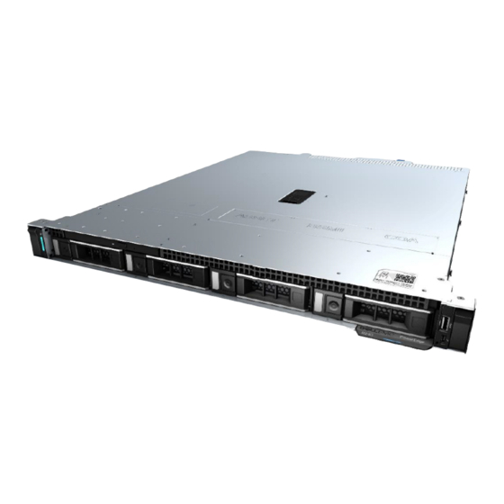
Dell EMC PowerEdge R240 system overview The Dell EMC PowerEdge R240 system is a 1U server that supports: • One Intel Xeon Scalable processor • Four DIMM slots • Cabled AC power supply unit • Up to four 3.5-inch SAS, SATA drives or SSDs, or four 3.5-inch cabled drives, or two 3.5-inch cabled drives. -
Page 9: Control Panels
LED functionality is not supported on cabled disk drive configuration. For more information about the ports, see the Technical Specifications section. Control panels Left control panel Figure 3. Left control panel view System health and system ID indicator Dell EMC PowerEdge R240 system overview... -
Page 10: Rear View Of The System
PSU Built-in Self Test (BIST) button System identification button System status indicator cable port (CMA) USB 3.0 ports (2) iDRAC dedicated NIC port VGA port For more information about the ports and connectors, see the Technical Specifications section. Dell EMC PowerEdge R240 system overview... -
Page 11: Inside The System
Figure 6. Inside the system - 4 x 3.5-inch drive system Optical drive Intrusion switch Cabled AC power supply unit Expansion card riser Processor and heat sink Memory module sockets System board Fan (4) Drive backplane Dell EMC PowerEdge R240 system overview... -
Page 12: Locating The Information Tag Of Your System
Tag by pulling out the information tag located on the front of the system. Alternatively, the information may be on the Mini Enterprise Service Tag (MEST) label on the chassis, on the rear of the system. This information is used by Dell to route support calls to the appropriate personnel. Dell EMC PowerEdge R240 system overview... - Page 13 Figure 8. Locating Service Tag of your system Information tag (front view) Information tag (back view) OpenManage Mobile (OMM) label iDRAC MAC address and iDRAC secure password label Service Tag, Express Service Code, QRL label Dell EMC PowerEdge R240 system overview...
-
Page 14: Initial System Setup And Configuration
Initial system setup and configuration Setting up your system Perform the following steps to set up your system: Unpack the system. Install the system into the rack. For more information about installing the system into the rack, see the Rail Installation Guide at Dell.com/poweredgemanuals. -
Page 15: Log In To Idrac
Ensure that you change the default user name and password after setting up the iDRAC IP address. NOTE: The Intel Quick Assist Technology (QAT) on the Dell EMC PowerEdge R240 is supported with chipset integration and is enabled through an optional license. The license files are enabled on the sleds through iDRAC. -
Page 16: Downloading Drivers And Firmware
Using iDRAC virtual media Dell.com/idracmanuals Downloading drivers and firmware Dell EMC recommends that you download and install the latest BIOS, drivers, and systems management firmware on your system. Prerequisite Ensure that you clear the web browser cache before downloading the drivers and firmware. -
Page 17: Pre-Operating System Management Applications
Pre-operating system management applications You can manage basic settings and features of a system without booting to the operating system by using the system firmware. Topics: • Options to manage the pre-operating system applications • System Setup • Dell Lifecycle Controller •... -
Page 18: System Setup Details
System Setup details The System Setup Main Menu screen details are explained as follows: Option Description System BIOS Enables you to configure BIOS settings. iDRAC Settings Enables you to configure the iDRAC settings. The iDRAC settings utility is an interface to set up and configure the iDRAC parameters by using UEFI (Unified Extensible Firmware Interface). - Page 19 Option Description Legacy network settings are managed from the Device Settings menu. Integrated Devices Specifies options to manage integrated device controllers and ports, specifies related features and options. Serial Specifies options to manage the serial ports, its related features and options. Communication System Profile Specifies options to change the processor power management settings, memory frequency.
- Page 20 Option Description System Specifies the contact information of the system manufacturer. Manufacturer Contact Information System CPLD Specifies the current version of the system complex programmable logic device (CPLD) firmware. Version UEFI Compliance Specifies the UEFI compliance level of the system firmware. Version Memory Settings You can use the Memory Settings screen to view all the memory settings and enable or disable specific memory functions, such as system...
- Page 21 Option Description Current State of Specifies the current state of the memory operating mode. Memory Operating Mode Processor Settings You can use the Processor Settings screen to view the processor settings, and perform specific functions such as enabling virtualization technology, hardware prefetcher, and logical processor idling. Viewing Processor Settings To view the Processor Settings screen, perform the following steps: Power on, or restart your system.
- Page 22 Option Description Processor 1 The following settings are displayed for each processor installed in the system: Option Description Family-Model- Specifies the family, model, and stepping of the processor as defined by Intel. Stepping Brand Specifies the brand name. Level 2 Cache Specifies the total L2 cache.
- Page 23 Option Description Option Description Drive Type Specifies the type of drive attached to the SATA port. Capacity Specifies the total capacity of the hard drive. This field is undefined for removable media devices such as optical drives. Port B Sets the drive type of the selected device. When the Embedded SATA setting is AHCI Mode, BIOS support is always enabled.
- Page 24 Option Description Option Description Model Specifies the drive model of the selected device. Drive Type Specifies the type of drive attached to the SATA port. Capacity Specifies the total capacity of the hard drive. This field is undefined for removable media devices such as optical drives.
- Page 25 Option Description Hard-Disk Failover Specifies the drive that is booted in the event of a drive failure. The devices are selected in the Hard-Disk Drive Sequence on the Boot Option Setting menu. When this option is set to Disabled, only the first drive in the list is attempted to boot.
- Page 26 UEFI iSCSI Settings You can use the iSCSI Settings screen to modify iSCSI device settings. The iSCSI Settings option is available only in the UEFI boot mode. BIOS does not control network settings in the BIOS boot mode. For the BIOS boot mode, the option ROM of the network controller handles the network settings.
- Page 27 On the System BIOS screen, click Integrated Devices. Integrated Devices details The Integrated Devices screen details are explained as follows: Option Description User Accessible Configures the user accessible USB ports. Selecting Only Back Ports On disables the front USB ports; selecting USB Ports All Ports Off disables all front and back USB ports;...
- Page 28 Option Description Table 3. Slot Disablement Option Description Enables or disables or only the boot driver is disabled Slot 1 for the PCIe slot 1. This option is set to Enabled by default. Enables or disables or only the boot driver is disabled Slot 2 for the PCIe slot 2.
- Page 29 Option Description NOTE: Only Serial Device 2 can be used for Serial Over LAN (SOL). To use console redirection by SOL, configure the same port address for console redirection and the serial device. NOTE: Every time the system boots, the BIOS syncs the serial MUX setting saved in iDRAC. The serial MUX setting can independently be changed in iDRAC.
- Page 30 Option Description C States Enables or disables the processor to operate in all available power states. This option is set to Enabled by default. Memory Refresh Sets the memory refresh rate to either 1x or 2x. This option is set to 1x by default. Rate Uncore Frequency Enables you to select the Processor Uncore Frequency option.
- Page 31 Option Description System Password Sets the system password. This option is set to Enabled by default and is read-only if the password jumper is not installed in the system. Setup Password Sets the setup password. This option is read-only if the password jumper is not installed in the system. Password Status Locks the system password.
- Page 32 Option Description Secure Boot Policy When Secure Boot policy is set to Standard, the BIOS uses the system manufacturer’s key and certificates to authenticate pre-boot images. When Secure Boot policy is set to Custom, the BIOS uses the user-defined key and certificates.
- Page 33 Use the following guidelines to assign the system password: • A password can have up to 32 characters. • The password can contain the numbers 0 through 9. • Only the following special characters are allowed: space, (”), (+), (,), (-), (.), (/), (;), ([), (\), (]), (`). A message prompts you to reenter the system password.
- Page 34 Operating with setup password enabled If Setup Password is set to Enabled, type the correct setup password before modifying the system setup options. If you do not type the correct password in three attempts, the system displays the following message: Invalid Password! Number of unsuccessful password attempts: <x>...
- Page 35 Option Description NOTE: RAID configurations and NVMe cards not are included as BIOS does not have the ability to distinguish between individual drives in those configurations. Redundant OS NOTE: This option is disabled if Redundant OS Location is set to None. State When set to Visible, the backup disk is visible to the boot list and OS.
-
Page 36: Idrac Settings Utility
Option Description Load Legacy Video Enables you to determine whether the system BIOS loads the legacy video (INT 10H) option ROM from the video Option ROM controller. Selecting Enabled in the operating system does not support UEFI video output standards. This field is available only for UEFI boot mode. -
Page 37: Boot Manager
Boot Manager The Boot Manager screen enables you to select boot options and diagnostic utilities. Viewing Boot Manager About this task To enter Boot Manager: Steps Power on, or restart your system. Press F11 when you see the following message: F11 = Boot Manager If your operating system begins to load before you press F11, allow the system to complete the booting, and then restart your system and try again. - Page 38 To access the PXE boot option, boot the system and then press F12 during POST instead of using standard Boot Sequence from BIOS Setup. It does not pull any menu or allows managing of network devices. Pre-operating system management applications...
-
Page 39: Installing And Removing System Components
Installing and removing system components Safety instructions WARNING: Whenever you need to lift the system, get others to assist you. To avoid injury, do not attempt to lift the system by yourself. WARNING: Opening or removing the system cover while the system is powered on may expose you to a risk of electric shock. CAUTION: Do not operate the system without the cover for a duration exceeding five minutes. -
Page 40: Recommended Tools
Recommended tools You need the following tools to perform the removal and installation procedures: • Key to the bezel lock The key is required only if your system includes a bezel. • Phillips #1 screwdriver • Phillips #2 screwdriver • Torx #T15 screwdriver •... -
Page 41: Installing The Front Bezel
Figure 9. Removing the front bezel Next step Replace the bezel. Installing the front bezel Prerequisites Follow the safety guidelines listed in the Safety instructions. Locate and remove the bezel key. NOTE: The bezel key is part of the bezel package. Steps Align and insert the tabs on the right end of the bezel into the slots on the system. -
Page 42: System Cover
Figure 10. Installing the front bezel System cover Removing the system cover Prerequisites Follow the safety guidelines listed in the Safety instructions. Disconnect the system from the electrical outlet and disconnect the peripherals. If applicable, remove the system from the rack. Rail Installation Guide at Dell.com/poweredgemanuals. -
Page 43: Installing The System Cover
Figure 11. Removing the system cover Installing the system cover Prerequisites Follow the safety guidelines listed in the Safety instructions. Power off the system, including all attached peripherals. Disconnect the system from the electrical outlet, and disconnect the peripherals. If applicable, remove the system from the rack. Rail Installation Guide at Dell.com/poweredgemanuals. -
Page 44: Air Shroud
Figure 12. Installing the system cover Next step Follow the procedure listed in the After working inside your system. Air shroud Removing the air shroud Prerequisites CAUTION: Never operate your system with the air shroud removed. The system may get overheated, resulting in shutdown of the system and loss of data. -
Page 45: Installing The Air Shroud
Figure 13. Removing the air shroud Next step Replace the air shroud. Installing the air shroud Prerequisite Follow the safety guidelines listed in Safety instructions. Follow the procedure listed in Before working inside your system. NOTE: Route the cable properly to prevent the cable from being pinched or crimped. Steps Align the tab on the air shroud with the slot on the system. -
Page 46: Cooling Fans
Cooling fans Removing the cooling fan blank Prerequisites Follow the safety guidelines listed in Safety instructions. Follow the procedure listed in the Before working inside your system. Steps Press the release tabs and push the fan blank out to disengage it from the fan cage. Lift the fan blank out of the fan cage. -
Page 47: Removing A Cooling Fan
Figure 16. Installing the fan blank Next step Follow the procedure listed in the After working inside your system. Removing a cooling fan Prerequisites WARNING: Opening or removing the system cover when the system is on may expose you to a risk of electric shock. Exercise utmost care while removing or installing fans. -
Page 48: Installing A Cooling Fan
Figure 17. Removing a cooling fan Next step Replace the cooling fan blank install the cooling fan. Installing a cooling fan Prerequisites Follow the safety guidelines listed in the Safety instructions. Follow the procedure listed in Before working inside your system.. -
Page 49: Drives
Figure 18. Installing a fan Next step Follow the procedure listed in the After working inside your system. Drives Removing a drive blank Prerequisites Follow the safety guidelines listed in the Safety instructions. Remove the front bezel. CAUTION: To maintain proper system cooling, drive blanks must be installed in all empty drive slots. CAUTION: Mixing drive blanks from previous generations of PowerEdge servers is not supported. -
Page 50: Installing A Drive Blank
Installing a drive blank Prerequisites Follow the safety guidelines listed in the Safety instructions. Remove the front bezel. CAUTION: To maintain proper system cooling, drive blanks must be installed in all empty drive slots. CAUTION: Mixing drive blanks from previous generations of PowerEdge servers is not supported. Step Insert the drive blank into the drive slot, and push the blank until the release button clicks into place. -
Page 51: Installing The Hot-Swappable Drive
Figure 21. Removing a hot-swappable drive Next step Replace the drive or install a drive blank. Installing the hot-swappable drive Prerequisites CAUTION: Before removing or installing a drive while the system is running, see the documentation for the storage controller card to ensure that the host adapter is configured correctly to support drive removal and insertion. -
Page 52: Removing The Drive From The Drive Carrier
Close the drive release handle to lock the drive in place. Figure 22. Installing the hot-swappable drive Next step Replace the front bezel. Removing the drive from the drive carrier Prerequisites Follow the safety guidelines listed in Safety instructions. If installed, remove the front bezel. -
Page 53: Installing The Drive Into The Drive Carrier
Figure 23. Removing the drive from the drive carrier Installing the drive into the drive carrier Prerequisites Follow the safety guidelines listed in Safety instructions. If installed, remove the front bezel. Remove the drive blank. Steps Insert the drive into the drive carrier with the drive connector facing towards the rear of the carrier. Align the screw holes on the drive with the screws holes on the drive carrier. -
Page 54: Removing A 2.5-Inch Drive From A 3.5-Inch Drive Adapter
Figure 24. Installing a drive into the drive carrier Next steps Install the drive carrier. If removed, install the front bezel. Removing a 2.5-inch drive from a 3.5-inch drive adapter Steps Using a Phillips #1 screwdriver, remove the screws from the side of the 3.5-inch drive adapter. Remove the drive from the 3.5-inch drive adapter. -
Page 55: Installing A 2.5-Inch Drive Into A 3.5-Inch Drive Adapter
Figure 25. Removing a 2.5-inch drive from a 3.5-inch drive adapter Next step Install a 2.5-inch drive into the 3.5-inch drive adapter. Installing a 2.5-inch drive into a 3.5-inch drive adapter Steps Align the screw holes on the 2.5-inch drive with the screw holes on the 3.5-inch drive adapter. Using a Phillips #1 screwdriver, install the screws to secure the drive to the 3.5-inch drive adapter. -
Page 56: Removing A 3.5-Inch Drive Adapter From A 3.5-Inch Drive Carrier
Figure 26. Installing a 2.5-inch drive into a 3.5-inch drive adapter Next step Follow the procedure listed in the After working inside your system. Removing a 3.5-inch drive adapter from a 3.5-inch drive carrier Prerequisites Follow the safety guidelines listed in the Safety instructions. -
Page 57: Installing A 3.5-Inch Adapter Into A 3.5-Inch Drive Carrier
Figure 27. Removing a 3.5-inch drive adapter from a 3.5-inch drive carrier Next step Replace a 3.5-inch adapter into a 3.5-inch drive carrier. Installing a 3.5-inch adapter into a 3.5-inch drive carrier Prerequisite Follow the safety guidelines listed in the Safety instructions. -
Page 58: Removing A Cabled Drive
Figure 28. Installing a 3.5-inch drive adapter into the 3.5-inch drive carrier Next steps Replace a 3.5-inch drive carrier. Follow the procedure listed in After working inside your system. Removing a cabled drive Prerequisites Follow the safety guidelines listed in the Safety instructions. -
Page 59: Installing A Cabled Drive
Figure 29. Removing a cabled drive Next step Install the drive into the drive carrier. Installing a cabled drive Prerequisites Follow the safety guidelines listed in the Safety instructions. Follow the procedure listed in the Before working inside your system. CAUTION: Mixing drive carriers from other generations of PowerEdge servers is not supported. -
Page 60: Removing The Cabled Drive From The Drive Carrier
Figure 30. Installing a cabled drive Next step Follow the procedure listed in the After working inside your system. Removing the cabled drive from the drive carrier Prerequisites Follow the safety guidelines listed in the Safety instructions. Follow the procedure listed in the Before working inside your system. -
Page 61: Installing A Cabled Drive Into The Drive Carrier
Figure 31. Removing the cabled drive from the drive carrier Next step Install the drive into the drive carrier. Installing a cabled drive into the drive carrier Prerequisites Follow the safety guidelines listed in the Safety instructions. Follow the procedure listed in the Before working inside your system. -
Page 62: Intrusion Switch
Figure 32. Installing a cabled drive into the drive carrier Next steps Enter System Setup and ensure that the controller of the drive is enabled. Exit System Setup and reboot the system. Install any software required for the drive operation as described in the documentation for the drive. Follow the procedure listed in the After working inside your system. -
Page 63: Installing The Intrusion Switch
Figure 33. Removing the intrusion switch Next step Replace the intrusion switch. Installing the intrusion switch Prerequisites Follow the safety guidelines listed in the Safety instructions. Follow the procedure listed in the Before working inside your system. Steps Align and slide the intrusion switch into the slot in the system. Route the intrusion switch cable through the cable routing clips. -
Page 64: System Memory Guidelines
System memory guidelines Your system contains 4 memory sockets organized into two channels. In each channel, the 1st socket is marked white and the 2nd socket black. Figure 35. Memory socket locations Memory channels are organized as follows: Table 4. Memory channels Memory socket locations on the system board Processor 1 Channel 0: Memory slots A1 and A3... -
Page 65: General Memory Module Installation Guidelines
Table 5. Memory population DIMM Type DIMMs Populated/ Operating Frequency (in MT/s) Maximum DIMM Rank/Channel Voltage Channel UDIMM 2666 Dual rank or Single rank 1.2 V General memory module installation guidelines To ensure optimal performance of your system, observe the following general guidelines when configuring your system memory. If your system's memory configurations fail to observe these guidelines, your system might not boot, stop responding during memory configuration, or operate with reduced memory. -
Page 66: Removing A Memory Module
Removing a memory module Prerequisites WARNING: Allow the memory modules to cool after you power off the system. Follow the safety guidelines listed in the Safety instructions. Follow the procedure listed in the Before working inside your system. Remove the air shroud. -
Page 67: Expansion Cards And Expansion Card Risers
A System Event Log (SEL) event is logged if an expansion card riser is not supported or missing. It does not prevent your Troubleshooting expansion cards section in system from turning on. However, if a F1/F2 pause occurs with an error message, see Dell EMC PowerEdge Servers Troubleshooting Guide at Dell.com/poweredgemanuals. Installing and removing system components... -
Page 68: Expansion Card Installation Guidelines
Expansion card installation guidelines To ensure proper cooling and mechanical fit, the following table provides guidelines for installing expansion cards. The expansion cards with the highest priority must be installed first using the slot priority indicated. All the other expansion cards should be installed in the card priority and slot priority order. -
Page 69: Removing The Expansion Card Riser
Card type Slot priority Maximum number of cards supported CRD, NTWK, PCIE, QP, 1G, BCOM, LP, V2 CRD, NTWK, PCIE, 1GB, QP, INTEL, V3 CRD, NTWK, PCIE, 1GB, QP, INT, LP, V3 CRD, NTWK, DP, BCOM, 1G CRD, NTWK, DP, BCOM, 1G, LP CRD, NTWK, PCIE, 1GB, DP, INTEL, V3 CRD, NTWK, PCIE, 1GB, DP, INT, LP, V3 Removing the expansion card riser... -
Page 70: Installing The Expansion Card Riser
Figure 40. Installing the expansion card riser filler Next step If applicable, replace the expansion card riser. Installing the expansion card riser Prerequisites Follow the safety guidelines listed in the Safety instructions. Follow the procedure listed in the Before working inside your system. - Page 71 Figure 41. Removing the expansion card riser filler Holding the blue touch points on the expansion card riser, align the expansion card with the connector on the system board. Lower the expansion card riser into place until the expansion card riser is fully seated with the connector on the system board. Close the blue expansion card retention latch.
-
Page 72: Removing Expansion Card From The Expansion Card Riser
Removing expansion card from the expansion card riser Prerequisites Follow the safety guidelines listed in the Safety instructions. Follow the procedure listed in the Before working inside your system. Remove the air shroud. If installed, remove the expansion card riser. If applicable, disconnect the cables from the expansion card. -
Page 73: Installing Expansion Card Into The Expansion Card Riser
Figure 44. Installing the expansion card filler Next step Install the expansion card into the expansion card riser. Installing expansion card into the expansion card riser Prerequisites Follow the safety guidelines listed in the Safety instructions. Follow the procedure listed in the Before working inside your system. - Page 74 Figure 45. Removing expansion card filler Holding the card by its edges, insert the expansion card to connect it to the connector on the riser. Figure 46. Installing expansion card into the expansion card riser Next steps Replace the expansion card riser.
-
Page 75: M.2 Ssd Module
M.2 SSD module Removing the M.2 SSD module Prerequisites Follow the safety guidelines listed in Safety instructions. Follow the procedure listed in Before working inside your system. Remove the air shroud. Remove the BOSS card. NOTE: The procedure to remove the BOSS card is similar to removing an expansion card. Steps Using the Phillips #1 screwdriver, remove the screws securing the M.2 SSD module to the BOSS card. -
Page 76: System Battery
Remove the BOSS card. NOTE: The procedure to remove the BOSS card is similar to the removing an expansion card. Steps Align the M.2 SSD module at an angle with the BOSS card connector. Insert the M.2 SSD module until it is firmly seated in the BOSS card connector. Using the Phillips #1 screwdriver, secure the M.2 SSD module on the BOSS card with the screw. - Page 77 Steps To remove the battery: Push the battery holder clip. NOTE: Ensure that you do not push the battery holder clip more than 3.2 millimeters, It may damage the battery holder. b Push the battery toward the positive side of the battery until the battery disengages from the connector. Lift the battery away from the system.
-
Page 78: Optional Internal Usb Memory Key
Figure 50. Installing system battery Next steps Install the expansion card riser. Install the air shroud. Follow the procedure listed in the After working inside your system. Confirm that the battery is operating properly, by performing the following steps: Enter the System Setup, while booting, by pressing F2. Enter the correct time and date in the System Setup Time and Date fields. -
Page 79: Replacing The Optional Internal Usb Memory Key
Replacing the optional internal USB memory key Prerequisites CAUTION: To avoid interference with other components in the server, the maximum permissible dimensions of the USB memory key: 15.9 mm width x 57.15 mm length x 7.9 mm height. Follow the safety guidelines listed in the Safety instructions. -
Page 80: Installing The Optional Optical Drive
Figure 51. Removing the optional optical drive Next step If applicable, replace the optical drive. Installing the optional optical drive Prerequisites The procedure for installing an optical drive and optical drive blank. Follow the safety guidelines listed in the Safety instructions. -
Page 81: Processor And Heat Sink
Figure 52. Installing the optional optical drive Next steps Install the front bezel. Follow the procedure listed in the After working inside your system. Processor and heat sink Removing the heat sink Prerequisites WARNING: The heat sink may be hot to touch for some time after the system is powered down. Allow the heat sink to cool before removing it. -
Page 82: Removing The Processor
Figure 53. Removing the heat sink Next step If you are removing a faulty heat sink, replace the heat sink, if not, remove the processor. Removing the processor Prerequisites Follow the safety guidelines listed in the Safety instructions. Follow the procedure listed in the Before working inside your system. -
Page 83: Installing The Processor
Figure 54. Removing the processor Next steps Install the processor. Install the heat sink. Installing the processor Prerequisites Follow the safety guidelines listed in the Safety instructions. Follow the procedure listed in the Before working inside your system. Remove the air shroud. -
Page 84: Installing The Heat Sink
NOTE: Ensure that you install the heat sink after you install the processor. The heat sink is necessary to maintain proper thermal conditions. Follow the procedure listed in the After working inside your system. Installing the heat sink Prerequisites Follow the safety guidelines listed in the Safety instructions. -
Page 85: Optional Idsdm Or Vflash Module
Optional IDSDM or vFlash module The IDSDM or vFlash module combines the IDSDM and/or vFlash features into a single module. NOTE: The write-protect switch is on the IDSDM or vFlash module. Removing the optional IDSDM or vFlash card Prerequisites Follow the safety guidelines listed in Safety instructions. -
Page 86: Removing The Microsd Card
Figure 57. Installing the optional IDSDM or vFlash card Next steps Install the MicroSD cards. NOTE: Reinstall the MicroSD cards into the same slots that are based on the labels you had marked on the cards during removal. Install the air shroud. -
Page 87: Installing The Microsd Card
Figure 58. Removing the MicroSD card Next step Replace the MicroSD cards. Installing the MicroSD card Prerequisites Follow the safety guidelines listed in the Safety instructions. Follow the procedure listed in the Before working inside your system. Remove the air shroud. Remove the IDSDM or vFlash module. -
Page 88: Drive Backplane
Follow the procedure listed in the After working inside your system. Drive backplane Drive backplane The PowerEdge R240 system supports 3.5-inch (x4) SAS/SATA backplane. Figure 60. 3.5-inch (x4) SAS/SATA backplane Release tab (2) Backplane SAS A0 connector (BP_SAS_A) Backplane Power A connector (BP_PWR_A) -
Page 89: Removing The Drive Backplane
Removing the drive backplane Prerequisites CAUTION: You must note the number of each drive and temporarily label them before removal so that you can replace them in the same drive slots. Follow the safety guidelines listed in the Safety instructions. Follow the procedure listed in the Before working inside your system. - Page 90 Follow the procedure listed in the Before working inside your system. Remove the drives. NOTE: To avoid damaging the backplane, ensure to move the control panel cables from the cable routing clips before removing the backplane. NOTE: Route the cable properly when you replace it to prevent the cable from being pinched or crimped. Steps Align the slots on the backplane with the hooks on the system.
-
Page 91: Cable Routing
Cable routing Figure 63. Cable routing - 4 x 3.5-inch drive backplane with PERC Figure 64. Cable routing - 4 x 3.5-inch drive backplane with SATA Installing and removing system components... - Page 92 Figure 65. Cable routing - 4 x 3.5-inch cabled drive with PERC Figure 66. Cable routing - 4 x 3.5-inch cabled drive with SATA Installing and removing system components...
-
Page 93: Power Supply Unit
Figure 67. Cable routing - 2 x 3.5-inch cabled drive with PERC Figure 68. Cable routing - 2 x 3.5-inch cabled drive with SATA Power supply unit NOTE: For more information, see the Technical specifications section. Removing a cabled power supply unit Prerequisites Follow the safety guidelines listed in the Safety... -
Page 94: Installing A Cabled Power Supply Unit
Remove the air shroud. Disconnect the system from the electrical outlet. Disconnect all the cables connected from the PSU to the system board and the backplane. If applicable, remove the expansion card riser. Steps Using a Phillips #2 screwdriver, remove the screw securing the PSU to the system. Slide the PSU out of the PSU bay in the chassis. -
Page 95: System Board
Figure 70. Installing a cabled power supply unit Next steps Connect the PSU cables to the connectors on the system board and the backplane. If applicable, install the expansion card riser. Install the air shroud. Follow the procedure listed in the After working inside your system. - Page 96 Internal Dual SD module, if installed Disconnect all the cables that are connected to the system board. CAUTION: Take care not to damage the system identification button while removing the system board from the system. CAUTION: Do not lift the system board by holding a memory module, processor, or other components. Steps Using a Phillips #2 screwdriver, remove the screws securing the system board to the chassis.
-
Page 97: Installing The System Board
Figure 72. Removing the system board Next step Install the system board. Installing the system board Prerequisites Follow the safety guidelines listed in the Safety instructions. Follow the procedure listed in the Before working inside your system. If you are replacing the system board, remove all the components listed in the Removing the system board section. - Page 98 Figure 73. Installing the system board Using a Phillips #2 screwdriver, tighten the screws that secure the system board to the chassis. Next steps Replace the following: Trusted Platform Module (TPM) NOTE: The TPM must be replaced only while installing a new system board. NOTE: The TPM plug-in module is attached to the system board and cannot be removed.
-
Page 99: Restoring The System Using Easy Restore
Restoring the system using Easy Restore The easy restore feature enables you to restore your service tag, license, UEFI configuration, and the system configuration data after replacing the system board. All data is backed up in a backup flash device automatically. If BIOS detects a new system board, and the service tag in the backup flash device, BIOS prompts the user to restore the backup information. -
Page 100: Initializing Tpm For Bitlocker Users
Removing the TPM Locate the TPM connector on the system board. Press to hold the module down and remove the screw using the security Torx 8-bit shipped with the TPM module. Slide the TPM module out from its connector. Push the plastic rivet away from the TPM connector and rotate it 90° counterclockwise to release it from the system board. Pull the plastic rivet out of its slot on the system board. -
Page 101: Initializing The Tpm 1.2 For Txt Users
Initializing the TPM 1.2 for TXT users While booting your system, press F2 to enter System Setup. On the System Setup Main Menu screen, click System BIOS > System Security Settings. From the TPM Security option, select On with Preboot Measurements. From the TPM Command option, select Activate. -
Page 102: Installing The Left Control Panel
Figure 75. Removing the left control panel Next step Install the left control panel. Installing the left control panel Prerequisites Follow the safety guidelines listed in the Safety instructions. Follow the procedure listed in the Before working inside your system. Remove the front bezel. -
Page 103: Removing The Right Control Panel
Figure 76. Installing the left control panel Next step Follow the procedure listed in the After working inside your system. Removing the right control panel Prerequisites Follow the safety guidelines listed in the Safety instructions. Follow the procedure listed in the Before working inside your system. -
Page 104: Installing The Right Control Panel
Figure 77. Removing the right control panel Next step Install the right control panel. Installing the right control panel Prerequisites Follow the safety guidelines listed in the Safety instructions. Follow the procedure listed in the Before working inside your system. Remove the front bezel. - Page 105 Figure 78. Installing the right control panel Next step Follow the procedure listed in the After working inside your system. Installing and removing system components...
-
Page 106: Jumpers And Connectors
Jumpers and connectors This topic provides specific information about the jumpers. It also provides some basic information about jumpers and switches and describes the connectors on the various boards in the system. Jumpers on the system board help to disable the system and setup passwords. -
Page 107: System Board Connectors
System board connectors Figure 79. System board connectors Table 9. System board connectors and descriptions Item Connector Description FAN 1 Fan 1 cable connector BP_SIG Backplane signal cable connector NVRAM_CLR Clear NVRAM PWRD_EN Reset BIOS password jumper RISER_PCIE PERC PCIe x8 socket INT_USB_3.0 Internal USB 3.0 connector OMNIVU_LED1... -
Page 108: System Board Jumper Settings
Item Connector Description Power cable connector 2 A1, A2, A3, A4 Memory module sockets SATA0-3 SATA signal cable connector SATA_ODD-HDD4 SATA connector—Optical drive SATA connector Power cable connector 1 FAN4 Fan 4 cable connector FAN3 Fan 3 cable connector FAN2 Fan 2 cable connector TPM connector LEFT_LED... - Page 109 Steps Power off the system, including any attached peripherals, and disconnect the system from the electrical outlet. Remove the system cover. Move the jumper on the system board jumper from pins 2 and 4 to pins 4 and 6. Install the system cover. The existing passwords are not disabled (erased) until the system boots with the jumper on pins 4 and 6.
-
Page 110: Technical Specifications
Technical specifications The technical and environmental specifications of your system are outlined in this section. Topics: • Chassis dimensions • System weight • Processor specifications • PSU specifications • Cooling fans specifications • System battery specifications • Expansion card riser specifications •... -
Page 111: Chassis Dimensions
Chassis dimensions Figure 80. Chassis dimensions Table 11. Dell EMC PowerEdge R240 chassis dimensions With bezel: 35.64 482.0 mm 434.0 mm 42.8 mm 534.496 mm 573.596 mm mm (1.4 inches) (18.97 inches) (17.08 inches) (1.68 inches) (21.04 inches) (22.58 inches) Without bezel: 22.0... -
Page 112: Processor Specifications
= 4 installed System battery specifications The Dell EMC PowerEdge R240 system supports CR 2032 3.0-V lithium coin cell system battery. Expansion card riser specifications The Dell EMC PowerEdge R240 system supports up to two PCI express (PCIe) generation 3. -
Page 113: Memory Specifications
PCIe Low-profile Half-length Slot 2 x16 PCIe Low-profile/Full-height Half-length Memory specifications The PowerEdge R240 system supports the following memory specifications for optimized operation. Table 17. Memory specifications DIMM type DIMM rank DIMM capacity Minimum RAM Maximum RAM 8 GB... -
Page 114: Optical Drives
The Dell EMC PowerEdge R240 system supports up to two 10/100/1000 Mbps Network Interface Controller (NIC) ports that are located on the back panel. Serial connector specifications The Dell EMC PowerEdge R240 system supports one serial connector on the back panel, which is a 9-pin connector, Data Terminal Equipment (DTE), 16550-compliant. VGA ports specifications The Dell EMC PowerEdge R240 system supports DB-15 VGA connector. -
Page 115: Idsdm Module
Use Dell EMC branded microSD cards that are associated with the IDSDM or vFlash configured systems. Video specifications The Dell EMC PowerEdge R240 system supports integrated Matrox G200 graphics controller with 16 MB of video frame buffer. Table 23. Supported video resolution options... - Page 116 Temperature Specifications Fresh air For information about fresh air, see the Expanded operating temperature section. Maximum temperature gradient (operating and 20°C/h (36°F/h) storage) Table 25. Relative humidity specifications Relative humidity Specifications Storage 5% to 95% RH with 33°C (91°F) maximum dew point. Atmosphere must be noncondensing at all times.
-
Page 117: Standard Operating Temperature
Standard operating temperature Table 30. Standard operating temperature specifications Standard operating temperature Specifications Continuous operation (for altitude less than 950 m or 3117 10–35°C (50–95°F) with no direct sunlight on the equipment. Expanded operating temperature Table 31. Expanded operating temperature specifications Expanded operating temperature Specifications Continuous operation... -
Page 118: Particulate And Gaseous Contamination Specifications
Particulate and gaseous contamination specifications The following table defines the limitations that help avoid any damages to the IT equipment and/or, or both failure from particulate and gaseous contamination. If the levels of particulate or gaseous pollution exceed the specified limitations and results in equipment damage or failure, you must rectify the environmental conditions. -
Page 119: System Diagnostics And Indicator Codes
System diagnostics and indicator codes The diagnostic indicators on the system front panel display system status during system startup. Topics: • System health and system ID indicator codes • iDRAC Direct LED indicator codes • NIC indicator codes • Non-redundant cabled power supply unit indicator codes •... -
Page 120: Idrac Direct Led Indicator Codes
Table 34. System health and system ID indicator codes System health and system ID indicator Condition code Solid blue Indicates that the system is turned on, system is healthy, and system ID mode is not active. Press the system health and system ID button to switch to system ID mode. Blinking blue Indicates that the system ID mode is active. -
Page 121: Non-Redundant Cabled Power Supply Unit Indicator Codes
Table 36. NIC indicator codes Status Condition Link and activity indicators are off. The NIC is not connected to the network. Link indicator is green, and activity indicator is blinking The NIC is connected to a valid network at its maximum port speed, and green. -
Page 122: Drive Indicator Codes
Drive indicator codes The LEDs on the drive carrier indicates the state of each drive. Each drive carrier in your system has two LEDs: an activity LED (green) and a status LED (bicolor, green/amber). The activity LED flashes whenever the drive is accessed. Figure 84. - Page 123 • Run tests automatically or in an interactive mode • Repeat tests • Display or save test results • Run thorough tests to introduce additional test options to provide extra information about the failed device(s) • View status messages that inform you if tests are completed successfully •...
-
Page 124: Getting Help
Accessing system information by using QRL You can use the Quick Resource Locator (QRL) located on the information tag in the front of the R240, to access the information about the Dell EMC PowerEdge R240. Prerequisites Ensure that your smartphone or tablet has the QR code scanner installed. -
Page 125: Quick Resource Locator For Dell Emc Poweredge R240 System
Receiving automated support with SupportAssist Dell EMC SupportAssist is an optional Dell EMC Services offering that automates technical support for your Dell EMC server, storage, and networking devices. By installing and setting up a SupportAssist application in your IT environment, you can receive the following benefits: •... -
Page 126: Documentation Resources
To view the document that is listed in the documentation resources table: • From the Dell EMC support site: Click the documentation link that is provided in the Location column in the table. Click the required product or product version. - Page 127 Dell OpenManage Essentials, see Essentials the Dell OpenManage Essentials User’s Guide. For information about installing and using Dell Dell.com/serviceabilitytools SupportAssist, see the Dell EMC SupportAssist Enterprise User’s Guide. For information about partner programs enterprise Dell.com/openmanagemanuals systems management, see the OpenManage Connections Enterprise Systems Management documents.
Need help?
Do you have a question about the PowerEdge R240 and is the answer not in the manual?
Questions and answers