Table of Contents
Advertisement
Quick Links
Advertisement
Table of Contents

Subscribe to Our Youtube Channel
Summary of Contents for RED RANGER MONSTRO 8K VV
- Page 1 RED RANGER OPERATION GUIDE MONSTRO 8K VV V7.2 RED.COM...
-
Page 2: Table Of Contents
Audio During Playback Power Operations Record Audio in Varispeed Mode Configure Your Camera CHAPTER 8: Timecode, Genlock, Multi- Camera Setup Shim the RED RANGER Shimmed PL Mount 38 Timecode Interchangeable OLPF System Genlock Use a Tripod or Monopod Master/Slave Operation... - Page 3 General Troubleshooting Error Messages APPENDIX A: Technical Specifications RED RANGER Technical Specifications APPENDIX B: Mechanical Drawings RED RANGER with V-Lock RED RANGER with Gold Mount APPENDIX C: Input/Output Connectors Record/Monitor Out Ports Communication Ports Audio Ports Power Ports APPENDIX D: Lens Mounts and Lenses...
-
Page 4: Disclaimer
RED RANGER OPERATION GUIDE DISCLAIMER TRANSLATION DISCLAIMER ® has made every effort to provide clear and accurate This document was originally prepared in English, and any translations information in this document, which is provided solely for the user’s are provided for convenience only. While reasonable efforts were information. - Page 5 RED RANGER OPERATION GUIDE EUROPEAN UNION COMPLIANCE STATEMENTS CAUTION: Exposure Radio Frequency Radiation. The device shall be used in such a RED declares that the radio equipment manner that the potential for human contact is described in this document comply with the minimized.
-
Page 6: Safety Instructions
RED RANGER OPERATION GUIDE Before installing or removing these items, you MUST turn off the SAFETY INSTRUCTIONS camera. Failure to do so may result in damage to the item or DO NOT use the camera or accessories near water. Avoid camera that is not covered under warranty. -
Page 7: Battery Storage And Handling
RED RANGER OPERATION GUIDE DO NOT disassemble or modify the battery. DO NOT overcharge batteries. Overcharging may increase internal temperature beyond the recommended limits and cause INDOOR USE ONLY: This device is designed for permanent damage to the battery. use indoors only. -
Page 8: Shipping Disclaimer
RED RANGER OPERATION GUIDE SHIPPING DISCLAIMER Shipment of Lithium Ion cells and batteries is subject to national and international shipping requirements. A Class 9 Certified shipper is required to transport these products within the United States. REDVOLT, REDVOLT-V, REDVOLT XL, and RED BRICK batteries are considered Dangerous Goods. -
Page 9: Chapter 1: Product Introduction
RED RANGER is an integrated Large Format 8K camera system offering an all-in-one system for top-tier production use. It features all of the benefits of the MONSTRO 8K VV sensor within a compact and less complex platform for filmmakers. Features like integrated I/O’s, 24V power out, shimmed PL Mount, and improved thermal performance offer unmatched versatility as well as peace of mind in challenging shooting environments. -
Page 10: R3D File Format And Redcode
RED RANGER OPERATION GUIDE R3D FILE FORMAT AND REDCODE ® All videos and frames are recorded to the R3D file format. The R3D file format was developed by RED to provide an efficient and manageable RAW video data format that promotes advanced post production editing capabilities. In the R3D file format, the digital image received from the sensor is formatted as a pixel-defect corrected (but in all other aspects unprocessed) 16-bit per pixel RAW data frame. -
Page 11: Post Production
RED RANGER OPERATION GUIDE POST PRODUCTION NOTE: Third-party applications may have limited compatibility with R3D files. Third-party developers must use the most recent R3D SDK to offer compatibility with the latest RED firmware. Many non- linear editing systems (NLEs) can open and edit RED footage. Each NLE version may have specific compatibility requirements, such as camera firmware version or camera type. -
Page 12: Hdrx And Magic Motion
RED RANGER OPERATION GUIDE HDRX AND MAGIC MOTION HDRX ® HDRX extends dynamic range up to six (6) stops by simultaneously capturing two (2) images of identical resolution and frame rate. The first image is a normally exposed track (A-track), while the second is an underexposed track (X- track) with an exposure value that reflects the additional stops of highlight protection. -
Page 13: Chapter 2: Camera System Components
NOTE: Availability of components listed in this chapter is subject to change at any time. RED RANGER CAMERA BODY This section describes the controls, buttons, and features on the RED RANGER camera body. For information on the input/output connectors, go to "Input/Output Connectors"... - Page 14 RED RANGER OPERATION GUIDE CAMERA BODY CONTROLS AND FEATURES CAMERA FRONT Figure: Camera Body Controls and Features # ITEM DESCRIPTION 1 Lens mount area Attach lens mount 2 Mic 1 Left audio channels: Ch1 and Ch3. Go to "Audio System" on page 143 3 Mic 2 Right audio channels: Ch2 and Ch4.
- Page 15 RED RANGER OPERATION GUIDE CAMERA TOP Figure: Camera Body Controls and Features # ITEM DESCRIPTION 7 Primary Mount a DSMC2 RED Touch LCD, LCD/EVF Adaptor A, or LCD/EVF Adaptor D EVF/LCD Port 8 Top Mount the DSMC2 Top Handle or DSMC2 Outrigger Handle. This is the only mounting option for the...
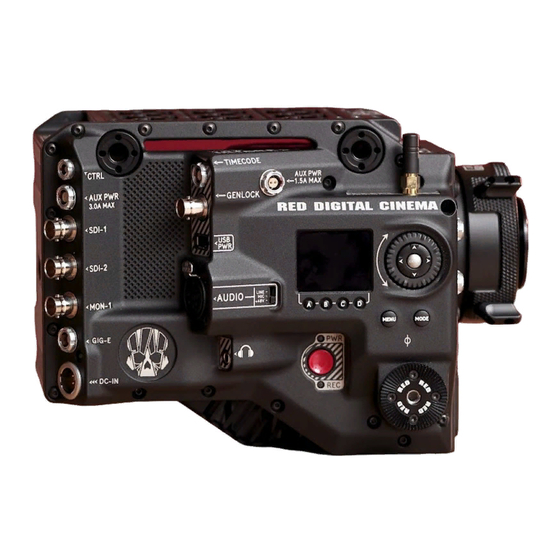
- Page 16 RED RANGER OPERATION GUIDE CAMERA LEFT Figure: Camera Body Controls and Features ITEM DESCRIPTION 10 PWR/REC button Fully press and hold the PWR/REC key for two (2) seconds to turn on/off. When the camera is on, fully press and then release the PWR/REC key to toggle record start/stop.
- Page 17 RED RANGER OPERATION GUIDE CAMERA RIGHT Figure: Camera Body Controls and Features ITEM DESCRIPTION 12 Focal plane marks Marks align with the sensor plane; pull focus from these marks. 15 Focus Hook Store the focus hook screw Screw Storage Location...
- Page 18 CAMERA BACK Figure: Camera Body Controls and Features ITEM DESCRIPTION 19 Battery Depending on the RED RANGER type, you can attach either a gold mount battery or a v-lock mount battery 20 Media mount Mount RED MINI-MAG media 21 Fan exhaust DO NOT block fan exhaust when the camera is on C O PYR I G HT ©...
- Page 19 RED RANGER OPERATION GUIDE CAMERA BOTTOM Figure: Camera Body Controls and Features ITEM LOCATION DESCRIPTION Fan exhaust Back/Bottom DO NOT block fan exhaust when the camera is on Mounting Points Bottom Mount plates, tripods, monopods, etc. C O PYR I G HT © 2 0 1 9 R ED.C O M , LLC...
- Page 20 CAMERA BODY LEDS LEFT SIDE LEDS Figure: RED RANGER LEDs, Right Side NOTE: When the camera is powered only by battery and not AC power, the Power Status LED (PWR) does not turn on. To check the battery charge level, press the button on the battery.
- Page 21 RED RANGER OPERATION GUIDE MEDIA BAY LEDS Figure: Media Bay LEDs # LED COLOR/FLASHING DESCRIPTION 1 Media Status LED (Back of media No media mounted bay) Green Preview; media mounted; > 10% of media space available Amber Record finalizing or playback mode...
-
Page 22: Red Mini-Mag System
RED RANGER OPERATION GUIDE RED MINI-MAG SYSTEM Figure: RED MINI-MAG (120GB) NOTE: For more information, see the DSMC Media Operation Guide, available at www.red.com/downloads. ® ® RED MINI-MAG SSDs deliver fast and reliable recording options for your camera. A RED STATION enables you to connect media to your computer for offloading and editing. -
Page 23: Power Components
RED RANGER OPERATION GUIDE POWER COMPONENTS The following RED batteries, battery chargers, and power cables are compatible with the RED RANGER: ITEM PART NUMBER NOTES REDVOLT-V 740-0043 For use with V-Lock RED BRICK 740-0002 For use with V-Lock RED RANGER AC Power 740-0048 Power adaptor for AC power;... -
Page 24: Displays And Electronic Viewfinders
730-0010 1. Approximate measurements. 2. Using this display with RED RANGER requires a DSMC2 LCD/EVF Adaptor A or DSMC2 LCD/EVF Adaptor D. 3. The DSMC2 Touch 7.0" Ultra-Brite LCD requires that your camera is on firmware v7.2 or later. C O PYR I G HT © 2 0 1 9 R ED.C O M , LLC... - Page 25 RED RANGER OPERATION GUIDE RED LCDS RED displays provide important camera parameters on the graphical user interface (GUI) and offer a variety of monitor viewing options. RED touchscreen displays enable you to use gestures to navigate menus and adjust camera parameters.
- Page 26 RED RANGER OPERATION GUIDE BOMB EVF FEATURES # FEATURE DESCRIPTION 1 EVF Custom digital video and power interconnection between the camera and RED EVF; Pinout not Connector published 2 EVF Tally When enabled, the LED illuminates red when recording; For more information, go to "Indicator"...
- Page 27 RED RANGER OPERATION GUIDE DSMC2 RED EVF The DSMC2 RED EVF (OLED) is a high definition electronic viewfinder designed as the ideal single-viewer monitoring solution. Featuring the latest OLED technology, this EVF provides an unmatched personal viewing experience with a 1080p OLED micro-display, and improved color accuracy with 30-bit RGB color represenation.
- Page 28 RED RANGER OPERATION GUIDE DSMC2 RED EVF FEATURES Figure: DSMC2 RED EVF # FEATURE DESCRIPTION 1 DSMC2 RED EVF The DSMC2 RED EVF Mount. Mount DO NOT overtighten the black tension ring on the EVF connector. The EVF is designed to allow rotation even when the tension ring is fully engaged.
-
Page 29: Lcd/Evf Adaptors
RED EVFs, fully compatible with the RED RANGER. The DSMC2 LCD/EVF Adaptor A converts the pogo connection on the RED RANGER to a 16-Pin 1B LCD/EVF port. The DSMC2 LCD/EVF Adaptor A is designed to attach to the primary (top) EVF/LCD port on the RED RANGER. - Page 30 Similar to the DSMC2 LCD/EVF Adaptor A, the DSMC2 LCD/EVF Adaptor D converts the pogo connection on the RED RANGER to a 16-Pin 1B LCD/EVF port. The DSMC2 LCD/EVF Adaptor D is designed to attach to the primary (top), or the secondary (side) EVF/LCD port on the RED RANGER.
-
Page 31: Camera Control Devices
RED RANGER OPERATION GUIDE CAMERA CONTROL DEVICES This section describes the camera control devices that offer Record Start/Stop buttons: ITEM PART NUMBER DSMC2 Top Handle 720-0035 DSMC2 Outrigger Handle 720-0044 DSMC2 TOP HANDLE Figure: DSMC2 Top Handle Ergonomic and intuitive, the DSMC2 Top Handle was engineered entirely around the most important action for any shooter—the record button. -
Page 32: Lens Mounts
RED RANGER OPERATION GUIDE LENS MOUNTS RED recommends only using the RED RANGER Shimmed PL Mount with the RED RANGER. Other RED lens mounts are mechanically compatible, but may cause focus accuracy issues. ITEM PART NUMBER RED RANGER Shimmed PL Mount... -
Page 33: Rails, Mounts, Tactical Gear, And Cables
RED RANGER OPERATION GUIDE RAILS, MOUNTS, TACTICAL GEAR, AND CABLES RED offers a wide variety of support gear, mounting platforms, cables, accessories, and other equipment. For more information, visit the RED Store at www.red.com/store. MAXIMUM SUPPORTED WEIGHTS The table below lists the maximum weight each handle can support in specific configurations. Damage to handles or other components of the camera system caused by using a handle to lift more than the specified weight is not covered under warranty. -
Page 34: Chapter 3: Basic Operations
RED RANGER OPERATION GUIDE CHAPTER 3: BASIC OPERATIONS POWER OPERATIONS This section describes the basic power operations of the camera system. NOTE: Lens mounts are NOT HOT SWAPPABLE, meaning you cannot remove or install these items while the camera is turned on. Before installing or removing these items, you MUST turn off the camera. Failure to do so may result in damage to the item or camera that is not covered under warranty. - Page 35 RED RANGER OPERATION GUIDE TURN ON THE CAMERA NOTE: If you have just turned off the camera, wait at least three (3) seconds before turning the camera back on. 1. Attach a power source to the camera. 2. Press and release the PWR/REC key on the right side of the camera.
-
Page 36: Configure Your Camera
RED RANGER OPERATION GUIDE CONFIGURE YOUR CAMERA This section describes common options for configuring your camera system. DSMC2 TOP HANDLE AND DSMC2 OUTRIGGER HANDLE: INSTALL/REMOVE INSTALL THE DSMC2 TOP HANDLE OR DSMC2 OUTRIGGER HANDLE WARNING: Before installing or removing this item, you MUST turn off the camera. - Page 37 RED RANGER OPERATION GUIDE INSTALL THE FOCUS HOOK SCREW The camera comes with a screw stored in the bottom of the media bay, called the focus hook screw. You can install this screw in the Focus Hook Mounting point (along the sensor plane), and then pull focus from that location. You can either attach measuring tape directly to the screw, or you can install a hook to the screw, and attach the measuring tape to the hook.
-
Page 38: Shim The Red Ranger Shimmed Pl Mount
RED RANGER OPERATION GUIDE SHIM THE RED RANGER SHIMMED PL MOUNT The RED RANGER Shimmed PL Mount is shimmed in the factory to align to the RED RANGER it is packaged with. To ® shim a RED RANGER Shimmed PL Mount, use a DENZ Flange Depth Controller (FDC), or similar tool, to measure the Flange Focal Distance (FFD). - Page 39 RED RANGER OPERATION GUIDE OFFSET WITHOUT SHIMS SHIM 1 SHIM 2 SHIM 3 SHIM TOTAL OFFSET AFTER SHIMS — — –3 INSTALL SHIMS ® REQUIRED TOOL(S): T6 TORX screwdriver, DENZ FDC (or similar tool), LOCTITE 1. Turn off the camera. 2. Use a T6 TORX driver to remove the eight (8) screws on the lock ring assembly from the PL base.
-
Page 40: Interchangeable Olpf System
RED RANGER OPERATION GUIDE INTERCHANGEABLE OLPF SYSTEM WARNING: Read these instructions carefully and in their entirety before removing or installing an OLPF. Damage to the OLPF module, camera, or sensor due to improper handling or use is not covered under warranty. -
Page 41: Use A Tripod Or Monopod
RED RANGER OPERATION GUIDE USE A TRIPOD OR MONOPOD This section describes the camera mounting points and mounting equipment for use with a tripod or monopod. The camera is equipped three (3) 3/8-16 mounting holes and three (3) 1/4-20 mounting holes on the bottom of the camera. -
Page 42: Video Monitor Outputs
RED RANGER OPERATION GUIDE VIDEO MONITOR OUTPUTS The monitoring path converts RAW sensor data to a white balanced 12-bit depth 1920 x 1080 pixel RGB 4:4:4 video signal. The signal may be modified using ISO, White Balance, or other RGB color space adjustments. The signal is then scaled and gamma-corrected to provide monitor outputs at 10-bit depth in 4:2:2 YCC or 8-bit depth in 4:4:4 RGB. -
Page 43: Record
RED RANGER OPERATION GUIDE RECORD Perform one of the following actions to begin recording: Press PWR/REC on the camera. Press START/STOP on the DSMC2 Top Handle or DSMC2 Outrigger Handle. Trigger start/stop with a compatible third-party trigger. Double-tap the right 25% on an attached touchscreen display (when enabled). - Page 44 RED RANGER OPERATION GUIDE EXTERNAL RECORD NOTE: The secondary LCD/EVF port and a MON- 1 port cannot be used at the same time. Go to "Monitor Preferences" on page 70. You can record to an external recorder without recording to an SSD. To record to an external device only, follow the instructions below: 1.
-
Page 45: Chapter 4: Basic Menus And Controls
RED RANGER OPERATION GUIDE CHAPTER 4: BASIC MENUS AND CONTROLS GUI MENU INTRODUCTION This section describes the structure and layout of the graphical user interface (GUI) that overlays the video monitor signal. Advanced GUI menu controls enable convenient access to menus, overlays, and other critical camera information. -
Page 46: Upper Status Row (Basic Menu)
RED RANGER OPERATION GUIDE UPPER STATUS ROW (BASIC MENU) The Upper Status Row displays basic project parameters. The currently selected parameter in the Upper Status Row is underlined with a red bar. The Upper Status Row is also known as the Basic Menu. - Page 47 RED RANGER OPERATION GUIDE FEATURE: EDIT LIST Select the Edit List... button in the Upper Status Row menus to change the values that display for each setting. For example, if you open the Frame Rate menu and select Edit List..., the camera lets you add or remove values.
-
Page 48: Live Action Area
RED RANGER OPERATION GUIDE LIVE ACTION AREA The Live Action Area contains the recorded image area, Look Around area, and various overlays. The color of each overlay can be customized to maximize the contrast between the guide(s) and scene being captured. -
Page 49: Lower Status Row
RED RANGER OPERATION GUIDE LOWER STATUS ROW The Lower Status Row provides access to key system information and camera values. Figure: Lower Status Row # ITEM SUB-ITEM/DESCRIPTION DETAILS 1 Camera Mode Swipe up to toggle Motion/Stills/Playback modes "Camera Mode" on page 51 2 Histogram Histogram;... - Page 50 RED RANGER OPERATION GUIDE # ITEM SUB-ITEM/DESCRIPTION DETAILS 5 Power Status DC voltage or remaining battery capacity; tap to open the "Power Status" on page 55 Power menu 6 Audio Meter Audio input and volume; tap to open the Audio menu "Audio...
- Page 51 RED RANGER OPERATION GUIDE CAMERA MODE The Camera Mode allows you to seamlessly toggle between Motion mode, Stills mode, and Playback. To select a camera mode, select the Camera Mode icon in the Lower Status Bar, swipe up, and select a camera mode.
- Page 52 RED RANGER OPERATION GUIDE STILLS MODE Stills mode optimizes your camera settings for capturing stills. Stills mode includes the following features: Stills recording modes: "Multi-Shot" on page 108 "Motion + Stills" on page 109 Swipe-Up Shortcuts: False Color Status Media Power Auto Focus...
- Page 53 RED RANGER OPERATION GUIDE HISTOGRAM NOTE: The sharpness setting affects the Histogram, RAW Level Bars, and RAW Clip Meter. For more information, go "Output Sharpness" on page 74. This section describes the elements that comprise the Histogram section in the Lower Status Row. This section of the GUI helps ensure that recorded footage is properly exposed.
- Page 54 RED RANGER OPERATION GUIDE CAL: T/E INDICATOR The CAL: T/E indicator shows changes to temperature (T) or exposure (E) in relation to the active calibration map. If the temperature or exposure change significantly, calibrate the sensor at the desired temperature and exposure. Failure to properly calibrate the sensor may reduce image quality.
- Page 55 RED RANGER OPERATION GUIDE LAN INDICATOR The LAN indicator shows the current status of an external LAN connection through the Gig-E port. Grey: External control of the camera is not enabled. Green: Ethernet is enabled. WIFI INDICATOR The WiFi indicator shows the wireless connectivity status.
-
Page 56: Navigation Controls
RED RANGER OPERATION GUIDE NAVIGATION CONTROLS This section describes basic controls for navigating the camera menus. TOUCHSCREEN NAVIGATION You can control certain settings and navigate the camera menu using buttons and gestures on the RED Touch displays. RED TOUCH DISPLAY BUTTONS RED Touch displays offer intuitive menu control and four (4) programmable buttons. - Page 57 RED RANGER OPERATION GUIDE RED TOUCH DISPLAY GESTURES Navigate the menus using a touchscreen by using the following gestures: Tap: Tap has many functions: Tap to select a Basic Menu, submenu, or button. If a menu is open, tap anywhere outside the menu to save any changes and close the menu.
- Page 58 RED RANGER OPERATION GUIDE SWIPE-UP MENU The Swipe-Up Menu is available in the Lower Status Row on RED Touch displays and provides Swipe-Up Shortcuts for Motion mode, Stills mode, and Playback. For example, select the Camera Mode icon in the Lower Status Bar, swipe up, and select a Camera Mode.
- Page 59 RED RANGER OPERATION GUIDE SIDE LCD AND NAVIGATION Figure: Side LCD and Navigation # CONTROL/ITEM DESCRIPTION 1 User Keys (A–D) A: Cycle Auto-Focus Mode B: Auto White Balance C: Toggle: Magnify D: Toggle Exposure Mode A + D: Lock/unlock side buttons to prevent inadvertent menu changes...
- Page 60 RED RANGER OPERATION GUIDE NAVIGATION GROUP Figure: Navigation Group # NAVIGATION GROUP ELEMENT DESCRIPTION 1 Scroll Wheel Select and adjust the value of a selected setting 2 ENTER key Press ENTER to confirm a setting or access the selected menu...
- Page 61 RED RANGER OPERATION GUIDE SIDE LCD DISPLAY The Side LCD display provides basic camera parameters during operation. Figure: Side LCD (Local Mode) The Side LCD displays the following camera parameters: ITEM DESCRIPTION Frame Rate Current Recording Frame Rate Lens Information...
-
Page 62: Chapter 5: Advanced Menus
RED RANGER OPERATION GUIDE CHAPTER 5: ADVANCED MENUS ACCESS THE ADVANCED MENUS To access the Advanced menus, perform one of the following: Tap the Menu button on the side of the camera. Tap the Menu icon on the touchscreen. Open any menu in the Upper Status Row, and then select the Advanced... button. - Page 63 RED RANGER OPERATION GUIDE IMAGE PIPELINE To set up the image pipeline, go to Menu > Image > Image Pipeline. IMAGE PIPELINE MODE OPTIONS The camera offers two (2) different ways to process your image. Each mode changes which sub-menus are available in the Image menu.
- Page 64 RED RANGER OPERATION GUIDE IPP2 MODE To use IPP2 mode, follow the instructions below: 1. Go to Menu > Image > Image Pipeline > Options. 2. Select IPP2 from the Mode drop-down menu. With IPP2, the Color Space and Gamma Curve are always REDWideGamutRGB and Log3G10, respectively.
- Page 65 RED RANGER OPERATION GUIDE OUTPUT SUMMARY The Output Summary menu is an information-only menu that displays what image information is applied to the R3D files and proxy files. To view the output summary, go to Menu > Image > Image Pipeline > Output Summary.
- Page 66 RED RANGER OPERATION GUIDE PRESETS Each preset has 0.000 Tint. Available preset options are: Incandescent: 2800 K Tungsten: 3200 K Fluorescent: 4500 K Flash: 5500 K Daylight: 5600 K Cloudy: 7500 K Shade: 9000 K AUTO WHITE BALANCE Auto white balance analyzes the central 25% of the image visible in the monitor to calculate a color temperature that will render a white object as white.
- Page 67 RED RANGER OPERATION GUIDE ISO MENU To select an ISO setting, go to Menu > Image > ISO. NOTE: To see the full range of ISO ratings, select ISO in the Upper Status Row, select Edit List, and select Custom.
- Page 68 RED RANGER OPERATION GUIDE NOTE: This menu is only available in IPP2 mode. For more information, go to "Image Pipeline" on page 63. American Society of Cinematographers Color Decision List (ASC CDL) controls are a standardized, camera-agnostic way to adjust the look of your images. Color corrections made with a device can therefore be applied or modified by other devices, even if such devices are from different manufacturers and use different standards.
- Page 69 RED RANGER OPERATION GUIDE LGG (LIFT, GAMMA, GAIN) NOTE: This menu is only available in Legacy mode. For more information, go to "Image Pipeline" on page 63. Adjust the lift, gamma, and gain for the red channel, blue channel, and green channel individually.
-
Page 70: Monitoring Menu
RED RANGER OPERATION GUIDE MONITORING MENU The Monitoring menu includes tools that control different monitor outputs, Look Around, and overlays. MONITORS To set up monitor preferences, go to Menu > Monitoring > Monitors and select the monitor whose preferences you want to change. - Page 71 RED RANGER OPERATION GUIDE RESOLUTION Select the output resolution for monitors (you cannot select a resolution for LCDs and EVFs, since the resolution is determined automatically). For more information about available HD- SDI resolutions, go to "Record/Monitor Out Ports" on page 195.
- Page 72 RED RANGER OPERATION GUIDE FLIP/MIRROR NOTE: This setting is ONLY available on the DSMC2 RED Touch 4.7" LCD, DSMC2 RED Touch 7.0" LCD, RED Touch 7.0" LCD, RED Pro Touch 7.0" LCD, and DSMC2 Touch 7.0" Ultra-Brite LCD. Mirror and flip (invert) the graphical user interface (GUI) and footage, effectively rotating the entire displayed image 180°.
- Page 73 RED RANGER OPERATION GUIDE LOOK AROUND To enable Look Around, go to Menu > Monitoring > Look Around. When Look Around is enabled, the Frame Guide and recording area are scaled down on the display so that you can see what images will enter the recording area.
- Page 74 RED RANGER OPERATION GUIDE OUTPUT SHARPNESS Control the sharpness of each monitor output. Move to the left for a sharper image; move to the right for a less sharp image. NOTE: The sharpness setting affects the Histogram, RAW Level Bars, RAW Clip Meter, and false color modes. For more information, go to "Histogram"...
-
Page 75: Overlays Menu
RED RANGER OPERATION GUIDE OVERLAYS MENU The Overlays menu includes settings that display on top of the monitor image. TOOLS The Tools menu provides access to false color and display modes. For more information, see the Exposure with RED Cameras: False Color & Zebra Tools article , available at www.red.com/learn/red-101/exposure-false-color-zebra-tools. - Page 76 RED RANGER OPERATION GUIDE FALSE COLOR MODES: EXPOSURE To enable, go to Menu > Overlays > Tools > False Color and select Exposure from the False Color drop-down menu. The Exposure tool displays a color overlay on top of a desaturated image that allows you to check for proper exposure.
- Page 77 RED RANGER OPERATION GUIDE FALSE COLOR MODES: PEAKING To enable, go to Menu > Overlays > Tools > False Color and select Peaking from the False Color drop-down menu. The Focus Peaking tool displays a red overlay on top of in-focus edges. Select a Peaking Level of 1 to 10 (weak to strong).
- Page 78 RED RANGER OPERATION GUIDE DISPLAY MODES: RAW NOTE: RAW is only available in Legacy mode. For more information, go to "Image Pipeline" on page 63. To enable, go to Menu > Overlays > Tools and select RAW. When enabled, the camera displays images unaffected by the RGB settings (color temperature, ISO, LGG, etc.). RAW affects the video recorded via HD- SDI to an external recorder.
- Page 79 RED RANGER OPERATION GUIDE DISPLAY MODES: ZEBRAS Use Zebra mode to enable and adjust the upper and lower values for two (2) independent zebra indicators. Use Zebra 1 for highlight exposure, and use Zebra 2 for mid-tones or shadows. Zebras are visible in Magnify mode and are disabled by default.
- Page 80 RED RANGER OPERATION GUIDE CAMERA AND LENS STATUS To set up what camera and lens info displays as part of the overlay, go to Menu > Overlays > Status. CAMERA STATUS OVERLAYS EXPOSURE Shutter Speed: Displays the exposure time in seconds (1/xx sec). When you change the frame rate in this mode, the shutter speed stays the same, but the shutter angle changes.
- Page 81 RED RANGER OPERATION GUIDE MODE Off: Disable all guides. Full: Guide has the same aspect ratio as the record format. 4:3, 16:9, 1.85:1, 1.9:1, 2.4:1: Guide has the selected aspect ratio. User: Select an aspect ratio from the drop-down menu that displays when you select this option.
- Page 82 RED RANGER OPERATION GUIDE CUSTOM OVERLAYS Create custom overlays that include specific items. Overlays can be stored on the camera or transferred to SSD to be shared with other cameras. Camera: Overlays saved internally on the camera display in the Overlay drop-down menu on the Monitor Control >...
- Page 83 RED RANGER OPERATION GUIDE CREATE AND EDIT OVERLAYS 1. Go to Menu > Overlays > Custom. 2. Select Create, or select an existing overlay and select Clone or Edit. 3. If creating a new overlay, enter a name for the overlay and select OK.
-
Page 84: Power Menu
RED RANGER OPERATION GUIDE POWER MENU The Power menu displays the power status of all attached power sources and allows you to turn off the camera. To access the Power Menu, go to Menu > Power. POWER IN The power status displays for all attached power devices. The menu displays the voltage of the source or the relative percentage of the power left, as well as the time left, if applicable. - Page 85 RED RANGER OPERATION GUIDE POWER SAVE You can select the following power saving options (the default for each is Never): Low Power Preview: The camera uses a lower amount of power after the specified period of inactivity. Sleep: All monitors turn off and keys do not perform mapped actions after the specified period of inactivity. Tap the touchscreen or press a key to exit Sleep mode.
-
Page 86: Playback
RED RANGER OPERATION GUIDE PLAYBACK To view clips from the SSD: Go to Menu > Playback. Press the Record/Playback toggle in the lower left corner of the touchscreen. NOTE: The camera uses RGB color space in Playback mode by default, regardless of settings in Record mode. To playback clips in RAW mode, enable to RAW mode. - Page 87 RED RANGER OPERATION GUIDE PLAYBACK CONTROLS GENERAL PLAYBACK CONTROLS Figure: Playback Controls CONTROL DESCRIPTION Clips View clips as thumbnails Load Previous Clip Loads the previous clip in the playlist. Frame-by-Frame Moves through the clip frame-by-frame in reverse. Reverse Reverse Play/Pause Plays clip in reverse, and toggles between play and pause.
- Page 88 RED RANGER OPERATION GUIDE PLAYBACK FILE TYPE Figure: Playback Controls CONTROL DESCRIPTION R3D Playback Plays the R3D clip. ProRes Plays the Apple ProRes clip. C O PYR I G HT © 2 0 1 9 R ED.C O M , LLC...
- Page 89 RED RANGER OPERATION GUIDE PLAYBACK SPEED AND LOOPING Figure: Playback Controls CONTROL DESCRIPTION 13 Play Once Plays clip to the end, and does not repeat the clip. 14 Loop Plays the clip on a loop. 15 Loop Playlist Loops all clips in the playlist. To create a playlist, go to Menu > Media > Playlist, and move clips to the Play List field.
- Page 90 RED RANGER OPERATION GUIDE PLAYBACK MARKERS Figure: Playback Controls CONTROL DESCRIPTION 17 In Point Sets a red In Point marker in the Playback Status Bar. Use an In Point marker in conjunction with an Out Point marker to play only a certain portion of a clip. The In/Out Point markers help when the clip is long and you want to focus on a particular segment.
-
Page 91: Media Menu
RED RANGER OPERATION GUIDE MEDIA MENU The Media Menu allows you to format and eject an SSD and to view and load clips on the SSD. more information about using media, DSMC Media Operation Guide available www.red.com/downloads. DEVICE Format and eject (unmount) the SSD. -
Page 92: Presets Menu
RED RANGER OPERATION GUIDE PRESETS MENU The camera has the following presets: Camera Presets: These store and recall camera setup information, such as in-camera Looks, key mappings, I/O configurations, and more. The camera has a number of factory-installed presets. Looks: These allow you to save the specific color, image, white balance, and detail settings to be used for other projects. - Page 93 RED RANGER OPERATION GUIDE CREATE PRESETS 1. Set up the camera how you want the preset to be configured. For example, if you want to create a preset specifically for your zebra indicators, first configure the zebras the exact way that you want them to be in the preset.
- Page 94 RED RANGER OPERATION GUIDE MANAGE IMPORTED LOOKS Manage Looks imported from REDCINE-X PRO in the Presets > Looks tab. When exporting Looks from camera to SSD, the Looks are saved to a folder on the SSD called “Looks”. You can perform the following actions with imported Looks: : Export selected Looks from camera to SSD.
-
Page 95: Settings Menu
RED RANGER OPERATION GUIDE SETTINGS MENU PROJECT The Project menu includes settings that define the recorded file, including recording frame rate, exposure, and format. FRAME RATE RECORDING FRAME RATE Select the recording frame rate (also referred to as the capture frame rate). The recording frame rate is the number of frames per second (fps) that are recorded. - Page 96 RED RANGER OPERATION GUIDE EXPOSURE/SHUTTER Select the exposure (shutter speed / shutter angle) of each frame. You can change exposure while recording. Decreasing shutter speed increases the amount of time that light hits the sensor, which increases exposure and motion blur of moving objects.
- Page 97 RED RANGER OPERATION GUIDE TIMECODE RED cameras use non-drop frame timecode. For more information about timecode, go to "Timecode, Genlock, Multi- Camera Setup" on page 149. TIMECODE DISPLAY MODE Time of Day (TOD): Displays the time of day (HH:MM:SS:FF). TOD timecode runs continuously and is not affected by recording.
- Page 98 RED RANGER OPERATION GUIDE FORMAT To access the Format menu, go to Menu > Settings > Project > Format. The available aspect ratios are determined by the selected resolution. After selecting format settings, select Set Format. When you lower the resolution on a camera, only a portion of the sensor is used. The camera does not downscale from full format when recording RAW.
- Page 99 RED RANGER OPERATION GUIDE RESOLUTION DIMENSION (PIXELS) DIMENSIONS (MM) WIDTH HEIGHT WIDTH HEIGHT DIAGONAL 7K 8:9 3360 3780 16.80 18.90 25.29 7K 6:5 4536 3780 22.7 18.9 29.5 7K 4:1 7168 1792 35.8 36.9 7K 8:1 7168 35.8 36.1 6.5K FF...
- Page 100 RED RANGER OPERATION GUIDE RESOLUTION DIMENSION (PIXELS) DIMENSIONS (MM) WIDTH HEIGHT WIDTH HEIGHT DIAGONAL 5K 16:9 (HD) 4800 2700 24.0 13.5 27.5 5K 4:3 5120 3840 25.60 19.20 32.00 5K 8:9 2400 2700 12.00 13.50 18.06 5K 6:5 3240 2700 16.2...
- Page 101 RED RANGER OPERATION GUIDE RESOLUTION DIMENSION (PIXELS) DIMENSIONS (MM) WIDTH HEIGHT WIDTH HEIGHT DIAGONAL 3.5K 2.4:1 (WS) 3584 1512 17.9 19.4 3.5K 16:9 (HD) 3456 1944 17.3 19.8 3.5K 3:2 3360 2240 16.8 11.2 20.2 3.5K 4:3 3360 2520 16.8 12.6...
- Page 102 RED RANGER OPERATION GUIDE RESOLUTION DIMENSION (PIXELS) DIMENSIONS (MM) WIDTH HEIGHT WIDTH HEIGHT DIAGONAL 2K 16:9 (HD) 1920 1080 11.0 2K 3:2 1920 1280 11.5 2K 4:3 1920 1440 12.0 2K 5:4 1920 1536 12.3 2K 6:5 1296 1080 2K 4:1 2048 10.2...
- Page 103 RED RANGER OPERATION GUIDE ANAMORPHIC Select an Anamorphic setting, if applicable. The anamorphic setting de-squeezes the image on the monitor and marks the footage as anamorphic in the clip metadata. When you open the clip in REDCINE-X PRO, the program automatically de-squeezes the image.
- Page 104 RED RANGER OPERATION GUIDE SENSOR (FLIP/MIRROR SCAN DIRECTION) The Flip/Mirror Scan Direction feature rotates the image 180°, both on the monitor and in the recorded R3D file. Normally, the sensor scans the image from the top to the bottom. When the Flip/Mirror Scan Direction feature is enabled, the sensor scan direction reverses, and the sensor scans the image from the bottom to the top.
- Page 105 RED RANGER OPERATION GUIDE RECORDING The Recording menu includes: Mode, Codec, Frame Processing, Pre-Record, and Indicator. MODE You can select the following recording modes: Continuous Record, Internal Timelapse Timer, Frame Trigger, REDCODE Burst, Speed Ramp Mode, Multi-Shot, and Motion + Stills.
- Page 106 RED RANGER OPERATION GUIDE FRAME TRIGGER NOTE: This mode is not available in Stills mode. NOTE: Audio is not recorded in Frame Trigger mode. In Frame Trigger mode, the camera records the specified number of frames for each external trigger. This mode limits the REDCODE based on sustainable record rates.
- Page 107 RED RANGER OPERATION GUIDE REDCODE BURST NOTE: This mode is not available in Stills mode. NOTE: Audio is not recorded in REDCODE Burst mode. In REDCODE Burst mode, the camera can record at a lower compression (REDCODE) for the specified amount of frames.
- Page 108 RED RANGER OPERATION GUIDE MULTI-SHOT NOTE: The camera does not sync timecode in Multi-Shot mode. NOTE: This mode is available in Motion mode, but is only recommended in Stills mode. NOTE: Audio is not recorded in Multi-Shot mode. Multi-Shot mode removes restrictions on Recording Frame Rate and REDCODE, allowing you to shoot at a high resolution, high frame rate, and low compression.
- Page 109 RED RANGER OPERATION GUIDE ENABLE MULTI-SHOT MODE To enable Multi-Shot mode, follow the instructions below: 1. Set the camera to Stills mode. For more information, go to "Camera Mode" on page 51. 2. Go to Menu > Settings > Recording > Mode.
- Page 110 RED RANGER OPERATION GUIDE APPLE PRORES INFORMATION By default, the camera records all videos and stills in the REDCODE RAW file format (records R3D files). You also have the option to record Apple ProRes files. This section provides general information about recording Apple ProRes files with the camera: NOTE: If Look Around is enabled, the Look Around area is recorded in the Apple ProRes file.
- Page 111 RED RANGER OPERATION GUIDE FILE STRUCTURE OF RECORDED APPLE PRORES FILES When recording R3D + Apple ProRes, this is the file structure of the recorded files on the SSD (when the SSD is formatted as FAT32): .RDM Folder .RDC Folder .mov...
- Page 112 RED RANGER OPERATION GUIDE AVID DNXHD AND AVID DNXHR INFORMATION By default, the camera records all videos and stills in the REDCODE RAW file format (records R3D files). You also have the option to record to Avid DNxHD and Avid DNxHR (records .mxf files). This section provides general information about recording Avid DNxHD/HR with the camera: NOTE: If Look Around is enabled, the Look Around area is recorded in the Avid DNxHD/HR file.
- Page 113 RED RANGER OPERATION GUIDE FILE STRUCTURE OF RECORDED AVID CODEC FILES When recording R3D + Avid DNxHD/HR, this is the file structure of the recorded files on the SSD (when the SSD is formatted as FAT32): .RDM Folder .RDC Folder .R3D...
- Page 114 RED RANGER OPERATION GUIDE SELECT RECORD FILE FORMAT NOTE: For more information on which codecs your camera offers, go to "Technical Specifications" on page 178. To select what file formats to record to, follow the instructions below. 1. Go to Menu > Settings > Recording > Codec.
- Page 115 RED RANGER OPERATION GUIDE FRAME PROCESSING NOTE: Frame processing is not supported in Speed Ramp Mode. For more information, go to "Speed Ramp Mode" page 106. NOTE: For cameras with the MONSTRO sensor, frame processing is disabled for formats larger than 7680 x 4320.
- Page 116 RED RANGER OPERATION GUIDE PRE-RECORD To set up Pre-Record, go to Menu > Settings > Recording > Pre-Record. When enabled, the Pre-Record setting continuously captures a cache of footage before recording starts. Select to have 4 to 30 seconds (incremented at two second intervals) of pre-record time added to the actual footage. When Pre- Record is enabled, you will not miss the start of a shot by being a little slow on the trigger.
- Page 117 RED RANGER OPERATION GUIDE HDRX MENU NOTE: HDRX mode cannot be modified when test signals are enabled. NOTE: You cannot change the exposure when HDRX is enabled. In HDRx mode, the camera records two (2) exposures within the interval that it would usually record only one (1). The primary exposure is normal, and uses the standard aperture and shutter settings (the “A track”).
- Page 118 RED RANGER OPERATION GUIDE FOCUS MENU To access the Focus menu, go to Menu > Settings > Focus. The Focus menu includes: Mode and Rack. MODE TAB Use the Mode tab to select a focus setting. To set up focus, follow the instructions below: 1.
- Page 119 RED RANGER OPERATION GUIDE TARGET COLOR Both the Center and Spot targets change color to indicate if the objects in the target are in focus. Blue: Camera is focusing Red: Objects are out of focus Yellow: Objects are almost in focus...
- Page 120 RED RANGER OPERATION GUIDE EXPOSURE ASSIST MENU To access the Exposure Assist menu, go to Menu > Settings > Exposure Assist. The Exposure Assist menu provides access to settings for the Auto Exposure (AE) feature. The AE feature maintains a constant image brightness, even if the actual scene brightness changes.
- Page 121 RED RANGER OPERATION GUIDE SPEED The Speed setting determines how quickly the algorithm adapts to changing light. Slow: Settings adapt in small steps. Use this setting for fewer and gradual adjustments. Normal: Settings adapt in medium steps. Fast: Settings adapt in large steps.
- Page 122 RED RANGER OPERATION GUIDE SETUP The Setup menu includes: Keys, Date/Time, Communication, GPIO/Sync, Fan Control, Lens, and Motor Control. KEYS Map keys to often-used actions to easily control the camera. For a full list of the default key mappings, go to "Default...
- Page 123 RED RANGER OPERATION GUIDE ADVANCED Use the Advanced tab to map any key, even if the key is not currently accessible. WARNING: It is possible to remap the navigation keys using this tab. However, if you do not have a touchscreen attached, it is possible to lock out control.
- Page 124 RED RANGER OPERATION GUIDE SERIAL To access the Serial menu, go to Menu > Settings > Setup > Communication > Serial. The camera can communicate to external devices via the CTRL and the GIG- E connectors (camera- to- camera communication is possible only via GIG-E).
- Page 125 RED RANGER OPERATION GUIDE CONNECT WIRELESSLY TO A DEVICE VIA AD-HOC MODE In Ad-Hoc mode, the camera and your device connect to each other. To connect the camera to your device via an ad- hoc network, follow the instructions below: 1.
- Page 126 RED RANGER OPERATION GUIDE 6. Select Scan to search for available wireless networks. The available wireless networks (access points) display. 7. Highlight the wireless network that your device is connected to and select Select. Figure: Select Wireless Network 8. If you select an encrypted network, follow the instructions below to enter the passphrase for the network: A.
- Page 127 RED RANGER OPERATION GUIDE 11. Connect your device to the same wireless network that the camera is connected to. The steps in this procedure depend on what type of device and operating system you are using. For example, if you are connecting an iOS device, go to Settings >...
- Page 128 RED RANGER OPERATION GUIDE GPIO SYNC SYNC Use the Sync menu to set up genlock. For more information, go to "Timecode, Genlock, Multi-Camera Setup" on page 149. SENSOR SYNC MODE Sensor Sync Mode allows the shutter timing (scan start) to sync to an external signal.
- Page 129 RED RANGER OPERATION GUIDE BRAIN GPIO GPO Function (Camera Output): Select an option to configure the output for devices connected to the CTRL connector on the camera: Sync Out: Provides an output sync signal to act as a shutter start tally.
- Page 130 RED RANGER OPERATION GUIDE FAN AND TEMPERATURE MANAGEMENT To select a fan control mode, go to Menu > Settings > Setup > Fan Control. The camera is controlled by complex thermal algorithms to ensure that the sensor and camera operate at safe temperatures.
- Page 131 RED RANGER OPERATION GUIDE LENS To access the Lens menu, go to Menu > Settings > Setup > Lens. LENS TAB The options displayed on the Lens tab change based on the attached lens mount. PL MOUNT Enable Power to Lens: Ensures that the camera powers the lens via the lens mount. This feature is enabled by ®...
- Page 132 RED RANGER OPERATION GUIDE LENS INFO TAB The Info tab displays the attached lens mount and lens information. LENS METADATA TAB If a supported lens is attached, the camera autopopulates some Lens Metadata fields. You can also manually edit the Lens Metadata fields to describe the attached lens.
- Page 133 RED RANGER OPERATION GUIDE MAINTENANCE The Maintenance menu includes: Save Log, Upgrade, Calibrate, Self-Test, Restore System, Rediscover, System Status, and OLPF. SAVE A LOG FILE A log file is a detailed text file of the processes and operations performed by the camera. If you contact support, you may be asked to send a log file.
- Page 134 RED RANGER OPERATION GUIDE SELF-TEST The Self-Test menu includes: Enable/Disable Sensor Test Pattern and Touchscreen. ENABLE/DISABLE SENSOR TEST PATTERN The Sensor Test Pattern is used during manufacturing and stress testing. For more information, go to "Perform a Stress Test" on page 166.
- Page 135 RED RANGER OPERATION GUIDE RESTORE SYSTEM Restore System offers two (2) types of restores: Reset Defaults and Wipe Camera. RESET DEFAULTS Reset Defaults changes all settings to the factory default values. To perform a Reset Defaults, follow the instructions below: 1.
- Page 136 RED RANGER OPERATION GUIDE RCP CONNECTIONS Lists any RCP clients the camera is connected to. CAMERA INFO Displays the following camera information: Type: Camera type and sensor type. Firmware Version: Current firmware version. PIN: The personal identification number that is specific to your camera.
- Page 137 RED RANGER OPERATION GUIDE THIRD-PARTY OLPFS WARNING: RED does not guarantee that third-party OLPFs will work as intended. Any damage caused by using a third-party OLPF, or any undesirable effects to the footage caused by using a third-party OLPF, is not covered under any RED warranty.
-
Page 138: Chapter 6: Sensor Calibration
The camera offers two (2) ways to calibrate the sensor: Manual Calibration: RED recommends using Manual Calibration for the MONSTRO 8K VV sensor. For more information, go to "Calibrate Sensor: Manual Calibration" on the next page. -
Page 139: Calibrate Sensor: Manual Calibration
RED RANGER OPERATION GUIDE CALIBRATE SENSOR: MANUAL CALIBRATION The camera offers two (2) ways to calibrate the sensor: Manual Calibration and Auto Calibration. This section describes how to calibrate the sensor with Manual Calibration. When you start a Manual Calibration, the camera calibrates the sensor at the current exposure and temperature setting. -
Page 140: Calibrate Sensor: Auto Calibration
RED RANGER OPERATION GUIDE CALIBRATE SENSOR: AUTO CALIBRATION NOTE: The camera cannot export calibration maps created by Auto Calibration. The camera offers two (2) ways to calibrate the sensor: Manual Calibration and Auto Calibration. This section describes how to calibrate the sensor with Auto Calibration. -
Page 141: Calibration Map Naming Conventions
RED RANGER OPERATION GUIDE CALIBRATION MAP NAMING CONVENTIONS Each calibration map has a unique name that uses the format described in the table below: NAME DESCRIPTION EXAMPLE Exposure Current exposure; to set exposure, go to "Exposure/Shutter" on page 96 If the calibration map was created using Auto Calibration, then "auto" displays instead... -
Page 142: Export And Import Calibration Maps
RED RANGER OPERATION GUIDE EXPORT AND IMPORT CALIBRATION MAPS NOTE: The camera cannot export calibration maps created by Auto Calibration. Calibration maps can be stored on the camera or transferred to SSD. You can also build a library of calibration maps to use in different settings. -
Page 143: Chapter 7: Audio System
RED RANGER OPERATION GUIDE CHAPTER 7: AUDIO SYSTEM AUDIO OVERVIEW The camera has two (2) integrated dual channel digital stereo microphones that record uncompressed audio at 24-bit 48 kHz. These microphones offer you the ability to capture scratch-track audio. The camera features a built-in headphone jack, so you can hear the audio during playback via headphones. Together, the integrated microphones and headphone jack offer an audio solution for run-and-gun shoots. -
Page 144: Control
RED RANGER OPERATION GUIDE CONTROL To adjust the input, pre-amplifier, and headphone settings, select Control. CHANNEL 1/2 AND CHANNEL 3/4 To set up Channel 1/2 and 3/4, go to Menu > Settings > Audio > Control. Figure: Channel Setup SOURCE... -
Page 145: Mix
RED RANGER OPERATION GUIDE PRE-AMP GAIN Pre-amp gain range is 0 dB to 55 dB. Default is 0 dB. To adjust amplification levels, follow the instructions below: 1. Go to Menu > Settings > Audio > Control > Pre-Amp Gain. -
Page 146: Audio During Playback
RED RANGER OPERATION GUIDE INCOMING AUDIO CHANNELS When you select Input as the VU Meter Source, the Audio Meter displays the incoming audio channels (default). For more information, go to "VU Meter" on page 80. Channel 1 and Channel 2 are the default channels, correlating with the MIC-1 and MIC-2 inputs on the camera. -
Page 147: Record Audio In Varispeed Mode
RED RANGER OPERATION GUIDE RECORD AUDIO IN VARISPEED MODE The camera supports recording audio in Varispeed mode when all of the following criteria is met: The Recording Frame Rate is higher than the Project Time Base The Recording Storage is set to Local, and the Recording mode is set to Continuous Record (Menu > Settings >... - Page 148 RED RANGER OPERATION GUIDE 5. Select the Record varispeed audio in a separate WAV file check box. This option is available only when the Recording Frame Rate is higher than the Project Time Base. The Audio Meters display in the Lower Status Row. For more information, go to "Audio Meter (VU Meter)"...
-
Page 149: Chapter 8: Timecode, Genlock, Multi
RED RANGER OPERATION GUIDE CHAPTER 8: TIMECODE, GENLOCK, MULTI- CAMERA SETUP This chapter describes timecode, genlock, and multi-camera operations such as 3D and array setup. TIMECODE Timecode is a numeric sequence based on SMPTE 12M that aids in the management and synchronization of footage ®... - Page 150 RED RANGER OPERATION GUIDE SET UP INTERNAL TIMECODE To set up and adjust timecode generated by the camera, follow the instructions below: 1. Go to Menu > Settings > Project > Timecode. 2. Select the desired Timecode Display mode. 3. Set Source to RTC.
-
Page 151: Genlock
RED RANGER OPERATION GUIDE GENLOCK Generator locking (genlock) is a tri-level signal used to synchronize video and audio systems. Genlock is based on SMPTE 296M and 274M. There are two (2) important genlock sync modes: Monitor Sync Sensor Sync MONITOR SYNC Monitor Sync occurs when an incoming genlock signal is compatible with the monitor output frequency. - Page 152 RED RANGER OPERATION GUIDE SENSOR SYNC ® NOTE: HDRX is not available when Genlock Sensor Sync is enabled. Sensor Sync is achieved when an incoming genlock signal is compatible with the monitor output frequency, project time base, and recording frame rate. In Sensor Sync mode, sensor timing is locked to the genlock signal. Sensor...
-
Page 153: Master/Slave Operation
Recording frame rate Sensor NOTE: You can Master/Slave RED RANGER and DSMC2 MONSTRO, because both cameras have the same sensor. C O PYR I G HT © 2 0 1 9 R ED.C O M , LLC 9 5 5 - 0 1 8 4 _V 7 .2 , R EV - D | 1 5 3... - Page 154 RED RANGER OPERATION GUIDE SET UP MASTER/SLAVE OPERATION 1. Connect the GIG-E port on one camera to the GIG-E port on the other camera using the Master/Slave Gig-E Cable. 2. On the Master camera, follow the instructions below: A. Go to Menu > Settings > Setup > Communication.
- Page 155 RED RANGER OPERATION GUIDE 3. On the Slave camera(s), follow the instructions below: A. Go to Menu > Settings > Setup > Communication. B. Type a name for the camera (Example: CAM B, RIGHT, SLAVE, etc) in the Camera ID field.
- Page 156 RED RANGER OPERATION GUIDE SET REEL NUMBER, CAMERA ID, AND CAMERA POSITION NOTE: Camera ID and Camera Position settings can also be found at Menu > Settings > Project > Slate > Camera. To prepare media and slate settings for a Master/Slave or Stereo/3D production, follow the instructions below: 1.
- Page 157 RED RANGER OPERATION GUIDE MULTI-CAMERA CLIP NAMING CONVENTIONS This section describes automatic camera-generated clip naming conventions based on slate settings. Cameras use the Reel No, Cam ID, and Cam Pos settings to generate a custom clip name. For example, if you have two (2) cameras in Master/Slave configuration and format media on both cameras with the...
-
Page 158: Set Up Stereo/3D Configuration
RED RANGER OPERATION GUIDE SET UP STEREO/3D CONFIGURATION This section describes basic procedures for connecting two (2) cameras in a Master/Slave configuration for 3D operation. NOTE: When providing the signals to a Stereo Image Processor (SiP) for verifying 3D alignment, set the HD-SDI monitor output on both cameras to have the same overlay configuration. -
Page 159: Camera Array
RED RANGER OPERATION GUIDE CAMERA ARRAY SET UP A CAMERA ARRAY NOTE: For genlock to function correctly, the cameras must be on the same firmware version, and must be using the same project time base and recording frame rate. ®... -
Page 160: Compatible Timecode Devices
RED RANGER OPERATION GUIDE COMPATIBLE TIMECODE DEVICES The following timecode devices are compatible with the camera. Additional timecode devices may be compatible, but have not yet been tested by RED. Ambient ACL 202CT Ambient LOCKIT ACL 203 Ambient ACL 204... -
Page 161: Chapter 9: Upgrade Camera Firmware
RED RANGER OPERATION GUIDE CHAPTER 9: UPGRADE CAMERA FIRMWARE Your camera functionality may be upgraded by installing the latest firmware. Make a habit of frequently visiting Downloads www.red.com/downloads to check for new versions of camera firmware, updated operation guides, and post production software. - Page 162 RED RANGER OPERATION GUIDE 12. Verify that the firmware version listed matches the firmware version that you downloaded. For more information, go "Verify Current Camera Firmware" on the previous page. 13. Reformat the SSD before recording. C O PYR I G HT © 2 0 1 9 R ED.C O M , LLC...
-
Page 163: Chapter 10: Camera System Maintenance
RED RANGER OPERATION GUIDE CHAPTER 10: CAMERA SYSTEM MAINTENANCE All products are designed for rugged durability, but precision instruments demand proper care. Follow the instructions in this chapter to clean, maintain, and store your devices. WARNING: DO NOT rinse or immerse the camera or other accessories in water. Keep dry at all times. -
Page 164: Clean Evf Screen
RED RANGER OPERATION GUIDE CLEAN EVF SCREEN ® NOTE: This section describes only how to clean the screen on the DSMC2 RED EVF, and not how to clean the entire device. This section explains how to clean the screen on the DSMC2 RED EVF. The screen is accessed by removing the DSMC2 RED EVF Modular Optical Block. -
Page 165: Water Damage
RED RANGER OPERATION GUIDE APPROVED LCD SCREEN CLEANERS Use only the following products to clean LCD screens: Ionized rubber air bulb ® Delkin Devices Sensor Solution Lens swabs Dry optical wipes RED Microfiber Bag NOTE: Before cleaning the screen with swabs or wipes and a cleaning solution, ALWAYS use an ionized rubber air bulb to remove any solid particles. -
Page 166: Chapter 11: Troubleshoot Your Camera
RED RANGER OPERATION GUIDE CHAPTER 11: TROUBLESHOOT YOUR CAMERA PERFORM A STRESS TEST Perform a stress test before important projects to ensure the reliability and stability of your gear. A stress test subjects your camera system and equipment to the increased stress of prolonged operation. If any components are developing issues, this test will help identify those problems before you have an equipment failure during a major shoot. - Page 167 RED RANGER OPERATION GUIDE GENERAL: LENS MOUNT NOT FUNCTIONING SYMPTOM The lens mount is not functioning correctly, or is not communicating with the camera. POTENTIAL RESOLUTIONS Perform a Hardware Rediscover. For more information, go to "Rediscover (Hardware Rediscover)" on page 135.
- Page 168 RED RANGER OPERATION GUIDE SCREEN FREEZES OR DOES NOT DISPLAY SYMPTOM The screen freezes or does not display. POTENTIAL RESOLUTION Perform a Hard Restore. For more information, go to "Perform a Hard Restore" on page 170. INTERMITTENT MOTION JITTER SYMPTOM A slight, intermittent motion jitter displays on the monitor.
- Page 169 RED RANGER OPERATION GUIDE CANNOT USE TOUCHSCREEN SYMPTOM Cannot control the camera via the touchscreen or the Side LCD. POTENTIAL RESOLUTIONS Perform a Hard Restore. For more information, go to "Perform a Hard Restore" on the next page. If you are using an external monitor, enable menus on the monitors and control the camera via the Side LCD: ®...
- Page 170 RED RANGER OPERATION GUIDE PERFORM A HARD RESTORE A common way to resolve camera firmware issues is to perform a Hard Restore. A Hard Restore functions like a System Restore in that it changes all settings to the factory default values.
- Page 171 RED RANGER OPERATION GUIDE TIMECODE OR GENLOCK DOES NOT FUNCTION SYMPTOM The SYNC, GEN, and/or TC light is red, yellow, or greyed out. POTENTIAL RESOLUTIONS Ensure that your timecode or genlock device is compatible. For more information, go to "Compatible Timecode Devices"...
- Page 172 RED RANGER OPERATION GUIDE NO MON-1 SIGNAL SYMPTOM The MON-1 port does not output a signal. EXPLANATION The secondary LCD/EVF port (on the side of the camera) and the MON-1 port cannot be used at the same time. For more information, go to "Monitor Preferences"...
-
Page 173: Error Messages
RED RANGER OPERATION GUIDE ERROR MESSAGES “CRITICAL FAILURE” OR “SERIOUS ERROR” MESSAGES SYMPTOM When you upgrade or turn on the camera, the display shows a message with the phrase “Critical Failure” or “Serious Error”. POTENTIAL RESOLUTIONS Update the camera firmware to the latest release build available for download at www.red.com/downloads. - Page 174 RED RANGER OPERATION GUIDE ERROR 0X00000020 OR ERROR 0X20 SYMPTOM The display shows one of the following messages: Error 0x00000020. Please save log and send to RED Support. ERROR 0x20. Media integrity error. Please secure format the SSD. If the issue persists, save log file and contact RED Support with the log file, method of powering camera, and camera configuration.
- Page 175 RED RANGER OPERATION GUIDE ERROR 0X11D SYMPTOM The display shows the following message: "Media integrity error. Please secure format the SSD. If the issue persists, save log file and contact RED Support with the log file, method of powering camera, and camera configuration."...
- Page 176 RED RANGER OPERATION GUIDE AUDIO BUFFER OVERFLOW WARNING SYMPTOM The error message "Audio Buffer Overflow" displays. POTENTIAL RESOLUTIONS Update the camera firmware to the latest release build available for download at www.red.com/downloads. Perform a secure format of the SSD. For more information, see the...
- Page 177 RED RANGER OPERATION GUIDE COOLING ADVISED MESSAGES SYMPTOM The display shows one of the following messages: LCD is getting hot. Cooling advised. LCD is hot. Cooling advised. NOTE: The message identifies the affected LCD(s): LCD Top and/or LCD Left. EXPLANATION The LCD (screen) on the DSMC2 Touch 7.0"...
-
Page 178: Appendix A: Technical Specifications
RED RANGER OPERATION GUIDE APPENDIX A: TECHNICAL SPECIFICATIONS RED RANGER TECHNICAL SPECIFICATIONS RED RANGER SPECIFICATION DESCRIPTION ® Sensor Type MONSTRO 35.4 Megapixel CMOS Effective Pixels 8192 x 4320 Sensor Size 40.96 mm x 21.60 mm (Diagonal: 46.31 mm) Dynamic Range 17+ stops ®... - Page 179 RED RANGER OPERATION GUIDE RED RANGER SPECIFICATION DESCRIPTION REDCODE RAW 8K Full Format (8192 x 4320), 2:1, 2.4:1, 16:9, 14:9, 8:9, 3:2, 6:5, 4:1, 8:1, and Ana 2x, 1.3x, Acquisition 1.25x Formats 7K Full Format (7168 x 3780), 2:1, 2.4:1, 16:9, 8:9, 6:5, 4:1, 8:1, and Ana 2x, 1.3x 6K Full Format (6144 x 3240), 2:1, 2.4:1, 16:9, 8:9, 3:2, 4:3, 6:5, 4:1, 8:1, and Ana 2x, 1.3x,...
- Page 180 RED RANGER OPERATION GUIDE RED RANGER SPECIFICATION DESCRIPTION Monitor Outputs 3G-SDI (HD-SDI) and MON-1 1080p RGB or 4:2:2, 720p RGB or 4:2:2 SMPTE Timecode, HANC Metadata, 24-bit 48 kHz Audio ® Monitor Options DSMC2 RED Touch 4.7" LCD, DSMC2 RED Touch 7.0" LCD and DSMC2 RED EVF (OLED) with cable-free connection.
-
Page 181: Appendix B: Mechanical Drawings
RED RANGER OPERATION GUIDE APPENDIX B: MECHANICAL DRAWINGS RED RANGER WITH V-LOCK NOTE: Dimensions are shown in mm. The optical axis height of the camera is 95.90 mm. FRONT VIEW Figure: Camera Front View C O PYR I G HT © 2 0 1 9 R ED.C O M , LLC 9 5 5 - 0 1 8 4 _V 7 .2 , R EV -... - Page 182 RED RANGER OPERATION GUIDE BACK VIEW Figure: Camera Back View C O PYR I G HT © 2 0 1 9 R ED.C O M , LLC 9 5 5 - 0 1 8 4 _V 7 .2 , R EV - D | 1 8 2...
- Page 183 RED RANGER OPERATION GUIDE SIDE VIEW (RIGHT) Figure: Camera Side View (Right) C O PYR I G HT © 2 0 1 9 R ED.C O M , LLC 9 5 5 - 0 1 8 4 _V 7 .2 , R EV - D | 1 8 3...
- Page 184 RED RANGER OPERATION GUIDE SIDE VIEW (LEFT) Figure: Camera Side View (Left) C O PYR I G HT © 2 0 1 9 R ED.C O M , LLC 9 5 5 - 0 1 8 4 _V 7 .2 , R EV - D | 1 8 4...
- Page 185 RED RANGER OPERATION GUIDE TOP VIEW Figure: Camera Top View C O PYR I G HT © 2 0 1 9 R ED.C O M , LLC 9 5 5 - 0 1 8 4 _V 7 .2 , R EV - D | 1 8 5...
- Page 186 RED RANGER OPERATION GUIDE BOTTOM VIEW Figure: Camera Bottom View C O PYR I G HT © 2 0 1 9 R ED.C O M , LLC 9 5 5 - 0 1 8 4 _V 7 .2 , R EV - D | 1 8 6...
-
Page 187: Red Ranger With Gold Mount
RED RANGER OPERATION GUIDE RED RANGER WITH GOLD MOUNT NOTE: Dimensions are shown in mm. The optical axis height of the camera is 95.90 mm. FRONT VIEW Figure: Camera Front View C O PYR I G HT © 2 0 1 9 R ED.C O M , LLC... - Page 188 RED RANGER OPERATION GUIDE BACK VIEW Figure: Camera Back View C O PYR I G HT © 2 0 1 9 R ED.C O M , LLC 9 5 5 - 0 1 8 4 _V 7 .2 , R EV - D | 1 8 8...
- Page 189 RED RANGER OPERATION GUIDE SIDE VIEW (RIGHT) Figure: Camera Side View (Right) C O PYR I G HT © 2 0 1 9 R ED.C O M , LLC 9 5 5 - 0 1 8 4 _V 7 .2 , R EV - D | 1 8 9...
- Page 190 RED RANGER OPERATION GUIDE SIDE VIEW (LEFT) Figure: Camera Side View (Left) C O PYR I G HT © 2 0 1 9 R ED.C O M , LLC 9 5 5 - 0 1 8 4 _V 7 .2 , R EV - D | 1 9 0...
- Page 191 RED RANGER OPERATION GUIDE TOP VIEW Figure: Camera Top View C O PYR I G HT © 2 0 1 9 R ED.C O M , LLC 9 5 5 - 0 1 8 4 _V 7 .2 , R EV - D | 1 9 1...
- Page 192 RED RANGER OPERATION GUIDE BOTTOM VIEW Figure: Camera Bottom View C O PYR I G HT © 2 0 1 9 R ED.C O M , LLC 9 5 5 - 0 1 8 4 _V 7 .2 , R EV - D | 1 9 2...
-
Page 193: Appendix C: Input/Output Connectors
RED RANGER OPERATION GUIDE APPENDIX C: INPUT/OUTPUT CONNECTORS This appendix provides pinout information for the input/output connectors on the camera. NOTE: When connecting a cable to a connector, align the key and red marker on the cable connector with the corresponding key and marker on the device connection. - Page 194 RED RANGER OPERATION GUIDE CONNECTOR CONNECTOR TYPE DETAILS USB 2.0 Type A (power only) "USB Power" on page 204 AUDIO 5-pin XLR "Audio" on page 201 Headphone Jack 3.5mm stereo "Headphone" on page 201 10 POWER TAP P-Tap 2-pin Female "AUX Power (P-Tap)" on page 205 11 GENLOCK "Genlock"...
-
Page 195: Record/Monitor Out Ports
RED RANGER OPERATION GUIDE RECORD/MONITOR OUT PORTS 3G-SDI (HD-SDI) OUT SDI-1 and SDI-2 output a cloned 3G-SDI signal. A standard 75 ohm BNC connector provides the following output: Legal range of HD-SDI signals Broadcast specification 3G-SDI (HD-SDI) video output (default mode is Clean) - Page 196 RED RANGER OPERATION GUIDE MON-1 The MON-1 port provides an additional monitor feed that is separate from the SDI-1 and SDI-2 cloned feeds. The MON-1 output provides the formats described in the table below: MON-1 OUTPUT FORMATS VIDEO FEED FREQUENCY (HZ) 720p 50.00, 60.00...
-
Page 197: Communication Ports
RED RANGER OPERATION GUIDE COMMUNICATION PORTS CTRL (RS232 CONTROL) The 4- Pin 00B CTRL Connector supports RS232 remote control for 3D camera communication and third- party metadata ingest applications. For more information, go to "BRAIN GPIO" on page 129. The General Purpose Out (GPO) tally presents 3.3 V at a maximum of 0.04 A between pins 1 and 3. When used as a record tally, the rising edge of the pulse indicates start of record, falling edge represents end of record. - Page 198 RED RANGER OPERATION GUIDE TIMECODE The LEMO EAG.0B.305.CLN connector supports SMPTE timecode input and output. Pins 2 and 3 can be used together to receive a balance SMPTE 12M serial timecode input. Pin 2 can be used by itself (leave pin 3 open) to receive a single-ended SMPTE 12M serial timecode input.
- Page 199 RED RANGER OPERATION GUIDE GIG-E (ETHERNET) The GIG-E 9-pin 0B connector provides a 1000BASE-T (IEEE 802.3ab) gigabit Ethernet connection for remote camera setup, master/slave camera communication, and external metadata ingest. Since the GIG- E connector does not support slower speeds (10BASE-T and 100BASE-T), ensure that any device you connect to supports 1000BASE-T.
- Page 200 RED RANGER OPERATION GUIDE 24V RS The two (2) Fischer 3-pin 102 connectors supply a combined 24V power out at a maximum sustained current draw of 2.5A. Each connector also includes a run/stop (R/S) trigger input. To operate the contact closure style trigger, short Pin 3 (R/S) to Pin 1 (ground).
-
Page 201: Audio Ports
RED RANGER OPERATION GUIDE AUDIO PORTS AUDIO The 5-pin XLR connector provides input for two (2) audio channels. Use the adjacent Audio switch to set the audio channels to line in (Line), Microphone level in (Mic), or microphone level in with 48 V 10mA phantom power (+48V). The switch controls both channels together;... -
Page 202: Power Ports
RED RANGER OPERATION GUIDE POWER PORTS DC IN (POWER INPUT) The 4-Pin 2B connector accepts DC input power from 11.5 V DC to 32 V DC. A built-in power conditioner protects against reverse-polarity connections, electrostatic discharge (ESD), undervoltage, overvoltage, and overcurrent. Figure: Front Face of the DC IN Power Input Connector (Looking at the Camera) - Page 203 RED RANGER OPERATION GUIDE AUX POWER 2-PIN 0B, 3.0A The 2-Pin 0B connector (LEMO EEG.0B.302.CLL) supplies unregulated (+) 11.5 to 17 VDC battery pass-through power. The maximum sustained current draw is 3.0A. Figure: Front Face of Connector (Looking at the Camera) LEMO EEG.0B.302.CLL CONNECTOR...
- Page 204 RED RANGER OPERATION GUIDE AUX POWER 2-PIN 0B, 1.5A The 2-Pin 0B connector (LEMO EEG.0B.302.CLL) supplies unregulated (+) 11.5 to 17 VDC battery pass-through power. The maximum sustained current draw is 1.5A. Figure: Front Face of AUX PWR Connector (Looking at the Camera) LEMO EEG.0B.302.CLL CONNECTOR...
- Page 205 RED RANGER OPERATION GUIDE AUX POWER (P-TAP) Figure: P-Tap Connector (Looking at Camera) The AUX power out connector features an industry-standard P-Tap connector and supplies conditioned VBATT at a maximum of 3.0A of power. 2-PIN P-TAP CONNECTOR SIGNAL DESCRIPTION DIRECTION...
-
Page 206: Appendix D: Lens Mounts And Lenses
This section describes camera lens mounts. Camera mounts may be configured with 19mm rods to accommodate most cinematography lenses, matte boxes, and follow focus systems. RED recommends only using the RED RANGER Shimmed PL Mount with the RED RANGER. Other RED lens mounts are mechanically compatible, but may cause focus accuracy issues. - Page 207 RED RANGER OPERATION GUIDE INSTALL A LENS MOUNT NOTE: You can change lens mounts in the field. However, RED recommends that you change lens mounts only in a dust-free environment. REQUIRED TOOL(S): T20 TORX driver 1. Ensure that the camera is turned off and remove any accessories or cables that may interfere with installation.
-
Page 208: Lenses
RED RANGER OPERATION GUIDE LENSES This section describes lenses that are compatible with the RED RANGER Shimmed PL Mount. Other lenses and lens mounts may be used with the RED RANGER, but may cause focus accuracy issues. To avoid vignetting, use standard full frame PL mount lenses. - Page 209 RED RANGER OPERATION GUIDE FUJINON T2.9 CABRIO PREMIER PL LENSES NOTE: The VTR switch on the lens is mapped to Record: Toggle by default. The VTR switch can be mapped to another key. NOTE: Fujinon lenses running older versions of lens firmware might not send correct data to the camera.
-
Page 210: Appendix E: Default Key Functions
RED RANGER OPERATION GUIDE APPENDIX E: DEFAULT KEY FUNCTIONS DEFAULT KEYS ITEM FUNCTION ® Camera BRAIN Record Full Press Record: Toggle GPI In High Record: Start GPI In Low Record: Stop Media Bay (Side SSD) Record Full Press Record: Toggle/Multi-Shot Start... - Page 211 RED RANGER OPERATION GUIDE ITEM FUNCTION ® DSMC2 SIDEKICK™ User A Press AF Mode: Cycle User B Press WB: Auto Calc User C Press Magnify: Toggle User D Press Exposure Check: Toggle User A+D Press SM: Toggle Key Lock Nav Menu Press...
- Page 212 RED RANGER OPERATION GUIDE ITEM FUNCTION DSMC2 Side Handle User A Press AF Mode: Cycle User B Press WB: Auto Calc User C Press Magnify: Toggle User D Press Exposure Check: Toggle Nav Menu Press Navigation: Menu Nav North Press...
-
Page 213: Appendix F: Menu Map
RED RANGER OPERATION GUIDE APPENDIX F: MENU MAP C O PYR I G HT © 2 0 1 9 R ED.C O M , LLC 9 5 5 - 0 1 8 4 _V 7 .2 , R EV - D |...
Need help?
Do you have a question about the MONSTRO 8K VV and is the answer not in the manual?
Questions and answers