Extron electronics MKP 2000 User Manual
Remote control panel
Hide thumbs
Also See for MKP 2000:
- Specifications (2 pages) ,
- User manual (35 pages) ,
- User manual (43 pages)
Table of Contents
Advertisement
Quick Links
Advertisement
Table of Contents

Related Manuals for Extron electronics MKP 2000


Summary of Contents for Extron electronics MKP 2000
- Page 1 User Guide Matrix Switchers MKP 2000 Remote Control Panel 68-971-01 Rev. E 01 19...
- Page 2 Safety Instructions Safety Instructions • English Istruzioni di sicurezza • Italiano AVVERTENZA: Il simbolo, , se usato sul prodotto, serve ad WARNING: This symbol, ,when used on the product, is avvertire l’utente della presenza di tensione non isolata pericolosa intended to alert the user of the presence of uninsulated dangerous all’interno del contenitore del prodotto che può...
- Page 3 より 『Extron Safety www.extron.com and Regulatory Compliance Guide』 (P/N 68-290-01) をご覧ください。 Copyright www.extron.com © 2007-2019 Extron Electronics. All rights reserved. Trademarks All trademarks mentioned in this guide are the properties of their respective owners. The following registered trademarks ( ®...
- Page 4 FCC Class A Notice This equipment has been tested and found to comply with the limits for a Class A digital device, pursuant to part 15 of the FCC rules. The Class A limits provide reasonable protection against harmful interference when the equipment is operated in a commercial environment.
- Page 5 Conventions Used in this Guide Notifications The following notifications are used in this guide: CAUTION: Risk of minor personal injury. ATTENTION : Risque de blessure mineure. ATTENTION: • Risk of property damage. • Risque de dommages matériels. NOTE: A note draws attention to important information. Software Commands Commands are written in the fonts shown here: ^AR Merge Scene,,0p1 scene 1,1 ^B 51 ^W^C.0...
-
Page 7: Table Of Contents
...... 20 Control Panel Security Lockout Reference Information ........ 45 (Executive Mode) ........... 21 Mounting the MKP 2000........45 Rear Panel Resets ..........21 Electrical Box Cutout ........45 Performing Soft Resets ........21 Panel Mount Cutout Template ......45 Performing a Hard Reset ........ - Page 8 MKP 2000 • Contents...
-
Page 9: Introduction
A video camera (13) • A laptop computer (12) • Two PCs (11 and 14) • The “Media Room” (bottom, right) contains the matrix switcher, as well as other inputs (1-6) and possibly some control devices. MKP 2000 • Introduction... -
Page 10: Control Communications
Any number of MKP 2000s can be connected to a matrix switcher as part of an Ethernet local area network (LAN). Application diagram figure 2 On the next page, shows an example of how the MKP 2000 may be connected to a matrix switcher and other Extron products. MKP 2000 • Introduction... -
Page 11: Features
Ethernet port, using a web browser such as Microsoft Internet Explorer. • Supports I/O sizes up to 256 x 256 and larger — The MKP 2000 can switch both physical and virtual I/Os on large switchers such as the Extron Matrix 12800. -
Page 12: Installation
être exclusivement effectuées par le personnel autorisé. Ce produit devrait être utilisé avec un boîtier électrique certifié UL. Install and set up the MKP 2000 as follows: Turn off all equipment and disconnect it from the power source. -
Page 13: Installation
Front Panel Operations page 17). The MKP 2000 remote control panel should be installed in a standard, 2-gang electrical wall box (see figure 3). In figure 3, the MKP is installed in a wall. It could also be installed in a desk, a podium, or any other convenient location. -
Page 14: Installation Procedures
• The electrical box must be at least 2.5 inches (7 cm) deep to accommodate the MKP rear enclosure. • To meet the UL listing requirements, the MKP must be installed in a wall box. MKP 2000 • Installation... - Page 15 If you are using a mud ring, follow the directions, if any, that came with the mud ring to attach the clips that fasten it to the wall or furniture (see figure 5 on the next page). NOTE: To meet the UL listing requirements, the MKP device must be installed in a wall box. MKP 2000 • Installation...
- Page 16 MKP before fastening the control panel into the wall box (see Rear Panel and Side Panel Connections on page 9 for details). NOTE: The rear panel connectors will be inaccessible after installation. MKP 2000 • Installation...
-
Page 17: Rear Panel And Side Panel Connections
Ethernet local area network (LAN). TP Cable Termination and Recommendations on page 12, to properly wire the RJ-45 connector for your application. MKP 2000 • Installation... -
Page 18: Control Connections
INPUT OUTPUT Ethernet BACK CANCEL TAKE MKP 2000 MKP 2000 MKP 2000 MKP 2000 Host RS-232 Port INPUT OUTPUT BACK CANCEL TAKE MKP 2000 Control MKP 2000 System Figure 10. MKP Connection Using the RS-232 Port MKP 2000 • Installation... -
Page 19: Cable Termination
Strip ¼ inch (0.6 cm) of insulation from any three of the four wires (not including the drain [unshielded] wire). Twist the strands of each wire, insert the strands into the direct insertion connector, and tighten the captive screws. MKP 2000 • Installation... -
Page 20: Tp Cable Termination And Recommendations
Ne pas utiliser de câbles téléphone standard. Les câbles de téléphone ne sont pas compatibles avec les liaisons Ethernet ou Fast Ethernet. • Do not stretch or bend cables. This can cause transmission errors. • Ne pas étirer ou plier les câbles. Cela pourrait provoquer des erreurs de transmission. MKP 2000 • Installation... -
Page 21: Power Supply Wiring
The length of exposed wires is critical (see the ATTENTION notifications on the next page for details). • La longueur des câbles exposés est primordiale lorsque l’on entreprend de ATTENTION les dénuder. (voir les deux premières en page suivante pour plus d’informations). MKP 2000 • Installation... - Page 22 (National Electrical Code) ANSI/NFPA 70, article 725, et du Code canadien de l’électricité, partie 1, section 16. La source d’alimentation ne devra pas être fixée de façon permanente à une structure de bâtiment ou à une structure similaire. MKP 2000 • Installation...
- Page 23 Remote power is intended for indoors use only. No part of a network that uses remote power can be routed outdoors. • L’alimentation à distance est exclusivement réservée à un usage en intérieur. Un réseau utilisant une alimentation à distance ne peut pas être routé en extérieur. MKP 2000 • Installation...
-
Page 24: Operation
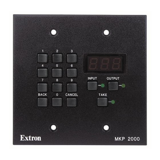
3 3 4 4 Figure 17. MKP 2000 Controls and Indicators 0, 1 through 9 buttons — Allow you to enter an input or output when you create a tie. Back button — Deletes the least-significant digit (first digit on the right) of an entered input or output number. -
Page 25: Front Panel Operations
LED display shows n-a (not available). Deselecting a Tie To deselect (break) a tie: Press Input On the keypad, press for the input. Press Output On the keypad, press the number of the output that you want to untie. Press Take MKP 2000 • Operation... -
Page 26: Viewing The Last Input Or Output Tied From The Mkp
Edit these addresses and set the host control as follows: Simultaneously press and hold the , and buttons until the LED Input Output Take display changes (approximately 2 seconds), then release the buttons (see figure 18 the next page). MKP 2000 • Operation... - Page 27 Release 1 9 2 the buttons. TAKE The LED display shows the most-significant octet of the MKP 2000 IP address. Figure 18. Selecting Setup Mode Press the button to change the value shown in the LED display, cycling • Input through the various IP addresses and the host control settings (see figure 19).
-
Page 28: Host Control Port Setting And Pass-Through Communications
When the MKP is selected as primary, the MKP directly controls the matrix switcher • via its Switch RS-232 port or LAN port. Selected as secondary, the MKP controls the matrix switcher through connection to the primary MKP IP address. MKP 2000 • Operation... -
Page 29: Control Panel Security Lockout (Executive Mode)
Control Panel Security Lockout (Executive Mode) The MKP 2000 provides the following three levels of front panel security lockout (executive modes): • Panel Locked mode — All front panel controls are locked. Selections and setup cannot be performed from the front panel. -
Page 30: Performing A Hard Reset
Hold Reset MKP (see figure 25). Press and hold the Reset button while you apply power to the MKP. Power The LED flashes on and off. Release the Reset button. Figure 25. Performing a Hard Reset MKP 2000 • Operation... -
Page 31: Remote Control
If the MKP receives a valid matrix switcher SIS command on its Host RS-232 port, it redirects the command to its Switch RS-232 port only if the MKP is set to pass-through mode (see Pass-through (RS-232 port redirect) on page 28 to set the pass-through mode). MKP 2000 • Remote Control... -
Page 32: Ethernet Link
When a local event such as a front panel operation occurs, the MKP responds by sending a message to the host. The MKP-initiated messages are listed below: (c) Copyright 2006, Extron Electronics, MKP 2000, Vx.xx, 60-682-00 (for RS-232 connection) c) Copyright 2006, Extron Electronics, MKP 2000, Vx.xx, 60-682-00... -
Page 33: Error Messages
SIS commands. Refer to the applicable matrix switcher’s manual. Symbols are used throughout the tables to represent variables in the command/response fields. Command and response examples are shown throughout the MKP SIS commands table. MKP 2000 • Remote Control... -
Page 34: Symbol Definitions
1800 2400 3600 4800 9600 14400 19200 28800 , or 38400 57600 115200 = Parity (1st character only) = Odd, Even, None (default), Mark, Space = # of data bits = 7 or 8 (default) MKP 2000 • Remote Control... -
Page 35: Timeout
= Executive mode = Administrator mode (panel unlocked) = User mode = Panel locked Timeout Pauses of 10 seconds or longer between command ASCII characters result in a timeout. The command operation is aborted with no other indication. MKP 2000 • Remote Control... -
Page 36: Command And Response Table For Sis Commands
Bootstrap version (x.xx) X& = Verbose firmware version-description-upload date/time. Reset Names reset Erase all presets, preset names, ZXXX input names, and output names. Absolute reset Perform a Names reset plus ZQQQ restoring all IP settings. MKP 2000 • Remote Control... - Page 37 (with the exception of output 0, which cannot be enabled. See the Data description, on the next page, for a detailed explanation. Outputs 33 through 999 are invalid selections for a 32-output matrix switcher. NOTE: MKP 2000 • Remote Control...
- Page 38 Each byte is returned most-significant bit first (such as input 7 in byte 0), least-significant bit last (such as input 0 in NOTE: byte 0). Bytes are returned in sequential order (byte 0, byte 1, byte 2,...byte 124). MKP 2000 • Remote Control...
- Page 39 2 = Daylight Savings Time on (Europe), 3 = Daylight Savings Time on (Brazil) = IP Address (xxx.xxx.xxx.xxx) = Hardware ( MAC) address (Example: 00-05-A6-##-##-##) = Connection priority 0 = Primary, 1 = Secondary = Password 12 digits, alphanumeric MKP 2000 • Remote Control...
- Page 40 2 = Daylight Savings Time on (Europe), 3 = Daylight Savings Time on (Brazil) = IP Address (xxx.xxx.xxx.xxx) = Password 12 digits, alphanumeric = Web page priority 0 = Internal (default on power up), 1 = User MKP 2000 • Remote Control...
-
Page 41: Html Operation
, is the correct value for this field. 192.168.254.253 If you want the browser to display a page other than the default MKP 2000 web page (such as a custom page that you have created and uploaded), enter a slash (/) after the address, and the name of the web page file you want to display. -
Page 42: Viewing System Status
29), which is the factory-installed default startup page with the file name nortxe_index.html You can now select the tabs at the top of the screen to display additional pages that enable you to configure and control the MKP 2000. Viewing System Status page on the... -
Page 43: Using The Configuration Pages
To access the page from other MKP HTML web pages, click the System Status Status tab. This page shows only the current status of the MKP 2000. To change any of this information, select the tab to display the page. Configuration... -
Page 44: Ip Settings Section
IP Settings Section In this section, you enter all IP-related information for your MKP 2000. After making all desired changes to the fields in this section, click the button at the bottom of the Submit section to implement your changes. Click... -
Page 45: Switcher Control Settings Section
If Primary – RS-232 has been selected in the MKP Connection Priority section, select one of the following radio buttons to specify how the Host RS-232 port will function: MKP 2000 — Commands received on the Host RS-232 port are executed by the MKP. •... -
Page 46: Date/Time Settings Fields
, and . A drop-down scroll box appears. (time) zone Click and drag the slider, or click the scroll up or scroll down button, until the desired variable is visible. Click on the desired variable. MKP 2000 • HTML Operation... -
Page 47: Port (Rs-232) Settings Page
• Baud rate: 9600 • Data bits: 8 • Parity: None Stop bits: • • Flow control: None Click to confirm your settings. To reject the changes and restore the previous Submit settings, click Cancel MKP 2000 • HTML Operation... -
Page 48: Passwords Page
To remove an assigned password, follow these steps: In the field, clear any text, then enter a Administrator Password User Password single space. Repeat step 1 in the or the field. Re-enter Admin Password Re-enter User Password Click the button. Submit MKP 2000 • HTML Operation... -
Page 49: Firmware Upgrade Page
Select the latest firmware file for the MKP and download it. Note the folder to which you save the firmware file. NOTE: The firmware file name may read, in part, MKP 2000 or MKP 3000. This is normal. The firmware is the same for both products. - Page 50 NOTE: You can obtain the latest version of firmware only by downloading it from the Extron website. If the computer connected to your MKP has no network access, you must download the firmware to a computer with network access, then copy it to your computer hard disk. MKP 2000 • HTML Operation...
-
Page 51: Using The File Management Page
NOTE: If you want a page you created and uploaded to be the default startup page, name that file "index.html". Figure 36. File Management Page NOTE: The files listed in figure 36 are shown as examples only and may not be present on your MKP 2000. MKP 2000 • HTML Operation... -
Page 52: Uploading Files
Uploading Files Files to be uploaded to the MKP 2000 must contain only valid alphanumeric characters and underscores. No spaces or special characters (symbols) are allowed. NOTE: The following characters are invalid: {space} - ‘ [ ] { } , ; | and \ . -
Page 53: Reference Information
MKP 2000 on a flat surface. This type of installation can include a desk or podium, or a control panel or dashboard, where the back is protected and does not require an electrical box. - Page 54 Full Size 3.38” 2.63” VOLUME Circuit Board Box (behind front panel) Cut-out area should be slightly larger. MKP 2000 Figure 37. Panel Mount Cutout Template MKP 2000 • Reference Information...
- Page 55 Extron Electronics makes no further warranties either expressed or implied with respect to the product and its quality, performance, merchantability, or fitness for any particular use. In no event will Extron Electronics be liable for direct, indirect, or consequential damages resulting from any defect in this product even if Extron Electronics has been advised of such damage.
Need help?
Do you have a question about the MKP 2000 and is the answer not in the manual?
Questions and answers