Extron electronics MKP 2000 User Manual
Hide thumbs
Also See for MKP 2000:
- Specifications (2 pages) ,
- User manual (35 pages) ,
- User manual (56 pages)
Table of Contents
Advertisement
Quick Links
Download this manual
See also:
User Manual
Extron Electronics, USA
Extron Electronics, Europe
1230 South Lewis Street
Beeldschermweg 6C
Anaheim, CA 92805
3821 AH Amersfoort, The Netherlands
800.633.9876 714.491.1500
+800.3987.6673 +31.33.453.4040
FAX 714.491.1517
FAX +31.33.453.4050
www.extron.com
© 2007 Extron Electronics. All rights reserved.
Extron Electronics, Asia
Extron Electronics, Japan
135 Joo Seng Rd. #04-01
Kyodo Building, 16 Ichibancho
PM Industrial Bldg., Singapore 368363
Chiyoda-ku, Tokyo 102-0082
+800.7339.8766 +65.6383.4400
Japan
FAX +65.6383.4664
+81.3.3511.7655 FAX +81.3.3511.7656
User's Manual
MKP 2000
Remote Control Panel
68-971-01 Rev. C
01 07
Advertisement
Table of Contents

Related Manuals for Extron electronics MKP 2000


Summary of Contents for Extron electronics MKP 2000
- Page 1 3821 AH Amersfoort, The Netherlands PM Industrial Bldg., Singapore 368363 Chiyoda-ku, Tokyo 102-0082 68-971-01 Rev. C 800.633.9876 714.491.1500 +800.3987.6673 +31.33.453.4040 +800.7339.8766 +65.6383.4400 Japan 01 07 FAX 714.491.1517 FAX +31.33.453.4050 FAX +65.6383.4664 +81.3.3511.7655 FAX +81.3.3511.7656 www.extron.com © 2007 Extron Electronics. All rights reserved.
- Page 2 Sie verbrauchte Batterien bitte gemäß den Herstelleranweisungen. Keine Zusatzgeräte • Verwenden Sie keine Werkzeuge oder Zusatzgeräte, particular use. In no event will Extron Electronics be liable for direct, indirect, or die nicht ausdrücklich vom Hersteller empfohlen wurden, da diese eine Gefahrenquelle darstellen können.
- Page 4 Precautions, cont’d Quick Start Guide — MKP 2000 Install and set up the MKP 2000 as follows: Step 1 Turn all of the equipment off, or disconnect it from its power source. Step 2 Install the cables to and from the control panel in a wall, podium, or desk.
-
Page 5: Table Of Contents
........... 4-1 RS-232 Links ................4-2 Routing matrix switcher commands ........4-2 Ethernet Link ................4-3 Default IP address ..............4-3 MKP 2000 Remote Control Panel • Quick Start Guide QS-2 MKP 2000 Remote Control Panel • Table of Contents... - Page 6 Updating the firmware using a direct computer-to- MKP connection ............. 5-14 All trademarks mentioned in this manual are the properties of their respective owners. 68-971-01 C 01 07 MKP 2000 Remote Control Panel • Table of Contents MKP 2000 Remote Control Panel • Table of Contents...
-
Page 7: Chapter 1 • Introduction
Table of Contents, cont’d MKP 2000 Remote Control Panel Chapter One Introduction About the MKP 2000 Remote Control Panel MKP 2000 Remote Control Panel • Table of Contents... -
Page 8: About The Mkp 2000 Remote Control Panel
Web pages. Input The MKP 2000 panel is mounted in a two-gang wall plate that can be installed in a wall, conference table, podium, or other INPUT OUTPUT convenient location. -
Page 9: Chapter 2 • Installation
CANCEL TAKE MKP 2000 MKP 2000 Control System Chapter Two Figure 1-2 — MKP 2000 application diagram Installation MKP Installation Overview UL Requirements for Wall Box Installation Installation Procedures Rear Panel and Side Panel Connections MKP 2000 Remote Control Panel • Introduction... -
Page 10: Mkp Installation Overview
UL Listed electrical The following Underwriters Laboratories (UL) requirements boxes are recommended. See “UL Requirements for pertain to the installation of the MKP 2000 into a wall or Wall Box Installation” on the next page. furniture (figure 2-1). -
Page 11: Preparing The Site And Installing The Mounting Bracket (Mud Ring) Or Wall Box
To meet the UL listing requirements, the MKP device furniture. must be installed in a wall box. Cut out the wall or furniture material from the marked area. MKP 2000 Remote Control Panel • Installation MKP 2000 Remote Control Panel • Installation... -
Page 12: Mounting The Mkp To The Mounting Bracket (Mud Ring) Or Wall Box
Take care not to damage the cables, which fit behind the MKP, at the back of the wall box. Mount the MKP’s faceplate to the mud ring or wall box with machine screws (figure 2-5). MKP 2000 Remote Control Panel • Installation MKP 2000 Remote Control Panel • Installation... -
Page 13: Rear Panel And Side Panel Connections
2-14, to wire the connector. -2 3 HOST RS-232 IT C -2 3 SWITCH RS-232 12 VDC Figure 2-6 — MKP rear and side panels MKP 2000 Remote Control Panel • Installation MKP 2000 Remote Control Panel • Installation... -
Page 14: Control Connections
MKP 2000 Matrix Switcher MKP 2000 direct insertion connector, and tighten the captive screws. Figure 2-9 — Direct MKP connection via the LAN port 2-10 MKP 2000 Remote Control Panel • Installation MKP 2000 Remote Control Panel • Installation 2-11... -
Page 15: Tp Cable Termination
For pin assignments, see figure 2-11, at right. Switcher RS-232 MKP RS-232 – – – – – – – – – – – – Figure 2-12 — RS-232 cross-connection table 2-12 MKP 2000 Remote Control Panel • Installation MKP 2000 Remote Control Panel • Installation 2-13... -
Page 16: Power Supply Wiring
Alternatively, you can use the optional Extron P/S 123 Front Panel Operations Universal 12 VDC Power Supply, part #60-814-01, which can power up to ten Extron 12 VDC devices using only one AC Rear Panel Resets power connector. MKP 2000 Remote Control Panel • Installation 2-14... -
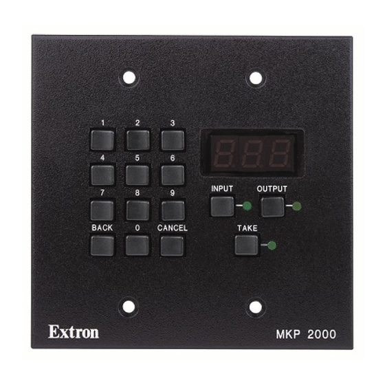
Page 17: Front Panel Controls And Indications
[see steps 3 and 4]). Figure 3-1 — MKP 2000 controls and indicators Use the numeric keys to select the desired input. 0, 1 through 9 buttons — Allow you to enter an input or output •... -
Page 18: Deselecting A Tie
(default = no pass-through) • MKP’s connection setting Primary — Controls the switcher directly. Secondary — Controls the switcher through another MKP and its Switch RS-232 port. MKP 2000 Remote Control Panel • Local Operation MKP 2000 Remote Control Panel • Local Operation... - Page 19 Connected to Control Though Switcher Primary (RS-232) INPUT OUTPUT OUTPUT OUTPUT Figure 3-4 — Selecting octet fields Figure 3-6 — Selecting the connection priority setting MKP 2000 Remote Control Panel • Local Operation MKP 2000 Remote Control Panel • Local Operation...
-
Page 20: Host Control Port Setting And Pass-Through Communications
MKP settings to their defaults. Control panel security lockout (executive mode) • Events (mode 3) reset — Restarts the communications The MKP 2000 provides the following three levels of front panel and control events. security lockout (executive modes): •... -
Page 21: Performing A Hard Reset
Local Operation, cont’d To perform a soft reset of the MKP 2000, Turn off power to the switcher. Press and hold the Reset (R) button until the Reset LED Press and hold the Reset button on the rear panel while blinks off once (for events reset), twice (for IP system you apply AC power to the MKP (figure 3-9). -
Page 22: Chapter 4 • Sis™ Operation
Local Operation, cont’d MKP 2000 Remote Control Panel Chapter Four ™ Operation RS-232 Links Ethernet Link Host-to-MKP Instructions MKP-Initiated (Unsolicited) Messages MKP Error Responses Using the Command/Response Table 3-12 MKP 2000 Remote Control Panel • Local Operation... -
Page 23: Rs-232 Links
MKP is set to pass-through mode. See the pass- initiated messages are listed below (underlined). through port redirect command set on page 4-9 to set the pass- (c) Copyright 2006, Extron Electronics, MKP 2000, Vx.xx, through mode. 60-682-00 (for RS-232 connection) (c) Copyright 2006, Extron Electronics, MKP 2000, Vx.xx,... -
Page 24: Mkp Error Responses
E14 — Illegal command for this configuration E24 — Privilege violation (Ethernet, Extron software only) E99 — Invalid or no response from target switcher ™ ™ MKP 2000 Remote Control Panel • SIS Operation MKP 2000 Remote Control Panel • SIS Operation... -
Page 25: Symbol Definitions
{space} + ~ @ = ‘ ’ [ ] { } < > “ ” ; : | \ and ?. Space ™ ™ MKP 2000 Remote Control Panel • SIS Operation MKP 2000 Remote Control Panel • SIS Operation... - Page 26 0 = Internal (default on power up) 1 = User = Executive mode 0 = Administrator mode (panel unlocked) 1 = User mode 2 = Panel locked ™ ™ MKP 2000 Remote Control Panel • SIS Operation MKP 2000 Remote Control Panel • SIS Operation...
- Page 27 ™ Operation, cont’d ™ ™ 4-10 MKP 2000 Remote Control Panel • SIS Operation MKP 2000 Remote Control Panel • SIS Operation 4-11...
- Page 28 ™ Operation, cont’d ™ ™ 4-12 MKP 2000 Remote Control Panel • SIS Operation MKP 2000 Remote Control Panel • SIS Operation 4-13...
- Page 29 ™ Operation, cont’d ™ ™ 4-14 MKP 2000 Remote Control Panel • SIS Operation MKP 2000 Remote Control Panel • SIS Operation 4-15...
-
Page 30: Chapter 5 • Html Operation
™ Operation, cont’d MKP 2000 Remote Control Panel Chapter Five HTML Operation Downloading the Startup Page Viewing System Status Using the Configuration Pages Using the File Management Page Special Characters ™ 4-16 MKP 2000 Remote Control Panel • SIS Operation... -
Page 31: Downloading The Startup Page
“index.html,” the MKP downloads “index.html” as If you want the browser to display a page other than the the default startup page. default MKP 2000 Web page (such as a custom page that • If neither file is found, the MKP downloads the... -
Page 32: Viewing System Status
To access the System Status page from other MKP HTML web pages, click the Status tab. This page shows only the current status of the MKP 2000. To change any of this information, select the Configuration tab to display the System Settings page. -
Page 33: Ip Settings Section
In this section, you enter all IP-related information for your A subnet is a subset of a network — a set of IP devices that have MKP 2000. After making all desired changes to the fields in this portions of their IP addresses in common. The Subnet Mask... -
Page 34: Host Control Port Settings
Host RS-232 port will function: controllable from the MKP. • MKP 2000 — Commands received on the Host RS-232 When you have set the size of the connected switcher’s port are executed by the MKP. input/output matrix, the LED display shows... -
Page 35: Port (Rs-232) Settings Page
The Passwords page (figure 5-5) lets you assign passwords to Daylight Savings Time, on the dates that the time control access to the MKP 2000 Web pages. change occurs in the United States of America and parts Passwords are case sensitive and are limited to 12 uppercase of Europe and Brazil. -
Page 36: Clearing A Password
• Download tab > Firmware (from the sidebar menu) > Password field. MKP 2000 Click the Submit button to set the password(s). • MKP 2000 product page > Downloads > MKP 2000 (in FIRMWARE section) Clearing a password To remove an assigned password, follow these steps: Select the latest firmware file for the MKP and download it. -
Page 37: Updating The Firmware Using A Direct Computer-To-Mkp Connection
Click OK, and close the remaining windows. Open Internet Explorer, and enter the IP address of your MKP in the Address field. 5-14 MKP 2000 Remote Control Panel • HTML Operation MKP 2000 Remote Control Panel • HTML Operation 5-15... -
Page 38: Using The File Management Page
Selecting a file — From the Select menu, select a file name, or select All to select all uploaded files. Files to be uploaded to the MKP 2000 must contain only valid alphanumeric characters and underscores. No spaces or special characters (symbols) are allowed. -
Page 39: Special Characters
Cannot start with a number or a dash • Cannot end with a dash These guidelines do not apply to input, output, and preset names. A ppendix A Reference Information Specifications Part Numbers Mounting and Cabling Specifications 5-18 MKP 2000 Remote Control Panel • HTML Operation... -
Page 40: Specifications
™ Included parts ® Microsoft Internet Explorer, Telnet These items are included in each order for an MKP 2000: General Included parts Part number External power supply ....100 VAC to 240 VAC, 50/60 Hz, external, autoswitchable; to 12 VDC, 1 A, regulated... -
Page 41: Cables
Full Size MKP 2000 on a flat surface. This type of installation can include a desk or podium, or a control panel or dashboard, where the Figure A-1 — Panel mount cutout template back is protected and does not require an electrical box. -
Page 42: Extron Comm-Link Cable
Two 22 AWG Jacket (White and Violet or Blue) One 24 AWG Tinned Copper Drain Wire (foil-shielded group) Figure A-2 — Extron Comm-Link cable MKP 2000 Remote Control Panel • Reference Information MKP 2000 Remote Control Panel • Reference Information... - Page 43 Reference Information, cont’d MKP 2000 Remote Control Panel • Reference Information...
Need help?
Do you have a question about the MKP 2000 and is the answer not in the manual?
Questions and answers