Table of Contents
Advertisement
Quick Links
Extron Electronics, USA
Extron Electronics, Europe
1230 South Lewis Street
Beeldschermweg 6C
Anaheim, CA 92805
3821 AH Amersfoort, The Netherlands
800.633.9876 714.491.1500
+800.3987.6673 +31.33.453.4040
FAX 714.491.1517
FAX +31.33.453.4050
www.extron.com
© 2007 Extron Electronics. All rights reserved.
Extron Electronics, Asia
Extron Electronics, Japan
135 Joo Seng Rd. #04-01
Kyodo Building, 16 Ichibancho
PM Industrial Bldg., Singapore 368363
Chiyoda-ku, Tokyo 102-0082
+800.7339.8766 +65.6383.4400
Japan
FAX +65.6383.4664
+81.3.3511.7655 FAX +81.3.3511.7656
User's Manual
MCP 1000
Remote Control Panel
68-456-01 Rev. C
01 07
Advertisement
Table of Contents

Related Manuals for Extron electronics MCP 1000


Summary of Contents for Extron electronics MCP 1000
- Page 1 User’s Manual MCP 1000 Extron Electronics, USA Extron Electronics, Europe Extron Electronics, Asia Extron Electronics, Japan Remote Control Panel 1230 South Lewis Street Beeldschermweg 6C 135 Joo Seng Rd. #04-01 Kyodo Building, 16 Ichibancho Anaheim, CA 92805 3821 AH Amersfoort, The Netherlands PM Industrial Bldg., Singapore 368363...
- Page 2 Precautions Safety Instructions • English FCC Class A Notice Warning Power sources • This equipment should be operated only from the power source This symbol is intended to alert the user of important indicated on the product. This equipment is intended to be used with a main power operating and maintenance (servicing) instructions in Note: This equipment has been tested and found to comply with the limits for a system with a grounded (neutral) conductor.
-
Page 4: Table Of Contents
..................1-3 Button functions ..............1-3 Simple Instruction Set (SIS) ........... 1-3 Mounting options ..............1-3 MCP 1000 as part of a Matrix 3200/6400 system ....1-4 Comm-link requirements ............1-4 Chapter Two • Installation ............. 2-1 Mounting the MCP 1000 ............ - Page 5 ................A-2 Included Parts Chapter One ................A-3 Cables ....................A-3 Introduction About this Manual About the MCP 1000 Features All trademarks mentioned in this manual are the properties of their respective owners. 68-456-01 C 01 07 MCP 1000 • Table of Contents...
-
Page 6: About This Manual
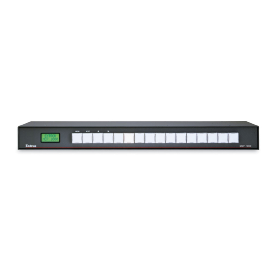
MCP 1000S — and provides information on how to operate Features and confi gure them. In this manual, "MCP 1000" is used to refer to either unit. The • Front panel includes 16 large, illuminated push buttons. terms "master," "slave," "MCP 1000M," and "MCP 1000S" are •... -
Page 7: Mcp 1000 As Part Of A Matrix 3200/6400 System
Matrix 3200/6400 switcher, and they can be mixed with MKP 1000 keypads. For additional information, see the MKP 1000 User’s Manual. As with the MKP 1000, the status of MCP 1000 units can be displayed on the front panel (FPC 1000) of the Matrix 3200/6400. Demo... -
Page 8: Mounting The Mcp 1000
MBD 149 rack mounting kit (part #70-077-03). UL requirements The following Underwriters Laboratories (UL) requirements pertain to the installation of the MCP 1000 into or onto a rack. Elevated operating ambient — If the equipment is installed in a closed or multi-unit rack assembly, the... -
Page 9: Rs-232 Connectors (Master)
Switcher to be controlled AUD.VID. SWITCHER Switcher — Use this 9-pin connector for communication MCP 1000 (master) between the MCP 1000 and a comm port on the switcher that MENU NEXT will be controlled by the MCP 1000. AUD.VID. 1 2 3 4 5 6 7 8 9 10... -
Page 10: Extron's Plenum Comm-Link Cable
Extron’s Plenum Comm-Link cable Extron’s Plenum Comm-Link cable was designed for use with the MCP 1000 and MKP 1000. If another cable will be used, it must meet the following specifi cations: Trimming the cable jacket A (red) —... -
Page 11: Changing The Front Panel Button Labels
Installation, cont’d Changing the Front Panel Button Labels The 16 buttons on the MCP 1000 are not marked for operation. You can remove the button caps to reveal a label plate (see the fi gure below). Remove each cap and insert a label (icon or text) for each button to identify its assignment. -
Page 12: Chapter Three • Operation
Installation, cont’d MCP 1000 Remote Control Panel Chapter Three Operation Front Panel Features Application Examples Setting Up the Operation Mode 2-10 MCP 1000 • Installation... -
Page 13: Front Panel Features
Front Panel Features This section shows some examples of how the MCP 1000 can The buttons on the MCP 1000 front panel enable you to set up be used to perform various functions with a variety of devices. and operate the MCP and to control a connected switcher. -
Page 14: Video Switcher - Sis Command: I
MCP 1000 acts like a switcher for a specifi c output number on chapter, for two examples of slave units used with a master unit. the matrix. For example, if the MCP 1000 is set up for output 5 A slave sends signals by comm-link to the MCP 1000M or BME. -
Page 15: Star Confi Guration
1000 feet (305 meters). See the fi gure on the next page. MCP 1000 • Operation MCP 1000 • Operation... -
Page 16: Lcd Display
Title screen examples operational, a title screen appears in the If ViewMode = <OFF> case, if the MCP 1000 is in preset mode and is set up to work display product name. LCD display. If view mode is off, the... -
Page 17: Room Mode
LCD display. Setup fl ow charts The MCP 1000 slave mode fl ow chart is on page 3-11, and the MCP 1000 master mode fl ow chart is on page 3-12. On the applicable fl... -
Page 18: Specifi Cations
Operation, cont’d MCP 1000 Remote Control Panel A ppendix A Specifi cations, Part Numbers, and Accessories Specifi cations Included Parts Cables MCP 1000 master mode fl ow chart 3-12 MCP 1000 • Operation... -
Page 19: Included Parts
Baud rate and protocol ....9600 baud, 8 data bits, 1 stop bit, no parity These items are included in each order for an MCP 1000: Serial control pin confi gurations . 2 = TX, 3 = RX, 5 = GND... - Page 20 Specifi cations, Part Numbers, Accessories, cont’d MCP 1000 • Specifi cations, Part Numbers, and Accessories MCP 1000 • Specifi cations, Part Numbers, and Accessories...
- Page 21 Specifi cations, Part Numbers, Accessories, cont’d MCP 1000 • Specifi cations, Part Numbers, and Accessories...
Need help?
Do you have a question about the MCP 1000 and is the answer not in the manual?
Questions and answers