Table of Contents
Advertisement
Quick Links
Download this manual
See also:
User Manual
Extron Electronics, USA
Extron Electronics, Europe
1230 South Lewis Street
Beeldschermweg 6C
Anaheim, CA 92805
3821 AH Amersfoort
USA
The Netherlands
714.491.1500
+31.33.453.4040
www.extron.com
Fax 714.491.1517
Fax +31.33.453.4050
© 2005 Extron Electronics. All rights reserved.
Extron Electronics, Asia
Extron Electronics, Japan
135 Joo Seng Road, #04-01
Kyodo Building
PM Industrial Building
16 Ichibancho
Singapore 368363
Chiyoda-ku, Tokyo 102-0082 Japan
+65.6383.4400
+81.3.3511.7655
Fax +65.6383.4664
Fax +81.3.3511.7656
User's Manual
RCP 2000
Remote Control Panel
68-792-01 Rev. C
03 05
Advertisement
Table of Contents

Subscribe to Our Youtube Channel
Related Manuals for Extron electronics RCP 2000


Summary of Contents for Extron electronics RCP 2000
- Page 1 3821 AH Amersfoort PM Industrial Building 16 Ichibancho 68-792-01 Rev. C The Netherlands Singapore 368363 Chiyoda-ku, Tokyo 102-0082 Japan 714.491.1500 +31.33.453.4040 +65.6383.4400 +81.3.3511.7655 03 05 www.extron.com Fax 714.491.1517 Fax +31.33.453.4050 Fax +65.6383.4664 Fax +81.3.3511.7656 © 2005 Extron Electronics. All rights reserved.
- Page 2 In no event will Extron Electronics be liable for direct, indirect, representar riesgo de electrocución.
- Page 3 Attach one of the RS-232 cables provided with the RCP 2000 between the RS-232 port on the rear panel of the ISS and the To Switcher port on the rear panel of the RCP 2000; or attach a network cable between the ISS and RCP 2000 rear panel Ethernet ports.
-
Page 4: Table Of Contents
Chapter 1 • Introduction Six sizes of male-to-male RS-232 cables are provided with the ............1-1 RCP 2000, any of which can be used to connect the SGA or Features ..................1-2 ISS switcher’s RS-232 port to the RCP 2000’s To Switcher (RS-232) port. -
Page 5: Chapter 1 • Introduction
Appendix A • Specifications, Parts, and Accessories ..................A-1 Specifications ................. A-2 Part Numbers ................A-3 All trademarks mentioned in this manual are the properties of their respective owners. Chapter One 68-792-01 Rev. C 03 05 Introduction Features RCP 2000 • Table of Contents... -
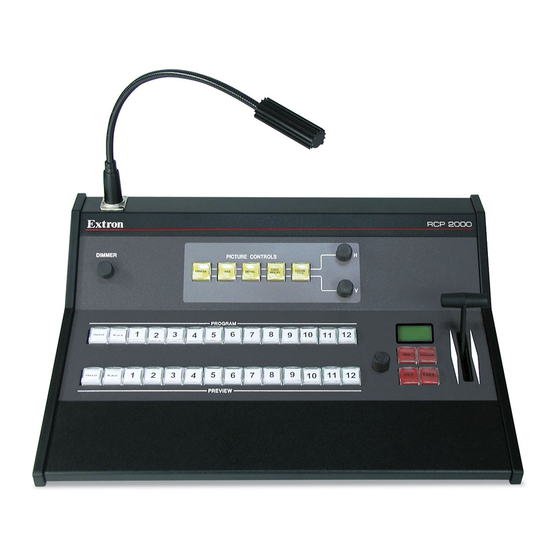
Page 6: Features
The RCP 2000 offers bi-directional Ethernet communication for the ISS 108/408, and RS-232 communication for both the ISS and the SGS 408. The RCP 2000 allows a switch to occur from either the RCP or the seamless switcher while the other device is being updated. -
Page 7: Rear Panel Connectors
Select a different input to check for an image. Reset button — Use an Extron Tweeker or a small screwdriver to press this recessed button to reset the RCP 2000 unit. See Resetting the Unit in chapter 3 for additional information. -
Page 8: Application Example
RCP 2000 to ISS 108/408, SGS 408 RS-232 link Both ends of the RS-232 cable must be terminated with a 9-pin The following diagram is an example of the RCP 2000 connected male D connector. See figure 2-3 for RS-232 pin assignments. -
Page 9: Chapter 3 • Operation
Installation, cont’d • When connecting the RCP 2000 directly (no intermediate RCP 2000 Remote Control Panel device present, such as a network hub) to the ISS 108/408, you must use a crossover cable. See the table on the next page for RJ-45 crossover cable connections. -
Page 10: Top Panel Controls
Transmit and Receive LEDs — These LEDs flicker whenever to be connected for low intensity illumination of the control Ethernet data is being transmitted or received by the RCP 2000. panel. The data traffic is between the RCP and the SGS 408 or the Lamp dimmer control —... -
Page 11: Using The Picture Controls
To adjust the vertical centering, rotate the V adjustment press the desired picture control button and rotate this knob to knob. make the adjustment. To adjust the horizontal centering, rotate the H adjustment knob. RCP 2000 • Operation RCP 2000 • Operation... -
Page 12: Detail Adjustments
For a description of each effect, and the technique to implement it, see the instructions for the effect in The different types of wipes available on the RCP 2000 are this section. Unless otherwise indicated, the effects are available described in this section. -
Page 13: Curtain Wipe
LCD screen, showing the currently selected wipe. Rotate the Adjust knob next to the buttons and select a wipe from the 21 choices presented in sequence (see figure 3-8 on the next page). RCP 2000 • Operation RCP 2000 • Operation... -
Page 14: Implementing An Effect
Implementing an effect The LCD screen displays “Unit reset” when the Mode 1 To implement an effect after it has been set up on the RCP 2000, reset is complete. follow these steps. (For a title effect, see Implementing a title, on Nothing happens if the second, momentary press does the next page.) -
Page 15: Chapter 4 • Remote Control
Operation, cont’d Mode 3 — Pressing and holding the Reset button until the front R E S E T RCP 2000 Remote Control Panel M O D E 3 panel LCD display shows “Reset Mode 3” (10 seconds), then immediately pressing the button momentarily (for less than one second) causes an absolute system reset to factory defaults. -
Page 16: Manual Ip Setup
Press the Size button and use the H adjust knob to change the third block of the address. The RCP 2000 unit ships with default server (ISS) and client • Press the Center button and use the H adjust knob to (RCP) IP addresses, as well as Subnet Mask and Gateway change the fourth block of the address. -
Page 17: Network Ip Setup And Control
Once the IP addresses have been changed, if required, you can of the RCP unit and to access the Web pages for the controlled contact and control the RCP 2000 by using Web pages that are switcher. The System Settings screen can be accessed from the resident, in firmware, on the RCP unit. -
Page 18: Firmware Upgrade
CAUTION cause your RCP unit to stop functioning. The original factory-installed firmware is permanently available on the RCP 2000. If the attempted upload of new firmware fails for any reason, the RCP 2000 reverts to the factory-installed firmware. RCP 2000 • Remote Control... -
Page 19: File Management
To delete a file from the RCP unit, find the file on the file list and select the Delete check box. When you are ready to delete the selected file(s), click the Delete Files button. RCP 2000 • Remote Control RCP 2000 • Remote Control... -
Page 20: Using Network Switcher Control
Remote Control, cont’d RCP 2000 Remote Control Panel Figure 4-7— ISS Control screen Appendix Using network switcher control To use network switcher control, follow these steps: Set the level of control desired: video/audio, video only, or audio only. Select the Program (output) that you want to switch. - Page 21 Compliances ......... CE, FCC Class A, VCCI, AS/NZS, ICES MTBF ..........30,000 hours Warranty ........3 years parts and labor Specifications are subject to change without notice. RCP 2000 • Specifications, Parts, and Accessories RCP 2000 • Specifications, Parts, and Accessories...
- Page 22 Specifications, Parts, and Accessories, cont’d RCP 2000 • Specifications, Parts, and Accessories RCP 2000 • Specifications, Parts, and Accessories...
- Page 23 Specifications, Parts, and Accessories, cont’d RCP 2000 • Specifications, Parts, and Accessories...
Need help?
Do you have a question about the RCP 2000 and is the answer not in the manual?
Questions and answers