
Related Manuals for Mitsubishi Electric QJ71MT91


Summary of Contents for Mitsubishi Electric QJ71MT91
- Page 1 MODBUS/TCP Interface Module User's Manual -QJ71MT91 -GX Configurator-MB (SW1D5C-QMBU-E)
-
Page 3: Safety Precautions
SAFETY PRECAUTIONS (Always read these instructions before using this equipment.) Before using this product, please read this manual and the relevant manuals introduced in this manual carefully and pay full attention to safety to handle the product correctly. The instructions given in this manual are concerned with this product. - Page 4 CAUTION Do not bundle the control wires and the communication cables with the main circuit and the power wires, and do not install them close to each other. They should be installed at least 100 mm (3.94 in.) away from each other. Failure to do so may generate noise that may cause malfunctions.
- Page 5 CAUTION Connectors for external connection must be crimped or pressed with the tool specified by the manufacturer, or must be correctly soldered. Incomplete connections could result in short circuit, fire, or malfunction. Securely connect the connector to the module. Failure to do so may cause malfunction. ...
- Page 6 CAUTION Before performing online operations (especially, program modification, forced output or operating status change) by connecting a peripheral device to a running CPU, read the manual carefully and ensure the safety. Incorrect operation will cause mechanical damage or accidents. ...
-
Page 7: Conditions Of Use For The Product
CONDITIONS OF USE FOR THE PRODUCT A - 5 A - 5... -
Page 8: Revisions
REVISIONS The manual number is given on the bottom left of the back cover. Print Date Manual Number Revision Jan., 2004 SH (NA) -080446ENG-A First Edition Mar., 2004 SH (NA) -080446ENG-B Modifications Section 7.2.2, 8.3.2, 8.4, 8.6, 8.7, 9.2.2, 11.1, 11.4, 11.5 Nov., 2005 SH (NA) -080446ENG-C Modifications Section 4.3.10, 5.2.1, 6.1, 6.2, 6.6, 7.1, 7.3.1, 7.4.1 to 7.4.5, 8.2.2, 8.3.1, 8.3.3, 8.7.2, 9.1, 10.2, 10.3, 11.1, 11.2, 11.3.2, 11.3.3, 11.4... - Page 9 This manual confers no industrial property rights or any rights of any other kind, nor does it confer any patent licenses. Mitsubishi Electric Corporation cannot be held responsible for any problems involving industrial property rights which may occur as a result of using the contents noted in this manual.
-
Page 10: Table Of Contents
INTRODUCTION Thank you for purchasing the Mitsubishi Electric MELSEC-Q series programmable controller. Before using the equipment, please read this manual carefully to develop full familiarity with the functions and performance of the Q series programmable controller you have purchased, so as to ensure correct use. - Page 11 7.4.1 MODBUS device sizes ........................7-25 7.4.2 MODBUS device assignment parameters details ................7-26 7.4.3 Default assignment parameters ......................7-29 7.4.4 MODBUS extended file register assignment ................... 7-31 7.4.5 QJ71MT91 buffer memory assignment .................... 7-32 A - 9 A - 9...
- Page 12 10.1 Dedicated Instruction List and Available Devices ................10- 1 10.2 Z(P).MBRW ............................10- 2 10.3 Z(P).MBREQ ............................10-11 11 TROUBLESHOOTING 11- 1 to 11-51 11.1 Troubleshooting ............................ 11- 1 11.2 Confirming QJ71MT91 Status ......................11-12 A - 10 A - 10...
- Page 13 APPX- 1 to APPX- 8 Appendix 1 External Dimensions ......................APPX - 1 Appendix 2 Function Upgrade of the QJ71MT91 ................. APPX - 2 Appendix 3 Processing Time ......................... APPX - 2 Appendix 4 GX Developer Connection Setup Example ............... APPX - 6...
-
Page 14: Compliance With The Emc And Low Voltage Directives
(a) Section 2.1 describes the applicable programmable controller CPUs and compatible software packages. (b) Section 2.2 describes the devices necessary to configure a network. (c) Section 2.3 describes the system configurations that use the QJ71MT91 and the accessible range. (3) Performance and specifications (Chapter 3) (a) Section 3.1 provides the performance specifications of the QJ71MT91. - Page 15 (5) Usable functions (Chapter 5) Chapter 5 describes the functions of the QJ71MT91. (6) Settings and procedures necessary to operate the system (Chapter Chapter 6 describes the pre-operation settings and procedures. (7) Parameter setting of the QJ71MT91 (Chapter 7) Chapter 7 describes the parameter setting procedures and parameter details.
-
Page 16: About The Generic Terms And Abbreviations
A machine-specific address that is also referred to as the MAC (Media Access Control) address. This is used to identify the addresses of external devices over a network. Ethernet Address The Ethernet address of the QJ71MT91 can be verified on the MAC ADD column of the rating plate. MELSECNET/H... -
Page 17: Meanings And Definitions Of Terms
Memory provided for the programmable controller CPU to record the data handled in Device memory sequence program operation PRODUCT CONFIGURATION The following indicates the product configuration of the QJ71MT91 MODBUS/TCP interface module. Item name Model Quantity... -
Page 18: Overview
This manual explains the specifications, functions, programming, troubleshooting, and others of the MELSEC-Q series QJ71MT91 MODBUS/TCP interface module (hereafter abbreviated to the QJ71MT91). The QJ71MT91 is used to connect the MELSEC-Q series programmable controller to a MODBUS/TCP network. 1.1 Features... - Page 19 (b) Communication using dedicated instruction Dedicated instructions can be used to make communication from a sequence program at any timing. The QJ71MT91 supports the following two dedicated instructions. 1) MBRW instruction Reads/writes MODBUS device data from/to a slave. This enables slave data to be read out to the programmable controller CPU device memory or programmable controller CPU data to be written to the slave.
- Page 20 The slave function supports the following two functions. (a) Automatic response function The QJ71MT91 can automatically respond to a request message received from the master. A sequence program for the slave function is not needed. (b) MODBUS device assignment function Using MODBUS device assignment parameters, the MODBUS devices are correlated with the programmable controller CPU device memory.
- Page 21 Slave Master Slave Ethernet 1) In response to a request message from the master, the QJ71MT91 operates as a slave and returns a response message. 2) The QJ71MT91 operates as a master, and issues a request message to the slave.
- Page 22 ( 1) 1: It is recommended to use the utility package with the QJ71MT91. By making various parameter settings with the utility package, communication can be made without sequence programs.
-
Page 23: System Configuration
QJ71MT91, refer to the Q Corresponding MELSECNET/H Network System Reference Manual (Remote I/O network). (2) Support of the multiple CPU system When using the QJ71MT91 in a multiple CPU system, refer to the QCPU User's Manual (Multiple CPU System) first. 2 - 1... - Page 24 SYSTEM CONFIGURATION MELSEC-Q (3) Supported software packages Relation between the system containing the QJ71MT91 and software package is shown in the following table. GX Developer or GX Works2 is required to start up the system that uses the QJ71MT91. Software version...
-
Page 25: Devices Necessary For Network Configuration
Please note that the network must be installed by qualified networking specialists to take sufficient safety measures. The 10BASE-T or 100BASE-TX can be used to connect the QJ71MT91 to a network. The QJ71MT91 will distinguish between 10BASE-T and 100BASE-TX, and between the full duplex and half duplex communication mode according to the hub type. - Page 26 Take the following action on the QJ71MT91 side to prevent the influence of high frequency noise in the construction of a network system.
-
Page 27: System Configuration And Access Range
MELSEC-Q 2.3 System Configuration and Access Range This section provides the system configurations using the QJ71MT91. ( 1) The target devices available for communication with the QJ71MT91 are the following two kinds of devices. Master/slave device supporting the MODBUS/TCP protocol... - Page 28 (a) Accessible range of GX Developer Refer to Appendix 3 for the GX Developer connection setup examples. (b) Precautions for GX Developer connection When the QJ71MT91 and Ethernet module exist together on the same Ethernet, access cannot be made between the QJ71MT91 and Ethernet module.
-
Page 29: Precautions For System Configuration
SYSTEM CONFIGURATION MELSEC-Q 2.4 Precautions for System Configuration (1) For use in a redundant system When using the QJ71MT91 in a redundant system, refer to the QnPRHCPU User's Manual (Redundant System). 2 - 7 2 - 7... -
Page 30: Checking Function Version And Software Version
GX Configurator-MB. (1) Checking the function version of the QJ71MT91 The serial number and function version of the QJ71MT91 can be checked on the rating plate, front of the module, or system monitor window in GX Developer. - Page 31 To display the system monitor, select [Diagnostics] [System monitor] Product Inf. List button of GX Developer. 1) Production number display Since the QJ71MT91 does not support the production number display, “-” is displayed. POINT The serial number displayed on the Product Information List screen of GX Developer may differ from that on the rating plate or on the front of the module.
- Page 32 SYSTEM CONFIGURATION MELSEC-Q (2) Checking the software version of GX Configurator-MB The software version of GX Configurator-MB can be checked in GX Developer’s "Product information" screen. [Operating procedure] GX Developer [Help] [Product information] Software version 2 - 10 2 - 10...
-
Page 33: Specifications
SPECIFICATIONS MELSEC-Q 3 SPECIFICATIONS This chapter explains the QJ71MT91's performance specifications, I/O signals for programmable controller CPU, and buffer memory. For general specifications, refer to QCPU User's Manual (Hardware Design, Maintenance and Inspection). 3 - 1 3 - 1... -
Page 34: Performance Specifications
SPECIFICATIONS MELSEC-Q 3.1 Performance Specifications This section provides the performance specifications of the QJ71MT91. Specifications Reference Item Section 10BASE-T 100BASE-TX Data transmission rate 10Mbps 100Mbps Full-duplex: Not supported Back pressure congestion Flow control Half-duplex: control (half-duplex) Back pressure congestion control... -
Page 35: I/O Signals For Programmable Controller Cpu
Use prohibited ON : Error completed OFF: 1: Turns ON when the QJ71MT91 is ready after the programmable controller is turned ON from OFF or after the programmable controller CPU is reset. (Continued on next page) 3 - 3... - Page 36 SPECIFICATIONS MELSEC-Q Signal Direction QJ71MT91 → Programmable controller CPU Signal Direction Programmable controller CPU → QJ71MT91 Device Reference Device Reference Signal name Signal name section section MODBUS device assignment parameter setting existence Section ON : Parameters set 9.1.3 OFF: No parameters set...
-
Page 37: Applications And Assignment Of Buffer Memory
SPECIFICATIONS MELSEC-Q 3.3 Applications and Assignment of Buffer Memory 3.3.1 Buffer memory list A buffer memory list is given below. Read/ Initial Reference Write Setting Address Application Name Initial Value Section 0000 TCP ULP timer value (60) Set time = set value × 500ms 0001 TCP zero window timer value (20) - Page 38 SPECIFICATIONS MELSEC-Q Read Initial Reference /Write Setting Address Application Name Initial Value Section 0110 Local slave station port No. (272) Section 0111 Target slave port No. for automatic (273) communication function 0112 0113 System area (use prohibited) (274 to 275) 0114 CPU response monitoring timer value (10)
- Page 39 SPECIFICATIONS MELSEC-Q Read/ Initial Reference Address Application Name Initial Value Write Setting Section 0900 Device code (2304) 0901 Head device number Coil (2305) assignment 0902 Head coil number (2306) 0903 Assignment points (2307) 0904 Coil 093F assignment (Same as coil assignment 1) (2308 to 2367) 2 to 16 0940...
- Page 40 SPECIFICATIONS MELSEC-Q Read/ Initial Reference Address Application Name Initial Value Write Setting Section Section 0C05 Module LED ON LED ON status (3077) status status Section 11.2 0C06 0C0F System area (use prohibited) (3078 to 3087) 0C10 Basic parameter error code storage area (3088) 0C11 Automatic communication parameter error...
- Page 41 SPECIFICATIONS MELSEC-Q Read Initial Reference Address Application Name Initial Value /Write Setting Section 0E00 H / W Ethernet Ethernet 0E02 Local station Ethernet address information address address (3584 to 3586) 0E03 0E0F System area (use prohibited) (3587 to 3599) 0E10 0E11 IP packet reception count (3600 to 3601)
- Page 42 SPECIFICATIONS MELSEC-Q Read/ Initial Reference Address Application Name Initial Value Write Setting Section 0E70 0E71 UDP packet reception count (3696 to 3697) 0E72 Count of UDP packet reception Section 0E73 discarded due to sum check 11.3.1 (3698 to 3699) error 0E74 Total number of sent UDP 0E75...
-
Page 43: Modbus Standard Functions
1: The QJ71MT91 slave function does not support this function. However, it can be issued from the master (QJ71MT91) by use of the MBREQ instruction. 2: The function codes 07, 08, 11, 12 and 17 are the functions dedicated to the MODBUS serial protocol. - Page 44 MODBUS device and an access request is made from the master station. In this case, an error code will be stored into the error log of the QJ71MT91, and an exception code will be returned to the master.
-
Page 45: Frame Specifications
MODBUS STANDARD FUNCTIONS MELSEC-Q 4.2 Frame Specifications The frame specifications of MODBUS/TCP are indicated below. Area Name Area Size Description Used by the master for matching of the response Transaction ID 2 bytes message from the slave. Indicates the protocol of the PDU (protocol data Protocol ID 2 bytes unit). -
Page 46: Pdu Formats By Functions
MODBUS STANDARD FUNCTIONS MELSEC-Q 4.3 PDU Formats by Functions This section explains the PDU (protocol data unit) formats of the MODBUS standard functions. (1) Precautions for specifying device number in message When specifying a device number in a message, specify "(device number) - 1". However, it does not apply to the file number and device number specified for Read/Write file record. - Page 47 MELSEC-Q (3) Storage location of exception code and error code On error completion of processing in the slave (QJ71MT91), an exception code is sent to the master. (Refer to the "Response message format (when completed with an error)" given in Section 4.3.1 to 4.3.12.) The exception code is also stored into the QJ71MT91 buffer memory.
-
Page 48: Read Coils (Fc: 01)
MODBUS STANDARD FUNCTIONS MELSEC-Q 4.3.1 Read coils (FC: 01) Reads the statuses (ON/OFF) of one or more coils. Number of accessible devices with one message 1 to 2000 points (1) Request message format (Master → Slave) Function code Data Head coil number Read points Function code (0000... -
Page 49: Read Discrete Inputs (Fc: 02)
MODBUS STANDARD FUNCTIONS MELSEC-Q 4.3.2 Read discrete inputs (FC: 02) Reads the statuses (ON/OFF) of one or more inputs. Number of accessible devices with one message 1 to 2000 points (1) Request message format (Master → Slave) Function code Data Function code Head input number Read points... -
Page 50: Read Holding Registers (Fc: 03)
MODBUS STANDARD FUNCTIONS MELSEC-Q 4.3.3 Read holding registers (FC: 03) Reads the values of one or more holding registers. Number of accessible devices with one message 1 to 125 points (1) Request message format (Master → Slave) Function code Data Function code Head holding register number Read points... -
Page 51: Read Input Registers (Fc: 04)
MODBUS STANDARD FUNCTIONS MELSEC-Q 4.3.4 Read input registers (FC: 04) Reads the values of one or more input registers. Number of accessible devices with one message 1 to 125 points (1) Request message format (Master → Slave) Function code Data Function code Head input register number Read points... -
Page 52: Write Single Coil (Fc: 05)
MODBUS STANDARD FUNCTIONS MELSEC-Q 4.3.5 Write single coil (FC: 05) Writes a value (ON/OFF) to one coil. Number of accessible devices with one message 1 point (1) Request message format (Master → Slave) Function code Data Coil number ON/OFF specification Function code (0000 to FFFF... -
Page 53: Write Single Register (Fc: 06)
MODBUS STANDARD FUNCTIONS MELSEC-Q 4.3.6 Write single register (FC: 06) Writes a value to one holding register. Number of accessible devices with one message 1 point (1) Request message format (Master → Slave) Function code Data Holding register number Write data Function code (0000 to FFFF... -
Page 54: Write Multiple Coils (Fc: 15)
MODBUS STANDARD FUNCTIONS MELSEC-Q 4.3.7 Write multiple coils (FC: 15) Writes values (ON/OFF) to multiple coils. Number of accessible devices with one message 1 to 1968 points (1) Request message format (Master → Slave) : The number of points specified as the write points must be matched with the number of bits specified as the number of bytes. - Page 55 MODBUS STANDARD FUNCTIONS MELSEC-Q (When completed with an error) Function code Data Function code Exception code* : When completed with an error, the exception code and error code are stored into the buffer memory. Refer to Section 11.3 for the storage location, confirmation method and more details.
-
Page 56: Write Multiple Registers (Fc: 16)
MODBUS STANDARD FUNCTIONS MELSEC-Q 4.3.8 Write multiple registers (FC: 16) Writes values to multiple holding registers. Number of accessible devices with one message 1 to 123 points (1) Request message format (Master → Slave) 1: The number of points specified as the write points must be matched with the number of bytes. -
Page 57: Read File Record (Fc: 20) (Sc: 06)
(0001 to 007C (Number of bytes m 7) : The upper limit of the file number available for the QJ71MT91 slave function is equal to the file register size of the mounted programmable controller CPU. (Refer to Section 7.4.4.) (a) Specify the number of sub-requests "m" so that the PDU (protocol data unit) size in the request message does not exceed 253 bytes. - Page 58 MODBUS STANDARD FUNCTIONS MELSEC-Q (2) Response message format (Slave → Master) (When completed normally) Function code Data Sub-request 1 Reference Number of Number of Device data Device data Function code number response read bytes (n1 2+1) data bytes (m 2+N 2) (Number of read bytes n1 2 + 1) (Number of response data bytes m...
-
Page 59: Write File Record (Fc: 21) (Sc: 06)
1 to 122 points (1) Request message format (Master → Slave) 1: The upper limit of the file number available for the QJ71MT91 slave function is equal to the file register size of the mounted programmable controller CPU. (Refer to Section 7.4.4.) 2: N indicates the total number of write points (n1 + + nm). - Page 60 POINT Even if the slave (QJ71MT91) receives this function with the programmable controller CPU file register (ZR) set as read only (for example, the storage location of the file register [ZR] is a Flash card), the slave responds normally.
-
Page 61: Mask Write Register (Fc: 22)
MODBUS STANDARD FUNCTIONS MELSEC-Q 4.3.11 Mask write register (FC: 22) Masks the value stored in one holding register with AND or OR, and writes the masked value. Number of accessible devices with one message 1 point The masked value is written to the holding register as described below. (Target register’s current value AND mask value) (OR mask value AND mask value) -
Page 62: Read/Write Multiple Registers (Fc: 23)
MODBUS STANDARD FUNCTIONS MELSEC-Q 4.3.12 Read/Write multiple registers (FC: 23) Reads and writes data from and to multiple holding registers. Write is executed first and read is then executed. Number of accessible devices with one message Read: 1 to 125 points Write: 1 to 121 points (1) Request message format (Master →... -
Page 63: Functions
FUNCTIONS MELSEC-Q 5 FUNCTIONS This chapter explains the functions of the QJ71MT91. 5.1 Function List The function list of the QJ71MT91 is indicated below. Function Description Reference Automatically issues device read/write request Section Automatic communication messages from the master (QJ71MT91) to the Master function 5.2.1... - Page 64 Refer to Section 7.4.2 for details. 4: When the QJ71MT91 is mounted on the main base unit of a redundant system, the master function cannot be used. 5: For details of the redundant system function, refer to the QnPRHCPU User's Manual (Redundant System).
-
Page 65: Master Function
FUNCTIONS MELSEC-Q 5.2 Master Function This section explains the functions of the QJ71MT91 as a master of MODBUS/TCP. 5.2.1 Automatic communication function The automatic communication function allows device read/write request messages to be automatically issued from the QJ71MT91 to the MODBUS/TCP-compatible slave devices. - Page 66 FUNCTIONS MELSEC-Q When the QJ71MT91 starts communication with the slave device with the automatic communication function, the SD and RD LEDs turn ON. (Only when communicating) On the "Automatic communication status" screen of GX Configurator-MB, the start/stop test of the automatic communication function can be performed.
- Page 67 (for example, the target slave device is disconnected, down, or not ready for communications), or the QJ71MT91 is not ready for the communications, take either of the following actions: After the target slave device is recovered, set automatic communication parameters on the sequence program and start the automatic communication function.
- Page 68 Using the set automatic communication parameters, the automatic communication function operates according to the repeat interval timer and response monitoring timer settings as shown below. Repeat interval timer expires. QJ71MT91 sends a request message to the slave. Response monitoring timer starts. Slave’s response condition...
- Page 69 2) Transfer direction in automatic communication function buffer output area When sending a request message to the slave, the QJ71MT91 creates it by reading data from the automatic communication function buffer output area in descending order of the addresses in 1 word (16 bits) unit.
- Page 70 FUNCTIONS MELSEC-Q (c) Data transfer between automatic communication function buffer areas and programmable controller CPU device memory Data can be transferred between the automatic communication buffer area and programmable controller CPU device memory by either of the following methods. Transfer Method Transfer by auto refresh setting Transfer by auto refresh Make the auto refresh setting with GX Configurator-MB.
-
Page 71: Dedicated Instructions
Reading/writing or other operations on MODBUS device data performed by sequence program at any timing. POINT 30001 is used for the port number on the QJ71MT91 side. Dedicated instruction list The list of the dedicated instructions supported by the QJ71MT91 is indicated below. Dedicated Description Reference... -
Page 72: Slave Function
FUNCTIONS MELSEC-Q 5.3 Slave Function This section explains the functions of the QJ71MT91 as a slave of MODBUS/TCP. 5.3.1 Automatic response function The automatic response function allows the QJ71MT91 (slave function) to automatically execute the processing requested by the function code of a request message from the master and return a response message to the master. -
Page 73: Modbus Device Assignment Function
CPU device memory. This allows direct access from the MODBUS/TCP-compatible master device to the programmable controller CPU device memory. Since the QJ71MT91 supports large capacities of MODBUS devices, all the device memory areas of the programmable controller CPU can be assigned. -
Page 74: Keepalive Function
KeepAlive ACK message is sent from the QJ71MT91 to the target device. The alive status of the target device can be checked by whether a response message is returned or not to that ACK message. - Page 75 FUNCTIONS MELSEC-Q <Operation of KeepAlive function> 5 - 13 5 - 13...
-
Page 76: Router Relay Function
Ethernet, communication can be made without use of the router relay function. (2) A system using a Proxy router need not use the router relay function. (3) The router relay function is not the function that operates the QJ71MT91 as a router. 5 - 14... -
Page 77: Gx Developer Connection Function
(1) GX Developer connection function The GX Developer connection function allows connection to GX Developer via the QJ71MT91. The QJ71MT91 can connect a maximum of eight GX Developer. Refer to Section 7.2.3 for the GX Developer connection setting. (2) Accessible range Refer to Section 2.3 for details of the accessible range. -
Page 78: Handling Precautions
6.1 Handling Precautions This section explains the precautions for handling the QJ71MT91. (1) Since the case of the QJ71MT91 is made of resin, do not drop or give it hard impact. (2) Before handling the module, touch a conducting object such as a grounded metal to discharge the static electricity from the human body. - Page 79 Refer to Section 6.6. Set the intelligent function module switches with GX ..Refer to Section 6.6. Developer. Connect the Ethernet cable to the QJ71MT91 and connect it ..Refer to Section 6.4. to the network..Set the operation mode to "Online" using GX Developer.
- Page 80 (turn ON) the "Use prohibited" signal among the output signals. Doing so may cause malfunction of the programmable controller system. (3) When having replaced the QJ71MT91, reset the other device of communication target. If the device holds the Ethernet address of the communication target, communication may not be continued since the Ethernet address is changed by the replacement of the QJ71MT91.
-
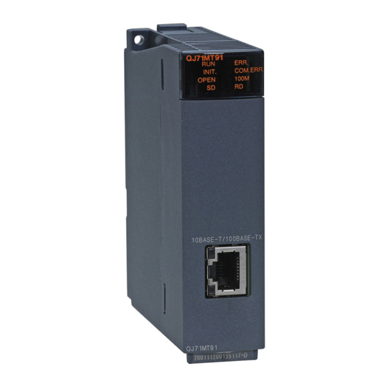
Page 81: Part Names
PRE-OPERATIONAL PROCEDURES AND SETTING MELSEC-Q 6.3 Part Names This section indicates the names of the QJ71MT91 parts. Name Description Indicator LEDs Refer to the following section, (1) Indications of indicator LEDs. Connector for connection of the QJ71MT91 to 10BASE- 10BASE/T/100BASE-TX T/100BASE-TX. - Page 82 PRE-OPERATIONAL PROCEDURES AND SETTING MELSEC-Q (1) Indications of indicator LEDs QJ71MT91 ERR. INIT. COM.ERR. OPEN 100M LED Name Indication Operation status Normal Error Normal completion of basic Basic parameter setting in INIT. Initial processing status parameter setting progress or nonexistent...
-
Page 83: Connection To Ethernet
PRE-OPERATIONAL PROCEDURES AND SETTING MELSEC-Q 6.4 Connection to Ethernet This section explains how to connect the QJ71MT91 to the 100BASE-TX or 10BASE-T network. (1) Connection precautions The following are the precautions for connection of the QJ71MT91. Handle the QJ71MT91 correctly, paying full attention to safety. - Page 84 (Step 2) Connect the twisted pair cable to the QJ71MT91. POINT (1) The QJ71MT91 detects whether 10BASE-T or 100BASE-TX, and the full or half duplex communication mode is used according to the hub. For connection with the hub that does not support the auto negotiation function, set the half duplex communication mode on the hub side.
-
Page 85: Unit Tests
QJ71MT91 (Refer to Section 6.6). 6.5.1 Hardware test The RAM and ROM of the QJ71MT91 are tested in the following steps. The test result can be checked with the LEDs on the front of the QJ71MT91. LED Status Step... -
Page 86: Self-Loopback Test
The procedure for the self-loopback test is shown below. This test is run for about 5 seconds. The test result can be checked with the LEDs on the front of the QJ71MT91. LED Status Step Operation [RUN] [OPEN] [ERR.]... -
Page 87: Intelligent Function Module Switch Setting
3. Click the <<I/O assignment>> tab and click the [Switch setting] button. The "Switch setting for I/O and intelligent function module" screen is displayed. [Operation procedure] 1. I/O assignment setting screen Set the following to the slot where the QJ71MT91 is mounted. Type : Select "Intelli". - Page 88 REMARK For the operation method of GX Developer, refer to the GX Developer Operating Manual. (1) Operation mode setting (Switch 1) Set the operation mode of the QJ71MT91, such as the online or offline mode. Set value Item Description Normal operation mode. Communicates with the target...
- Page 89 The QJ71MT91 starts up with its default basic parameters, and starts communication. [When corresponding bit is ON] The QJ71MT91 starts up with the basic parameters set using a sequence program or GX Configurator-MB, and starts communication. However, the user-set basic parameters are not registered to the QJ71MT91 until the following operation is performed.
- Page 90 Refer to Section 6.6.1 for details of the communication starting conditions of this switch setting and each function. (c) Online change enable/disable setting (Bit 2) Set whether to enable or disable the slave (QJ71MT91) to write data to the programmable controller CPU while the programmable controller CPU is in RUN status.
- Page 91 PRE-OPERATIONAL PROCEDURES AND SETTING MELSEC-Q (d) Send frame specification (Bit 3) Specify the frame format in which the QJ71MT91 will send data to the target device. [When corresponding bit is OFF] Data are sent in the Ethernet (V2.0)-compliant frame. [When corresponding bit is ON] Data are sent in the IEEE 802.3-compliant frame.
- Page 92 PRE-OPERATIONAL PROCEDURES AND SETTING MELSEC-Q (4) Redundant settings (Switch 5) When the redundant system is used, set the conditions of a system switching. 0: Fixed IP mode 1: Redundant IP mode 1: A mode for which IP addresses are fixed to system A and system B. 2: A mode for which IP addresses are switched according to a system switching of the control system and standby system.
-
Page 93: Communication Starting Conditions Depending On Basic Parameter/Modbus Device Assignment Parameter Starting Method Setting
PRE-OPERATIONAL PROCEDURES AND SETTING MELSEC-Q 6.6.1 Communication starting conditions depending on basic parameter/MODBUS device assignment parameter starting method setting The communication starting conditions change depending on the combination of the basic parameter and MODBUS device assignment parameter starting methods in Switch 2 of the intelligent function module switch setting. - Page 94 PRE-OPERATIONAL PROCEDURES AND SETTING MELSEC-Q (2) When sequence program is used for parameter setting When the basic parameter starting method is OFF (start with the default parameters) and the MODBUS device assignment parameter starting method is OFF (start with the default parameters) [Intelligent function module switch setting] [Communication starting conditions] 6 - 17...
- Page 95 PRE-OPERATIONAL PROCEDURES AND SETTING MELSEC-Q (b) When the basic parameter starting method is ON (start with the user-set parameters) and the MODBUS device assignment parameter starting method is OFF (start with the default parameters) [Intelligent function module switch setting] [Communication starting conditions] 6 - 18 6 - 18...
- Page 96 PRE-OPERATIONAL PROCEDURES AND SETTING MELSEC-Q (c) When the basic parameter starting method is OFF (start with the default parameters) and the MODBUS device assignment parameter starting method is ON (start with the user-set parameters) [Intelligent function module switch setting] [Communication starting conditions] 6 - 19 6 - 19...
- Page 97 PRE-OPERATIONAL PROCEDURES AND SETTING MELSEC-Q (d) When the basic parameter starting method is ON (start with the user-set parameters) and the MODBUS device assignment parameter starting method is ON (start with the user-set parameters) [Intelligent function module switch setting] [Communication starting conditions] 6 - 20 6 - 20...
-
Page 98: Parameter Setting
Refer to Chapter 9 for details. (c) Setting with GX Works2 Add the QJ71MT91 to the data of the intelligent function module in GX Works2 for the settings. For how to operate the data of an intelligent function module, refer to the GX Works2 Version 1 Operating Manual (Intelligent Function Module). - Page 99 PARAMETER SETTING MELSEC-Q (3) Parameter setting procedures Set the parameters in the following procedures. 7 - 2 7 - 2...
- Page 100 PARAMETER SETTING MELSEC-Q The X signal status can be confirmed using GX Configurator-MB. (Refer to Section 8.6.) 7 - 3 7 - 3...
- Page 101 PARAMETER SETTING MELSEC-Q 7 - 4 7 - 4...
- Page 102 PARAMETER SETTING MELSEC-Q 7 - 5 7 - 5...
-
Page 103: Basic Parameters
PARAMETER SETTING MELSEC-Q 7.2 Basic Parameters 7.2.1 Basic parameters details The basic parameters are classified into the following three types. (1) TCP/UDP/IP setting Address Parameter Name Setting Range Initial Value 0000 TCP ULP timer value 2 to 2400 Set time = set value × 500ms 0001 TCP zero window timer value 2 to 2400... -
Page 104: Gx Developer Connection Information Setting
PARAMETER SETTING MELSEC-Q (2) GX Developer connection information setting Address Parameter Name Setting Range Initial Value 0030 Number of TCP connections for GX Developer connection 0 to 8 (48) (3) MODBUS/TCP setting Address Parameter Name Setting Range Initial Value 1 to 4999, 0110 Local slave station port No. - Page 105 IP level due to the send/receive station buffer limitations. Set the time for waiting for the next split data segment in the case where the QJ71MT91 receives and restores the split data. No setting is required when the initial value is used.
- Page 106 TCP/UDP level are received. No setting is required when the default value is used. REMARK Specify the QJ71MT91 side timer values that will satisfy the following conditions. Automatic Split reception...
- Page 107 (e.g. via a dial-up router) and the TCP split transmission count is as described below. When QJ71MT91 transmission message size ≤ 536 bytes, n = 1 When 536 bytes < QJ71MT91 transmission message size ≤ 1072 bytes, n = 2 When 1072 bytes <...
- Page 108 PARAMETER SETTING MELSEC-Q (2) KeepAlive function (a) KeepAlive Set whether the KeepAlive function will be used or not. Setting name Setting Not used KeepAlive function is not used Used KeepAlive function is used No setting is required when the default value is used. (b) KeepAlive start timer value Set the time interval from the stop of communication with the target device to the start of alive check for the TCP connection opened with...
- Page 109 (a) Router relay function Set whether the router relay function will be used or not. The router relay function is not needed when the QJ71MT91 communicates with the target device on the same Ethernet (the subnet address of the IP address is the same).
- Page 110 QJ71MT91 differs from that of the target device. Set the subnet address of the target device when the class (network address) of the local station QJ71MT91 is the same as that of the target device. 7 - 13...
- Page 111 IP address: 81052902 (129.4.64.1) (113.4.64.1) (129.5.41.2) (Setting example 1) When the network addresses of the local station QJ71MT91 and target device differ Network address Local station QJ71MT91 IP address (Class B) 1 0 0 0 0 0 0 1 0 0 0 0 0 1 0 1...
- Page 112 PARAMETER SETTING MELSEC-Q (Setting example 3) When the network addresses of the local station QJ71MT91 and target device are the same Network address Local station QJ71MT91 IP address (Class B) 1 0 0 0 0 0 0 1 0 0 0 0 0 1 0 1...
- Page 113 PARAMETER SETTING MELSEC-Q 7.2.3 GX Developer connection information setting (1) Number of TCP connections for GX Developer connection TCP connections for GX Developer connection represents connections for connecting GX Developer using the TCP protocol. Set the desired number to the Number of TCP connections for GX Developer connection.
- Page 114 MELSEC-Q 7.2.4 MODBUS/TCP setting (1) Local slave station port No. Set the port No. on the QJ71MT91 side for receiving a request message from the master using the slave function of the QJ71MT91. POINT (1) The specifications of the MODBUS/TCP protocol define that "502" should be used as the port No.
- Page 115 *1: Refer to Section 11.3.3 for details of the error code. *2: Refer to Section 11.3.2 for details of the exception code. POINT When the CPU response monitoring timer value is "0ms", the QJ71MT91 waits until the programmable controller CPU completes processing. (Limitless waiting) (4) Preferred node specification...
-
Page 116: Automatic Communication Parameters
0 to 65535 (515) Set time = set value 10ms 0,2 to 2400 0204 Response monitoring timer value When the set value is 0, the QJ71MT91 (516) Set time = set value 500ms operates at 60 (30s). 0000 : Not specified... - Page 117 The initial value is "0". When the repeat interval timer value is "0", the QJ71MT91 will issue a next request message immediately after it has received a response message from the slave.
- Page 118 PARAMETER SETTING MELSEC-Q (5) Type specification of the target MODBUS device (a) Set the type of the read/write target MODBUS device. b8 b7 Read target Write target Set Value Target MODBUS Device Type Not specified Coil Input Input register Holding register (b) Setting range The following table gives the combinations of read and write targets available for the target MODBUS device type setting.
- Page 119 Head buffer memory Target MODBUS device Access points target MODBUS device address head number 0200 (Input) 1000 16628 <QJ71MT91 buffer memory> <Target slave device area> 116629 Read 1000 116640 to 116625 1001 116656 to 116641 1002 116672 to 116657 116663 Remaining area is masked with 0.
-
Page 120: Modbus Device Assignment Parameters
PARAMETER SETTING MELSEC-Q 7.4 MODBUS Device Assignment Parameters Using MODBUS device assignment parameters, the MODBUS devices are correlated with the programmable controller CPU device memory. This allows direct access from the MODBUS compatible master device to the programmable controller CPU device memory. 7 - 23 7 - 23... - Page 121 PARAMETER SETTING MELSEC-Q [Schematic image of MODBUS device assignment parameter setting] 7 - 24 7 - 24...
-
Page 122: Modbus Device Sizes
PARAMETER SETTING MELSEC-Q 7.4.1 MODBUS device sizes The MODBUS devices available for the QJ71MT91 are given in the following table. MODBUS Device Type Read/Write Access Points MODBUS Device Number Coil Read/Write 65536 points 000001 to 065536 Input Read 65536 points... -
Page 123: Modbus Device Assignment Parameters Details
PARAMETER SETTING MELSEC-Q 7.4.2 MODBUS device assignment parameters details Default Address Parameter Name Setting Range Value 0900 0000 : Device code not assigned Device code (2304) Other than 0000 : Device code 0901 Head device number 0000 to FFFF (2305) Coil assignment 1 (*1) 0902... - Page 124 *2: Refer to Section 7.4.5 for device assignment to the QJ71MT91 buffer memory. *3: Only this device is supported when the QJ71MT91 is mounted on a MELSECNET/H remote I/O station. An error will occur if an access request is received from the MODBUS/TCP master with any other device assigned.
- Page 125 The head MODBUS device number must not be duplicated in assignment 1 to 16. Set different head MODBUS device numbers. The slave function of the QJ71MT91 is inactive if any of the device number settings are duplicated. (4) Assignment points...
-
Page 126: Default Assignment Parameters
Refer to Section 6.6 for details of the intelligent function module switches. The following shows how the MODBUS devices are assigned by the MODBUS device assignment parameters and the default assignment parameter values set to the QJ71MT91 buffer memory. [Assignment of MODBUS devices by default assignment parameters] Coil... - Page 127 PARAMETER SETTING MELSEC-Q [Set values of default assignment parameters] Default Assignment Parameter Setting Items Buffer Memory Assignment Name Device code Head device Head MODBUS Assignment Address (Device symbol) number device number (*1) points Coil assignment 1 0900 to 0903 009D 0000 8192 Coil assignment 2...
-
Page 128: Modbus Extended File Register Assignment
For details, refer to the QCPU user's manual (explanation, program fundamentals). POINT Even if the slave (QJ71MT91) receives Write File Record (FC: 21) when the programmable controller CPU’s file register (ZR) is read-only (for example, when stored on a Flash card), it will issue a normal response. -
Page 129: Qj71Mt91 Buffer Memory Assignment
MELSEC-Q 7.4.5 QJ71MT91 buffer memory assignment (1) QJ71MT91 buffer memory assignment The QJ71MT91 can assign the MODBUS devices to the QJ71MT91 buffer memory. By making this assignment, access to the MODBUS devices will not be influenced by the sequence scan. - Page 130 POINT The programmable controller CPU device memory value can be stored in the QJ71MT91 buffer memory, and the QJ71MT91 buffer memory value can be stored in the programmable controller CPU device memory. Data can be stored by either of the following: Automatic refresh setting on GX Configurator-MB (Refer to Section 8.5)
-
Page 131: Utility Package (Gx Configurator-Mb)
Auto refresh setting Section 8.5 User free area (2) The data of the QJ71MT91 buffer memory areas set for auto refresh are automatically read from/written to the specified devices when the END instruction of the CPU module is executed. (1) Monitor/test The buffer memory and I/O signals of the QJ71MT91 are monitored or tested. -
Page 132: Installing And Uninstalling The Utility Package
UTILITY PACKAGE (GX Configurator-MB) MELSEC-Q 8.2 Installing and Uninstalling the Utility Package For how to install or uninstall the utility package, refer to "Method of installing the MELSOFT Series" included in the utility package. 8.2.1 Handling precautions The following explains the precautions on using the GX Configurator-MB. (1) For safety Since GX Configurator-MB is add-in software for GX Developer, read "Safety Precautions"... - Page 133 The number of parameters that can be set for one module in GX Configurator- MB is as shown below. Target module Initial setting Auto refresh setting QJ71MT91 3 (Fixed) 5 (Max.) Example) Counting the number of parameter settings in Auto refresh setting This one row is counted as one setting.
-
Page 134: Operating Environment
UTILITY PACKAGE (GX Configurator-MB) MELSEC-Q 8.2.2 Operating environment This section describes the operating environment of the personal computer that runs GX Configurator-MB. Item Description Installation (add-in) target GX Developer Version 4 (English version) or later. Personal computer Personal computer running one of the following operating systems Refer to the next page "Operating system and performance required for personal computer". - Page 135 UTILITY PACKAGE (GX Configurator-MB) MELSEC-Q Operating system and performance required for a personal computer Performance required for a personal computer Operating system Required memory Windows 95 Pentium 133MHz or more 32MB or more Windows 98 Pentium 133MHz or more 32MB or more Windows Me Pentium 150MHz or more 32MB or more...
-
Page 136: Utility Package Operation
UTILITY PACKAGE (GX Configurator-MB) MELSEC-Q 8.3 Utility Package Operation 8.3.1 Common utility package operations (1) Control keys Special keys that can be used for operation of the utility package and their applications are shown in the table below. Application Cancels the current entry in a cell. Closes the window. - Page 137 UTILITY PACKAGE (GX Configurator-MB) MELSEC-Q (2) Data created with the utility package The following data or files that are created with the utility package can be also handled in GX Developer. Figure 8.1 shows respective data or files are handled in which operation.
- Page 138 UTILITY PACKAGE (GX Configurator-MB) MELSEC-Q <Text files> A text file can be created by clicking the Make text file button on the initial setting, Auto refresh setting, or Monitor/Test screen. The text files can be utilized to create user documents. GX Developer/ Disk GX Configurator-MB...
-
Page 139: Operation Overview
UTILITY PACKAGE (GX Configurator-MB) MELSEC-Q 8.3.2 Operation overview GX Developer screen [Tools] - [Intelligent function utility] - [Start] Select a target intelligent function module screen Enter "Start I/O No." and select "Module type" and "Module model name". Refer to Section 8.3.3 Initial setting Auto refresh Initial setting screen... - Page 140 UTILITY PACKAGE (GX Configurator-MB) MELSEC-Q [Online] - [Monitor/Test] Select monitor/test module screen Select the module to be monitored/tested. Monitor/Test screen Refer to Section 8.6 8 - 10 8 - 10...
-
Page 141: Starting The Intelligent Function Module Utility
UTILITY PACKAGE (GX Configurator-MB) MELSEC-Q 8.3.3 Starting the Intelligent function module utility [Operating procedure] Intelligent function module utility is started from GX Developer. [Tools] → [Intelligent function utility] → [Start] [Setting Screen] [Explanation of items] (1) Activation of other screens Following screens can be displayed from the intelligent function module utility screen. - Page 142 (b) Set a target programmable controller CPU in GX Developer [Online] → [Transfer Setup] Only use the control CPU for the QJ71MT91 to write the intelligent function module parameters for a multiple CPU system to the programmable controller.
-
Page 143: Initial Setting
UTILITY PACKAGE (GX Configurator-MB) MELSEC-Q 8.4 Initial Setting [Purpose] Set parameters on the initial setting screen. This setting eliminates the need for parameter setting by sequence programs. The initial setting are as follows. Basic parameters Automatic communication parameters MODBUS device assignment parameters [Operating procedure] "Start I/O No."... - Page 144 CPU is reset (with the programmable controller CPU's RUN/STOP switch set to RUN). If the QJ71MT91 is mounted on a MELSECNET/H remote I/O station, the initial settings become effective when the remote I/O station receives the information notifying the status change (from STOP to RUN) of the remote master station's programmable controller CPU.
-
Page 145: Auto Refresh Setting
MELSEC-Q 8.5 Auto Refresh Setting [Purpose] Make this setting to store the QJ71MT91 buffer memory data into the specified devices of the programmable controller CPU or to store the programmable controller CPU device data into the QJ71MT91 buffer memory automatically. - Page 146 UTILITY PACKAGE (GX Configurator-MB) MELSEC-Q (b) Display items 1) Module side Buffer size Displays the buffer memory size of the setting item. 2) Module side Transfer word count Displays the number of words to be transferred. 3) Module side buffer offset Displays the offset value of the buffer memory data to be transferred.
-
Page 147: Monitor/Test
From this screen, start the monitoring or test of the operating status, I/O signals, parameter setting status, automatic communication status, error log, communication status of the QJ71MT91 and perform PING test. [Operating procedure] Select monitor/test module screen → "Start I/O No. *" → "Module type" →... - Page 148 UTILITY PACKAGE (GX Configurator-MB) MELSEC-Q Buffer memory Reference Monitor/Test Items address section INIT. status OPEN status 0C05 Module status LED ON status Section 11.2 (3077) ERR. status COM. ERR. status COM. ERR. LED OFF request (*1) Section 11.4.1 X/Y Monitor/test (*2) Section 8.6.1 Basic/MODBUS device assignment parameter status (*2) Section 8.6.2...
- Page 149 UTILITY PACKAGE (GX Configurator-MB) MELSEC-Q [Monitor/Test screen - Sub screen shift] Refer to Section 8.6.2 Basic/MODBUS(R) device X/Y Monitor/test Automatic communication Refer to Section 8.6.1 Refer to Section 8.6.3 8 - 19 8 - 19...
- Page 150 UTILITY PACKAGE (GX Configurator-MB) MELSEC-Q Refer to Section 8.6.4 Error log Communication status PING test Refer to Section 8.6.5 Refer to Section 8.6.6 8 - 20 8 - 20...
-
Page 151: X/Y Monitor/Test
UTILITY PACKAGE (GX Configurator-MB) MELSEC-Q 8.6.1 X/Y Monitor/test [Monitor/Test Purpose] Monitor I/O signals and performs tests on output signals. [Operating procedure] Monitor/Test screen → X/Y Monitor/test [Monitor/Test Screen] [Monitor/Test Items] (1) X: Input signals Buffer memory Reference Monitor/Test Item address section X00: Module READY X01: Basic parameter setting, normally completed... - Page 152 UTILITY PACKAGE (GX Configurator-MB) MELSEC-Q (2) Y: Output signals To perform a test on output signals, select any item in the Setting value column and click the Execute test button. Buffer memory Reference Monitor/Test Item address section Y01: Basic parameter setting request Y04: Automatic communication parameter setting request/automatic communication start request Y06: Automatic communication stop request...
-
Page 153: Basic/Modbus Device Assignment Parameter Status
UTILITY PACKAGE (GX Configurator-MB) MELSEC-Q 8.6.2 Basic/MODBUS device assignment parameter status [Monitor Purpose] Monitor the setting status of the basic parameters and MODBUS device assignment parameters. [Operating procedure] Monitor/Test screen → Basic/MODBUS device [Monitor Screen] [Monitor Items] Buffer memory Reference Monitor Item address section... -
Page 154: Automatic Communication Status
UTILITY PACKAGE (GX Configurator-MB) MELSEC-Q 8.6.3 Automatic communication status [Monitor/Test Purpose] Monitor the communication status of the automatic communication function. [Operating procedure] Monitor/Test screen → Automatic communication [Monitor/Test Screen] [Monitor/Test Items] Buffer memory Reference Monitor/Test Item address section Automatic communication operation status Section 5.2.1 0C11 Automatic communication parameter error code storage area... - Page 155 UTILITY PACKAGE (GX Configurator-MB) MELSEC-Q *1: To test the automatic communication start request or automatic communication stop request, select the corresponding item in the Setting column and click the Execute test button. value POINT When conducting a test on the automatic communication start request or automatic communication stop request with "Being requested"...
-
Page 156: Error Log
MELSEC-Q 8.6.4 Error log [Monitor Purpose] Display the errors that occurred in the QJ71MT91. Error logs are displayed in reverse chronological order (the latest error is displayed as No.1). For details of the monitoring items, refer to Section 11.3.1 (8), (b) Number of error occurred and (d) Error log (error log 1 to 32). -
Page 157: Communication Status
UTILITY PACKAGE (GX Configurator-MB) MELSEC-Q 8.6.5 Communication status [Monitor Purpose] Monitor the communication status by communication protocol. [Operating procedure] Monitor/Test screen → Communication status [Monitor Screen] [Monitor Items] Buffer memory Reference Monitor Item address section 0E10 to 0E11 IP packet reception count (3600 to 3601) 0E12 to 0E13... - Page 158 UTILITY PACKAGE (GX Configurator-MB) MELSEC-Q Buffer memory Reference Monitor Item address section 0E30 to 0E31 ICMP packet reception count (3632 to 3633) Count of ICMP packet reception discarded due to sum check 0E32 to 0E33 error (3634 to 3635) 0E34 to 0E35 Total number of sent ICMP packets (3636 to 3637)
-
Page 159: Ping Test
UTILITY PACKAGE (GX Configurator-MB) MELSEC-Q 8.6.6 PING test [Monitor/Test Purpose] Display the execution and result of a PING test. Refer to Section 11.5 for details. [Operating procedure] Monitor/Test screen → PING test [Monitor/Test Screen] [Monitor/Test Items] Buffer memory Reference Monitor/Test Item address section 0FE0... -
Page 160: Parameter Setting Using Gx Configurator-Mb
UTILITY PACKAGE (GX Configurator-MB) MELSEC-Q 8.7 Parameter Setting Using GX Configurator-MB 8.7.1 Basic parameters [Purpose] Set the basic parameters on the basic parameter screen. [Operating procedure] Initial setting screen → Basic parameter [Setting screen] 8 - 30 8 - 30... - Page 161 UTILITY PACKAGE (GX Configurator-MB) MELSEC-Q [Setting items] For the basic parameter setting, set the data format or setting range value of each item in the Setting value column, and click the End setup button to save the set values. Buffer memory Reference Setting Item address...
- Page 162 UTILITY PACKAGE (GX Configurator-MB) MELSEC-Q Buffer memory Reference Setting Item address section 0110 Local slave station port No. (272) Target slave port No. for automatic 0111 communication function (273) TCP/UDP/ MODBUS/TCP 0114 Section 7.2 IP setting setting CPU response monitoring timer value (276) Preferred node specification 1 to 64 0115...
-
Page 163: Automatic Communication Parameters
UTILITY PACKAGE (GX Configurator-MB) MELSEC-Q 8.7.2 Automatic communication parameters [Purpose] Set the automatic communication parameters on the Automatic communication parameter screen. [Operating procedure] Initial setting screen → Automatic communication parameter [Setting screen] 8 - 33 8 - 33... - Page 164 UTILITY PACKAGE (GX Configurator-MB) MELSEC-Q [Setting items] For the automatic communication parameter setting, set the data format or setting range value of each item in the Setting value column, and click the End setup button to save the set values. Buffer memory Reference Setting Item...
-
Page 165: Modbus Device Assignment Parameters
UTILITY PACKAGE (GX Configurator-MB) MELSEC-Q 8.7.3 MODBUS device assignment parameters [Purpose] Set the MODBUS device assignment parameters on the MODBUS device assignment parameter screen. [Operating procedure] Initial setting screen → MODBUS device assignment [Setting screen] 8 - 35 8 - 35... - Page 166 5FFF ) setting When the MODBUS device is the input register or holding register, the QJ71MT91 buffer memory (user free area) setting is available. For setting, enter a value as a hexadecimal constant as shown below. Example) 5000 Enter a value "H5000".
-
Page 167: Programming
When applying the following program examples to the actual system, make sure to examine the applicability and confirm that it will not cause system control problems. On-screen parameter setting for the QJ71MT91 is available by use of the utility package (GX Configurator-MB), reducing sequence programs. Refer to Chapter 8 for details of the utility package (GX Configurator-MB) operation method. - Page 168 Basic parameter setting existence Basic parameter Error code 0C10 clear error code storage Executed by QJ71MT91 area Executed by sequence program (b) When setting is completed with an error Basic parameter Basic parameter setting, error setting, normally completed...
- Page 169 PROGRAMMING MELSEC-Q (4) Precautions for basic parameter setting When setting the basic parameters with a sequence program, set the basic parameter starting method (b0) of the intelligent function module switch 2 (refer to Section 6.6) to ON (Start with the user-set parameters). Turn ON Basic parameter setting request (Y1) after Module READY (X0) has turned ON.
-
Page 170: Automatic Communication Parameter Setting
PROGRAMMING MELSEC-Q 9.1.2 Automatic communication parameter setting (1) Automatic communication parameter setting method Make automatic communication parameter setting in the following procedure. 1) Store the parameters into the automatic communication parameter area (address: 0200 to 04FF ) of the buffer memory. 2) Turn ON Automatic communication parameter setting request/automatic communication start request (Y4). - Page 171 Error code storage area and setting result clear Automatic communication 0C12 parameter setting result Executed by QJ71MT91 storage area Executed by sequence program (b) When setting is completed with an error Automatic communication Automatic communication parameter setting, normally parameter setting, error...
- Page 172 Identify the stored parameter, check its error code, take corrective action, and make a parameter setting request again. Refer to Section 11.3 for details of the error code. (c) The QJ71MT91 does not clear the automatic communication function buffer input area (address: 1000 to 1FFF...
-
Page 173: Modbus Device Assignment Parameter Setting
PROGRAMMING MELSEC-Q 9.1.3 MODBUS device assignment parameter setting (1) MODBUS device assignment parameter setting method Make MODBUS device assignment parameter setting in the following procedure. 1) Store the parameters into the MODBUS device assignment parameter area (address: 0900 to 09FF ) of the buffer memory. - Page 174 PROGRAMMING MELSEC-Q (3) Timing charts for MODBUS device assignment parameter setting (a) When setting is completed normally 9 - 8 9 - 8...
- Page 175 PROGRAMMING MELSEC-Q (b) When setting is completed with an error 9 - 9 9 - 9...
- Page 176 Set the MODBUS device assignment parameters in the online mode (intelligent function module switch 1: 0000 (f) The QJ71MT91 sends an exception response to the master if it receives a MODBUS device data read/write request message from the master before the MODBUS device assignment parameters are set normally.
-
Page 177: Program Example For Normal System Configuration
A program will be explained as an example to realize the following specifications for the setting target QJ71MT91 (192.1.0.1). 1: This QJ71MT91 is assumed to be mounted in Slot 0 of the base unit with the head I/O No. set to 0. - Page 178 PROGRAMMING MELSEC-Q (a) Automatic communication function The setting target QJ71MT91 (192.1.0.1) and MODBUS/TCP slave device (192.1.0.2) communicate with each other using the automatic communication function. Set automatic communication parameters to the setting target QJ71MT91. [Communication details] 9 - 12 9 - 12...
- Page 179 PROGRAMMING MELSEC-Q (b) MODBUS device assignment function The setting target QJ71MT91 (192.1.0.1) uses the MODBUS device assignment function. Set the MODBUS device assignment parameters to the setting target QJ71MT91. [Assignment details] 9 - 13 9 - 13...
- Page 180 PROGRAMMING MELSEC-Q (2) Parameter setting details The following table gives the setting details of the parameters set in the program example. (a) Basic parameters Setting Item Buffer Memory Address Set Value TCP ULP timer value 0000 60 (30s) TCP zero window timer value 0001 20 (10s) TCP resend timer value...
- Page 181 PROGRAMMING MELSEC-Q (b) Automatic communication parameters Setting Item Buffer Memory Address Set Value C0010002 Target station IP address 0200 to 0201 (512 to 513) (192.1.0.2) Module ID 0202 (514) Repeat interval timer value 0203 (515) 1200(120s) Response monitoring timer value 0204 (516) 60(30s)
- Page 182 Basic parameter setting, error completed Basic parameter setting existence Input Automatic communication parameter setting, normally completed Automatic communication parameter setting, error completed QJ71MT91 Automatic communication operation status input/output MODBUS device assignment parameter setting, normally completed MODBUS device assignment parameter setting, error completed...
- Page 183 PROGRAMMING MELSEC-Q Device Name Device Application U0\G0 to U0\G19 U0\G48 U0\G272 to Basic parameter setting area U0\G273 U0\G276 to U0\G279 U0\G512 to U0\G520 U0\G524 to Automatic communication parameter setting area U0\G529 U0\G533 to U0\G535 U0\G2304 to U0\G2307 U0\G2432 to MODBUS device assignment parameter setting area U0\G2435 Intelligent function module U0\G2496 to...
-
Page 184: Program Using Utility Package
PROGRAMMING MELSEC-Q 9.2.2 Program using utility package (1) Intelligent function module switch setting Set the intelligent function module switches by clicking Switch setting on <<I/O assignment>> of GX Developer. For the program example, set intelligent function module switches as described below. - Page 185 PROGRAMMING MELSEC-Q (b) Automatic communication parameters Set the automatic communication parameters on the [Automatic communication parameter] screen. Set the values shown in Section 9.2.1 (2) (b). (c) MODBUS device assignment parameters Set the MODBUS device assignment parameters on the [MODBUS device assignment parameter] screen.
- Page 186 PROGRAMMING MELSEC-Q (3) Auto refresh setting Make auto refresh setting from the Auto refresh setting screen of GX Configurator-MB. Set the following items for the program example. Module side Module side PLC side Setting Item Transfer word count Buffer offset Device Automatic communication function buffer input area 256(100...
- Page 187 PROGRAMMING MELSEC-Q (5) Program example 9 - 21 9 - 21...
-
Page 188: Program Without Using Utility Package
PROGRAMMING MELSEC-Q 9.2.3 Program without using utility package (1) Intelligent function module switch setting Set the intelligent function module switches by clicking Switch setting on <<I/O assignment>> of GX Developer. For the program example, set intelligent function module switches as described below. - Page 189 PROGRAMMING MELSEC-Q (2) Parameter setting Set the parameters using a sequence program. Parameter setting can be omitted under the following conditions. Parameter Setting Omitting Condition Parameter Condition Setting method With the intelligent function module switch 2, set the basic parameter starting method (bit Basic parameters Use the default parameters.
- Page 190 PROGRAMMING MELSEC-Q (5) Program example <<Basic parameter setting>> TCP ULP timer value Parameter Module setting READY command TCP zero window timer value TCP resend timer value TCP end timer value IP reassembly timer value Split reception monitoring timer value KeepAlive KeepAlive start timer value KeepAlive interval timer value KeepAlive resend count...
- Page 191 PROGRAMMING MELSEC-Q Turns OFF Basic parameter Basic setting request (Y1) when parameter setting is completed normally. setting, normally completed Turns ON automatic communication parameter Parameter setting setting command. command Turns OFF Basic parameter Basic setting request (Y1) and stores parameter error code into D100 when setting, setting fails.
- Page 192 PROGRAMMING MELSEC-Q 9 - 26 9 - 26...
- Page 193 PROGRAMMING MELSEC-Q 9 - 27 9 - 27...
- Page 194 PROGRAMMING MELSEC-Q 9 - 28 9 - 28...
-
Page 195: Program Example For Use In Melsecnet/H Remote I/O Network
A program will be explained as an example to realize the following specifications for the setting target QJ71MT91 (192.1.0.1). 1 : This QJ71MT91 is assumed to be mounted in Slot 0 of the base unit with the head I/O No. set to "0". - Page 196 PROGRAMMING MELSEC-Q (a) Automatic communication function The setting target QJ71MT91 (192.1.0.1) and MODBUS/TCP slave device (192.1.0.2) communicate with each other using the automatic communication function. Set the automatic communication parameters to the setting target QJ71MT91. [Communication details] MELSECNET/H remote master station...
- Page 197 PROGRAMMING MELSEC-Q 9 - 31 9 - 31...
- Page 198 PROGRAMMING MELSEC-Q (b) MODBUS device assignment function The setting target QJ71MT91 (192.1.0.1) uses the MODBUS device assignment function. Set the MODBUS device assignment parameters to the setting target QJ71MT91. [Assignment details] Refer to Section 9.2.1 (1) (b) for the assignment details.
- Page 199 Basic parameter setting existence X1003 Input X1004 Automatic communication parameter setting, normally completed X1005 Automatic communication parameter setting, error completed QJ71MT91 X1006 Automatic communication operation status input/output X1008 MODBUS device assignment parameter setting, normally completed X1009 MODBUS device assignment parameter setting, error completed...
- Page 200 PROGRAMMING MELSEC-Q Device Name Device Application SB20 Module status Link special relay SB47 Baton pass status (host) SB49 Host data link status SW70.1 Baton pass status of each station Link special register SW74.1 Cyclic transmission status of each station SW78.1 Parameter communication status of each station Timer T0 to T4...
-
Page 201: Program Using Utility Package
PROGRAMMING MELSEC-Q 9.3.2 Program using utility package (1) Intelligent function module switch setting Set the intelligent function module switches by clicking Switch setting on <<I/O assignment>> of GX Developer. Refer to Section 9.2.2 (1) for the intelligent function module switches. (2) Parameter setting Set the parameters from the Initial setting screen of GX Configurator-MB. - Page 202 PROGRAMMING MELSEC-Q (4) Network parameter setting Set the network parameters on "Network parameter" of GX Developer. 1) Network type : MNET/H (remote master) 2) Starting I/O No. : 0000 3) Network No. 4) Total number of (slave) stations 5) Mode : Online 6) Network range assignment XY setting...
- Page 203 PROGRAMMING MELSEC-Q (6) Program example (a) Interlock program example for remote master station and remote I/O station Provide interlocks depending on the link status of the remote master station (local station) and remote I/O station (other station). The following example shows communication program interlocks using the link status (SB47, SB49) of the remote master station and the link status (SW70 bit 0, SW74 bit 0, SW78 bit 0) of the remote I/O station (station No.
- Page 204 PROGRAMMING MELSEC-Q (b) Program example for automatic communication function POINT After execution of the REMTO/REMFR instruction, it requires several scans until read/write of actual data is completed. 9 - 38 9 - 38...
-
Page 205: Program Without Using Utility Package
PROGRAMMING MELSEC-Q 9.3.3 Program without using utility package (1) Intelligent function module switch setting Set the intelligent function module switches by clicking Switch setting on <<I/O assignment>> of GX Developer. Refer to Section 9.2.3 (1) for the intelligent function module switches. (2) Parameter setting Set the parameters using a sequence program. - Page 206 PROGRAMMING MELSEC-Q (3) Network parameter setting Set the network parameters on "Network parameter" of GX Developer. 1) Network type : MNET/H (remote master) 2) Starting I/O No. : 0000 3) Network No. 4) Total number of (slave) stations 5) Mode : Online 6) Network range assignment XY setting...
- Page 207 PROGRAMMING MELSEC-Q (6) Program example (a) Interlock program example for remote master station and remote I/O station Provide interlocks depending on the link status of the remote master station (local station) and remote I/O station (other station). The following example shows communication program interlocks using the link status (SB47, SB49) of the remote master station and the link status (SW70 bit 0, SW74 bit 0, SW78 bit 0) of the remote I/O station (station No.
- Page 208 Default router IP address Number of routers set Subnet address Router IP address Number of TCP connections for GX Developer connection Transfers basic parameters to REMTO QJ71MT91 buffer memory. instruction completion Turns ON Basic parameter REMTO REMTO setting command (M200) when Parameter...
- Page 209 MELSEC-Q Local slave station port No. Parameter setting command Target slave port No. for automatic communication function Transfers basic parameters to REMTO QJ71MT91 buffer memory. instruction completion Turns ON Basic parameter setting REMTO REMTO Parameter command (M400) when instruction instruction setting ZP.REMTO instruction is...
- Page 210 PROGRAMMING MELSEC-Q 9 - 44 9 - 44...
- Page 211 PROGRAMMING MELSEC-Q 9 - 45 9 - 45...
- Page 212 PROGRAMMING MELSEC-Q 9 - 46 9 - 46...
- Page 213 PROGRAMMING MELSEC-Q 9 - 47 9 - 47...
- Page 214 PROGRAMMING MELSEC-Q 9 - 48 9 - 48...
- Page 215 PROGRAMMING MELSEC-Q 9 - 49 9 - 49...
-
Page 216: Dedicated Instructions
The dedicated instructions make programming easy for use of the intelligent function module functions. 10.1 Dedicated Instruction List and Available Devices (1) Dedicated instruction list The following table indicates a list of dedicated instructions supported by the QJ71MT91. Dedicated Description Reference Instruction... -
Page 217: Z(P).Mbrw
DEDICATED INSTRUCTIONS MELSEC-Q 10.2 Z(P).MBRW With this instruction, the MODBUS device data are read from and written to the slave. Usable Devices Internal device Link direct device Intelligent Constant Set Data (System, user) J \ function module Index register File register Others device... - Page 218 DEDICATED INSTRUCTIONS MELSEC-Q Control data Setting Setting Device Item Set Data Side Range 1) Close option (Bit 0) Set whether a TCP connection will be closed or not after instruction (S1)+0 Execution type 0, 1 User completion. 0: TCP connection is not closed after instruction completion. 1: TCP connection is closed after instruction completion.
- Page 219 DEDICATED INSTRUCTIONS MELSEC-Q Setting Setting Device Item Set Data Side Range Specify the file number when the target MODBUS device is the extended file Correspond- 0 to 65535 (S1)+9 User (*3, *4) register. ing file number Specify the head number of the read target MODBUS device. Target As the device head number, specify the lower 5 digits of "(actual device number) - 1".
- Page 220 DEDICATED INSTRUCTIONS MELSEC-Q Set "0" for the case of write only. Set "0" for the case of read only. The combinations of the read and write targets that can be set in the target MODBUS device type setting and the setting ranges of the access points are as indicated in the following table.
- Page 221 Create a sequence program carefully so that the number of simultaneously executed MBRW instructions does not exceed 8. The QJ71MT91 automatically opens a TCP connection with a target slave when this instruction is executed. Whether TCP connection closing processing is performed or not can be selected in "Execution type ((S1)+0)"...
- Page 222 DEDICATED INSTRUCTIONS MELSEC-Q [Operation for MBRW instruction execution] processing processing processing processing Sequence program Completion of MBRW instruction execution MBRW instruction Completion device Error (D2) completion Normal Completion status completion indication device 1 scan (D2)+1 Error When the dedicated instruction is completed with an error, the completion status indication device (D2)+1 turns ON and the error code is stored into the complete condition (S1)+1.
- Page 223 Program example The following program is designed to read and write the device data in the holding register of the slave (IP address: 192.1.0.2). When the I/O signals of the QJ71MT91 are X/Y00 to X/Y1F 10 - 8 10 - 8...
- Page 224 DEDICATED INSTRUCTIONS MELSEC-Q 10 - 9 10 - 9...
- Page 225 DEDICATED INSTRUCTIONS MELSEC-Q REMARK The MODBUS/TCP frames used in communication with the slave in this sample program are as shown below. Request message format (Master (QJ71MT91) Slave) Function Data code Function Read head holding Read points Write head holding Write points...
-
Page 226: Z(P).Mbreq
DEDICATED INSTRUCTIONS MELSEC-Q 10.3 Z(P).MBREQ With this instruction, a request message can be sent to the slave in any given PDU (protocol data unit) format. Usable Devices Internal device Link direct device Intelligent Constant Set Data (System, user) J \ function module Index register File register... - Page 227 DEDICATED INSTRUCTIONS MELSEC-Q Control data Setting Setting Device Item Set Data Range Side 1) Close option (Bit 0) Set whether a TCP connection will be closed or not after instruction (S1)+0 Execution type 0, 1 User completion. 0: TCP connection is not closed after instruction completion. 1: TCP connection is closed after instruction completion.
- Page 228 DEDICATED INSTRUCTIONS MELSEC-Q Request message storing devices Setting Setting Device Item Set Data Side Range Request message (S2)+0 Set the size of the request message to be sent in byte units. 1 to 253 User size [byte] Set the contents (function code + data) of the request message to be sent. (Example) When a request message to read the data of holding registers 440001 to 440002 is sent by Read holding registers (FC: 03) <Frame of request message to be sent>...
- Page 229 DEDICATED INSTRUCTIONS MELSEC-Q Response message storing devices Setting Setting Device Item Set Data Side Range Response (D1)+0 message size Set the size of the received response message in byte units. 0 to 253 System [byte] Set the contents (function code + data) of the received response message. (Example) When the response message with Read holding registers (FC: 03) is received <Received response message frame>...
- Page 230 Create a sequence program so that the number of simultaneously executed MBREQ instructions does not exceed 8. The QJ71MT91 automatically opens a TCP connection with a target slave when this instruction is executed. Whether TCP connection closing processing is performed or not can be selected in "Execution type ((S1)+0)"...
- Page 231 0008 to the holding register 400003 (Mask write register (FC: 22) of the slave (IP address: 192.1.0.2). When the I/O signals of the QJ71MT91 are X/Y00 to X/Y1F (1) Operation of program example 10 - 16 10 - 16...
- Page 232 DEDICATED INSTRUCTIONS MELSEC-Q (2) Frames sent and received by MBREQ instruction Request message format (Master (QJ71MT91) → Slave) Function code Data Function code Target holding register number AND mask value OR mask value (0008 Sending order 7 bytes Response message format <When completed normally>...
- Page 233 DEDICATED INSTRUCTIONS MELSEC-Q Execution type Dedicated Module Basic instruction READY parameter start setting command existence Clears the complete condition to 0. Sets 0 (fixed). Target IP address Module ID (Station No.) Target slave port No. Response monitoring timer value Request message size Request message Dedicated instruction (Z.MBREQ) MBREQ...
-
Page 234: Troubleshooting
2 (communication condition Section 6.6 setting) value. Check the intelligent function module switch 3, 4 (IP address setting) value. Check if the QJ71MT91 is not mounted Mount the QJ71MT91 with the Q mode Section 2.1 with the A mode QCPU. QCPU. - Page 235 This section not flicker during executed.". (3)-1 data reception. When using slave function Refer to "Slave function of QJ71MT91 This section does not return response message to (3)-3 request message.". When using GX Developer connection Refer to "GX Developer cannot be This section connected.".
- Page 236 TROUBLESHOOTING MELSEC-Q (2) Troubleshooting of errors indicated by X signals Reference Symptom Check Item Corrective Action Section 1 Module READY Refer to "RUN LED turned off.". (X0) turned off. This section 2 Watch dog timer (1)-1 error (X1F) turned 3 Basic parameter Refer to the basic parameter error code Take the corresponding corrective action setting, error...
- Page 237 TCP connections to 2 to be connected to the QJ71MT91. 10 COM. ERR. LED Refer to "COM. ERR. LED turned on.". This section...
- Page 238 D? or later when communication Use SD1590 of the control system Has the QJ71MT91 issued a system error occurs. CPU module to check if the switching request to the control QJ71MT91 has issued a system system CPU module? switching request.
- Page 239 CPU module. Is the tracking cable connected Connect the tracking cable properly. properly? Has the QJ71MT91 issued a system Issue a system switching request to switching request to the standby the control system CPU module. system CPU module?
- Page 240 When dedicated instructions and the automatic communication function are executed simultaneously, change the settings of the target device and change the number of TCP connections to 2 to be connected to the QJ71MT91. 11 - 7 11 - 7...
- Page 241 Section 7.2 (The slave function stops when the basic parameters are re-set.) Check whether the QJ71MT91 has Confirm the exception code and take Section 11.3.2 returned an exception code or not. corrective action. Refer to the error log area (0CFE Take the corresponding corrective Section 11.3...
- Page 242 Set a MODBUS/TCP slave device as check if the communication target device the communication target. is a MODBUS/TCP slave device. When the QJ71MT91 is a slave, check if Set a MODBUS/TCP master device as the communication target device is a the communication target device.
- Page 243 Specify the nodes as preferred ones when necessary. • Reduce the number of simultaneously connected connections. Check whether the QJ71MT91 has If two or more send requests are issued, issued two or more send requests long time is required as they are concurrently.
- Page 244 Reconnect and retry. Specify the nodes as preferred ones when necessary. 9 Normal Check if the power was reapplied after Reapply the power of the QJ71MT91 or communication is replacement of the QJ71MT91 or target target device. not available after device.
-
Page 245: Confirming Qj71Mt91 Status
Refer to Section 8.6 for the Monitor/Test screen. (2) System monitor of GX Developer The module status of the QJ71MT91 can be confirmed from the system monitor. (a) When confirming the module status and error code on the Module's Detailed... - Page 246 * The alphabet at the end of the production information indicates the function version of the module. Function version of the QJ71MT91 is available from B. (Example) The product information that ends with "B" indicates that the module is of function version B.
- Page 247 [Starting Procedure] GX Developer → [Diagnostics] → [System monitor] → Module's Detailed Information → H/W Information [Display Data] The QJ71MT91 data stored in the following buffer memory areas are displayed. Display Data Corresponding Buffer Memory Area Address Left side of H/W LED Information...
-
Page 248: Error Codes
TROUBLESHOOTING MELSEC-Q 11.3 Error Codes 11.3.1 Error code storage areas The error code of each error is stored into any of the following buffer memory areas. Error Type Storage Area Name Address 0C10 Basic parameter Basic parameter error code storage area (3088) Automatic communication parameter error code 0C11... - Page 249 TROUBLESHOOTING MELSEC-Q (2) Automatic communication parameter error code storage area (a) When an error occurs with the automatic communication parameter setting request/automatic communication start request (Y4) ON, the corresponding error code is stored in this area. (b) The error code is stored when the automatic communication parameter setting, error completed (X5) turns ON.
- Page 250 Here is a program example. Program condition The QJ71MT91 is mounted in slot 0 of the base unit with the head I/O No. set to "0" and the automatic communication parameter 1 is used. Program example...
- Page 251 TROUBLESHOOTING MELSEC-Q (7) Automatic communication function error code storage area When an error occurs in the automatic communication function, the error code corresponding to the automatic communication parameter 1 to 64 is stored in this area. When the automatic communication function operation status bit turns ON, the error code is stored into the corresponding area.
- Page 252 TROUBLESHOOTING MELSEC-Q Error log (error log 1 to 32) • The error log area stores the 32 latest errors. • The error log area stores the errors in order of occurrence, starting from the error log 1. • If 33 or more errors have occurred, the error logs are overwritten, starting from the area of the error log 1.
- Page 253 TROUBLESHOOTING MELSEC-Q (9) Communication status of each protocol The numbers of corresponding events of each protocol are stored. Error Name of Each Protocol Address 0E10 to 0E11 IP packet reception count (3600 to 3601) 0E12 to 0E13 Count of IP packet reception discarded due to sum check error (3602 to 3603) 0E14 to 0E15...
-
Page 254: Exception Code List
(address: CFE to DFF ) of the buffer memory. (b) Exception code list The following is a list of exception codes used when the QJ71MT91 is a slave. Corrective Action Exception Error Name... - Page 255 (3) Error code for error completion of processing in slave (QJ71MT91) If the processing in the slave (QJ71MT91) results in error completion, an exception code is stored into the buffer memory. In the QJ71MT91, an error code is also stored into the buffer memory to identify the cause in detail.
-
Page 256: Error Code List
TROUBLESHOOTING MELSEC-Q 11.3.3 Error code list When an error occurs in any processing of the QJ71MT91, the error code is stored into its buffer memory. This section explains the error details and corrective actions to be taken at error occurrence. - Page 257 TROUBLESHOOTING MELSEC-Q Error Occurrence Error Name Description Lit LED Corrective Action Code After power-on with parameters preset by GX Configurator-MB, before Basic parameter setting existence (X3) turns on, When using parameters set by parameter settings were done GX Configurator-MB, do not by any of the following: Parameter make parameter settings by Y-...
- Page 258 TROUBLESHOOTING MELSEC-Q Error Occurrence Error Name Description Lit LED Corrective Action Code The number of TCP connections for GX Developer connection or the Review the setting of the Number of TCP total number of TCP number of TCP connections for 731A connections setting COM.ERR.
- Page 259 MODBUS device number and COM.ERR. assignment parameters are overlap error assignment points. overlapped. The assigned range of the QJ71MT91 buffer memory Buffer memory Review the setting of the head set with the MODBUS device 7333 assigned range device number and assignment COM.ERR.
- Page 260 TROUBLESHOOTING MELSEC-Q Error Occurrence Error Name Description Lit LED Corrective Action Code The setting range of the buffer memory in the Buffer memory automatic communication Correct the buffer memory 7346 address range parameter is outside the COM.ERR. setting outside the range. error range of the automatic communication function...
- Page 261 GX Configurator-MB at (Y4) after Basic parameter power-on. setting existence (X3) has turned on. When the QJ71MT91 on the Delete the automatic main base unit of a redundant communication parameter system is mounted, the setting. (When mounting the...
- Page 262 TROUBLESHOOTING MELSEC-Q Error Occurrence Error Name Description Lit LED Corrective Action Code In the automatic communication function or Protocol ID dedicated instruction, the 7363 COM.ERR. error protocol ID of the received response message is other than "0: MODBUS protocol". In the automatic communication function or dedicated instruction, the Module ID...
- Page 263 • The dedicated instruction basic parameters. cannot be executed due to • Execute the dedicated the offline mode. instruction in the online Dedicated • Since the QJ71MT91 on mode. instruction 737A the main base unit of a COM.ERR. • To use the dedicated...
- Page 264 TROUBLESHOOTING MELSEC-Q Error Occurrence Error Name Description Lit LED Corrective Action Code The range of the MODBUS device specified in the received request message exceeds the maximum Review the specified data of value* of the MODBUS the MODBUS device on the 7385 device.
- Page 265 • Check whether or not the operating environment of the system is within the range of general specifications of the CPU module. 739C The OS of the QJ71MT91 • Check whether the power System error COM.ERR. capacity is sufficient or not. detected error.
- Page 266 • Check whether or not the An error was detected in the 73C1 ROM error ERR. QJ71MT91, power supply ROM test. module and CPU module are mounted correctly on the base unit. • Check whether or not the...
- Page 267 73D0 the slave function of the COM.ERR. • Check the line status for an Response QJ71MT91 could not send a error. response message. message transmission As the TCP connection was • Check whether the operation...
- Page 268 TROUBLESHOOTING MELSEC-Q Error Occurrence Error Name Description Lit LED Corrective Action Code • Retry after a little while. • If this error occurs at execution Error during Transmission through the of the dedicated instruction, set "TCP connection is not closed 73D7 close connection being closed was...
- Page 269 TROUBLESHOOTING MELSEC-Q Error Occurrence Error Name Description Lit LED Corrective Action Code • Check whether the operation status of the target device is normal or not. 7404 A receive error occurred. COM.ERR. • Check the line status for an error. •...
- Page 270 TROUBLESHOOTING MELSEC-Q Error Occurrence Error Name Description Lit LED Corrective Action Code • Review the setting of the 7423 router information. • Check whether the router 7424 operates normally. • Check the router 7425 communication path for any error. 7426 •...
- Page 271 TROUBLESHOOTING MELSEC-Q Error Occurrence Error Name Description Lit LED Corrective Action Code • Transmission was • Check whether the operation attempted using the status of the target device is connection not open. normal or not. 7452 • The connection used to •...
- Page 272 • Check whether or not the operating environment of the system is within the range of general specifications of the CPU module. 7480 The OS of the QJ71MT91 • Check whether the power System error COM.ERR. capacity is sufficient or not. detected error.
-
Page 273: Turning Off The Com.err. Led
TROUBLESHOOTING MELSEC-Q 11.4 Turning Off the COM. ERR. LED This section explains how to turn off the COM. ERR. LED of the QJ71MT91 when it is lit. POINT (1) Remove possible error cause before turning off the COM.ERR. LED. (Refer to Section 11.1, 11.3) - Page 274 TROUBLESHOOTING MELSEC-Q (2) Turn off the COM. ERR. LED. In the Setting value field of the "COM. ERR. LED OFF request", select "Being requested" and click the Execute test button. (3) Confirm the COM. ERR. LED is turned off. When the processing is completed, a "Completed." message appears. Confirm that the Current value field of "COM.
- Page 275 TROUBLESHOOTING MELSEC-Q (4) Change the Current value field of the "COM. ERR. LED OFF request" back to "Not requested". Because the "COM. ERR. LED OFF request" current value does not return to "Not requested" automatically after turn-off of the COM. ERR. LED, it must be manually returned to "Not requested"...
-
Page 276: Program Example For Use Of Sequence Program
(1) Relationship between COM.ERR. LED and I/O signals Upon occurrence of a communication error, the COM.ERR. LED (COM.ERR. LED status (X1B): ON) on the front of the QJ71MT91 turns ON. (1) in the figure) Turn ON the COM.ERR. LED OFF request (Y1B) to turn OFF the COM.ERR. -
Page 277: Conducting Ping Test To Check Qj71Mt91 Connection
(personal computer) having the specified IP address exists or not. (b) Perform a PING test to check the following. 1) Whether the QJ71MT91 is correctly connected to the other device on the line. 2) Whether the basic parameter setting of the QJ71MT91 is correct. -
Page 278: From Gx Configurator-Mb
TROUBLESHOOTING MELSEC-Q 11.5.1 From GX Configurator-MB This section explains how to conduct a PING test from GX Configurator-MB. (1) Display the PING test screen. (Refer to Section 8.6) (2) Set the PING test conditions. Set the "Communication time check", "Transmission count" and "IP address" in the Setting value field, and click the Execute test button with the values selected. - Page 279 TROUBLESHOOTING MELSEC-Q (3) Confirm the conditions set in (2). When the processing is completed, a "Completed." message appears, and the data set in (2) are displayed in the Current value field. Redo the settings if changing the conditions. (4) Conduct a PING test. Select "Being requested"...
- Page 280 TROUBLESHOOTING MELSEC-Q (5) Check the status during PING test execution. • "PING test execution request" current value → "Being requested" • "PING test completed" current value → "OFF" (6) Check the status when the PING test is completed. • "PING test execution request" current value → "Being requested" •...
- Page 281 TROUBLESHOOTING MELSEC-Q (7) Change the "PING test execution request" current value back to "Not requested". Because the "PING test execution request" current value does not automatically return to "Not requested" on completion of the PING test, it must be manually changed to "Not requested"...
-
Page 282: Program Example For Use Of Sequence Program
Normal Normal Exception Normal response response response response QJ71MT91 Execution result: 0000 Total packet transmission count: 4 times Ethernet line Success count: 3 times Failure count: 1 time Target device Normal response is identified when the response of the PING test is received within the communication time check period. - Page 283 An example of the PING test performed with a sequence program is given below. (a) System configuration *1: The QJ71MT91 is mounted on Slot 0 of the base unit, and the head I/O No. is 0. (b) Program conditions This program executes a PING test when PING test execution request (Y1C) is turned on after the PING test conditions are set.
- Page 284 TROUBLESHOOTING MELSEC-Q Program example Data setting for PING test Communication time check: 1s Transmission count: 4 times IP address: 192.1.0.1 PING test execution request ON PING test execution request OFF PING test execution result Execution result Total packet transmission count Success count Failure count 11 - 51...
-
Page 285: Appendices
APPENDICES MELSEC-Q APPENDICES Appendix 1 External Dimensions APPX *1: Depending on the serial number, the connector orientation is left-right reversal. APPX - 1 APPX - 1... -
Page 286: Appendix 2 Function Upgrade Of The Qj71Mt91
Appendix 3 Processing Time This section explains the processing time of the QJ71MT91 by function. The processing time of the QJ71MT91 may become longer than that calculated in this section depending on the network load factor (line congestion), number of TCP connections used simultaneously, and GX Developer connection existence. - Page 287 APPENDICES MELSEC-Q APPX - 3 APPX - 3...
- Page 288 APPENDICES MELSEC-Q (b) Dedicated instruction performance (MBRW/MBREQ instruction) 1) Dedicated instruction processing time [Unit: ms] The dedicated instruction processing time is the time from when the dedicated instruction is started until the completed device turns on. 7 + St + (St or Ts, whichever is greater ) 2) Calculation items Setting Item Description...
- Page 289 1) Request message processing time [Unit: ms] The request message processing time is the time from when the QJ71MT91 receives a request message from the master until it sends a response message after completion of processing. 5 + 7 × n1 + St × n2...
-
Page 290: Appendix 4 Gx Developer Connection Setup Example
This section explains the setting of the GX Developer connection setup window when access is made from GX Developer to the programmable controller CPU via the QJ71MT91. For details of GX Developer, refer to the GX Developer Operating Manual. (1) Access route... - Page 291 APPENDICES MELSEC-Q (2) Connection setup window (a) PC side I/F Select "Ethernet board" and double-click it to display the "PC side I/F Ethernet board setting" screen. Set "Protocol" on the "PC side I/F Ethernet board setting" screen. • Protocol • • • • • Select "TCP" or "UDP". Since "Network No."...
- Page 292 Ethernet module" screen. • PLC • • • • • • • • • • Select "QJ71E71". • IP address • • • • • Set the IP address of the QJ71MT91 to be connected. • IP input format • • • Select "DEC." or "HEX.".
- Page 293 INDEX 5VDC internal current consumption ....3- 2 Basic parameter setting ........9- 1 I/O signals for setting ........9- 1 Setting method ..........9- 1 Access points ..........7-22 Setting precautions ........9- 3 Applicable system .......... 2- 1 Timing charts for setting ......
- Page 294 Error code list ..........11-23 Handling precautions ........6- 1 Error code storage areas ......11-15 Hardware test ..........6- 8 Error codes ..........11-15 Head buffer memory address ......7-21 Error log ..........8-26, 11-18 Head coil number ........... 7-28 Error log area ..........
- Page 295 I/O network ........9-29 MODBUS standard functions......4- 1 Mask write register ........4-19 Read coils ........... 4- 6 QJ71MT91 buffer memory assignment ..7-32 Read discrete inputs ........4- 7 QJ71MT91 status confirmation ....11-12 Read file record ......... 4-15 Read holding registers .......
- Page 296 Router information: Subnet address ..... 7-13 Uninstallation of utility package ....8- 2 Router relay function ......5-14, 7-12 To use router relay function ...... 5-14 Watch dog timer error ........3- 4 Routing information ........7-12 Weight ............. 3- 2 Self-loopback test ...........
- Page 297 WARRANTY...
- Page 298 Microsoft, Windows, Windows NT, Windows Vista, and Windows XP are either registered trademarks or trademarks of Microsoft Corporation in the United States and/or other countries. Celeron, Intel, and Pentium are either registered trademarks or trademarks of Intel Corporation in the United States and/or other countries.
- Page 300 SH(NA)-080446ENG-I(1906)MEE MODEL: QJ71MT91-U-SY-E MODEL CODE: 13JR71 HEAD OFFICE : TOKYO BUILDING, 2-7-3 MARUNOUCHI, CHIYODA-KU, TOKYO 100-8310, JAPAN NAGOYA WORKS : 1-14 , YADA-MINAMI 5-CHOME , HIGASHI-KU, NAGOYA , JAPAN When exported from Japan, this manual does not require application to the Ministry of Economy, Trade and Industry for service transaction permission.
Need help?
Do you have a question about the QJ71MT91 and is the answer not in the manual?
Questions and answers