Table of Contents
Advertisement
Advertisement
Table of Contents

Subscribe to Our Youtube Channel
Related Manuals for Keysight N2820A


Summary of Contents for Keysight N2820A
- Page 1 Keysight N2820/1A High-Sensitivity Current Probes User’s Guide...
- Page 2 Should Keysight and the user have a injury or death. Do not proceed commercial computer software documenta- separate written agreement with warranty beyond a WARNING notice until the tion.
-
Page 3: Table Of Contents
Contents General Information Introduction Accessories Inspecting the Probe Returning the Probe for Service Safety Information Making Measurements Introduction Quick Start To Measure Battery-Powered Devices To Measure Charge on an Infiniium Oscilloscope To Measure Charge on an InfiniiVision Oscilloscope To Simultaneously View Zoomed-In/Zoomed-Out Waveforms To Make Measurements Without Interrupting Your DUT To Determine Maximum Input Voltage and Current Extreme Temperature Probing... - Page 4 Contents Dimensions Performance Data Plots N2820A Frequency Response N2820A Common Mode Rejection Ratio N2820A Step Response N2820A Step Tracking N2820A Input Impedance Input Load Model Performance Verification Average Gain of Zoomed-In Channel Average Gain of Zoomed-Out Channel Performance Test Record...
- Page 5 Returning the Probe for Service / 13 Safety Information / 15 The N2820A and N2821A high-sensitivity current probes allow you to measure AC and DC currents from 50 μA to 5A. These high dynamic-range probes are designed to be used on devices that have very tight geometry constraints. Since these probes do not need to be degaussed and do not require frequent calibration, you can focus on making your measurements.
-
Page 6: General Information Introduction
General Information Introduction Introduction The N2820A and N2821A probes are shipped in a case. When you receive the probe, inspect it as described in “Inspecting the Probe” on page 12. Figure 1 shows the different components of the N2820A and N2821A probes. - Page 7 The N2820A and N2821A probes are compatible with the Keysight oscilloscopes shown in Table 1. The table also lists the minimum required firmware version for the oscilloscope. The N2820A and N2821A probes are designed for oscilloscopes with 1 NOTE MW AutoProbe-interface channel inputs. N2820/1A User’s Guide...
- Page 8 Maximum of 2 probes on two or four channel oscilloscope. Infiniium Dual-Grid View The N2820A probe provides two channel-input cables which allow two simultaneous views of the current waveform: a high-gain zoomed-in and a low-gain zoomed-out view. On Infiniium...
- Page 9 There is no upgrade available to convert an N2821A (1 channel) probe to NOTE an N2820A (2 channel) probe. Probe Heads The probe is supplied with the N2822A, N2824A, and N2825A interchangeable R probe heads.
-
Page 10: Accessories
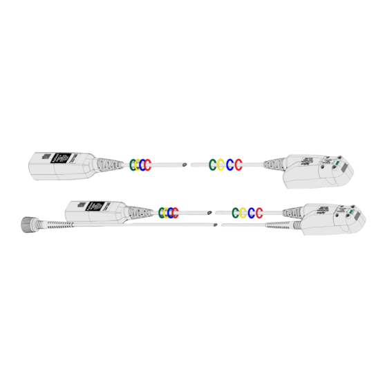
General Information Accessories Accessories Supplied Accessories The N2820A and N2821A probes come with the accessories shown Figure 2. To learn how to use these accessories, refer to Chapter 2, “Making Measurements”. Figure 2 Supplied Accessories N2820/1A User’s Guide... - Page 11 100 m Head SENSE N2825A User-defined R Head SENSE N2826A Replacement unsocketed sensor leads (22 AWG) N2827A Secondary Cable for use with N2820A probe N2828A Replacement MBB Headers N2829A Replacement MBB Receptacles and socketed sensor leads (22 AWG) N2820/1A User’s Guide...
-
Page 12: Inspecting The Probe
Keysight Technologies Sales Office. If the shipping container is damaged, or the cushioning materials show signs of stress, notify the carrier as well as your Keysight Technologies Sales Office. Keep the shipping materials for the carrier’s inspection. The Keysight Technologies office will arrange for repair or replacement at Keysight Technologies’... -
Page 13: Returning The Probe For Service
Perform the following steps before shipping the probe back to Keysight Technologies for service. Contact your nearest Keysight sales office for information on obtaining an RMA number and return address. Write the following information on a tag and attach it to the malfunctioning equipment. - Page 14 General Information Returning the Probe for Service Before returning an instrument for service, you must first call the Call Center at 1 (800) 829-4444. N2820/1A User’s Guide...
-
Page 15: Safety Information
General Information Safety Information Safety Information This manual provides information and warnings essential for operating this probe in a safe manner and for maintaining it in safe operating condition. Before using this equipment and to ensure safe operation and to obtain maximum performance from the probe, carefully read and observe the following warnings, cautions, and notes. - Page 16 General Information Safety Information Observe Probe Ratings. WARNING Do not apply any electrical potential to the probe input which exceeds the maximum rating of the probe. Make sure to comply with the voltage versus frequency derating curve found in this manual. Keep Away From Live Circuits.
- Page 17 General Information Safety Information Do not use the probe or oscilloscope in a manner not specified by the WARNING manufacturer. Service instructions are for trained service personnel. To avoid WARNING dangerous electric shock, do not perform any service unless qualified to do so.
- Page 18 General Information Safety Information Before turning on the instrument, you must connect the protective earth WARNING terminal of the instrument to the protective conductor of the (mains) power cord. The mains plug shall only be inserted in a socket outlet provided with a protective earth contact.
- Page 19 Keysight N2820/1A High-Sensitivity Current Probes User’s Guide 2 Making Measurements Introduction / 20 Quick Start / 23 Step 1. Attach the Sensor Leads / 23 Step 2. Attach the Probe Head / 24 Step 3. Attach the Secondary Cable / 25 Step 4.
-
Page 20: Making Measurements Introduction
Making Measurements Introduction Introduction The probes are supplied with three interchangeable R probe SENSE heads: N2822A, N2824A, and N2825A. To begin using the probe, refer to “Quick Start” on page 23. Figure 3 on page 21 illustrates the relative merits of using the three different heads with the different sensor leads. - Page 21 Making Measurements Introduction Figure 3 Different Probing Connections With Relative Merit N2820/1A User’s Guide...
- Page 22 Making Measurements Introduction Sensor Leads The probe heads do not come with the sensor leads soldered on them. Instead, you must solder on the appropriate leads as described in “Quick Start” on page 23. Always wear an ESD wrist strap when working with active probes. Not CAUTION doing so can result in the probe becoming permanently damaged.
-
Page 23: Quick Start
Making Measurements Quick Start Quick Start Step 1. The probe heads do not come with the leads soldered on them. Attach the Sensor Leads Instead, you must solder on one of the following types of sensor leads to the probe head. •... - Page 24 Making Measurements Quick Start Figure 5 Lead Positions on PC Board Step 2. Gently press the head into position on the probe amplifier while Attach the Probe Head carefully mating the connector as shown in Figure Figure 6 Attaching and Removing a Head from the Probe Never apply excessive force when attaching the head.
- Page 25 If lead wires are attached, do not pull on the wires as this could damage CAUTION the head. Step 3. This step is for N2820A two-channel probes only. N2821A probes Attach the Secondary are not designed for use with the secondary cable and cannot be Cable upgraded.
- Page 26 Step 4. Connect Probe to Scope Connect the probe to any available oscilloscope channel. For N2820A probes always connect the primary cable first promptly NOTE followed by the secondary cable. This enables the oscilloscope to automatically associate the two inputs to the same probe.
- Page 27 NOTE to adjacent channels may reduce clutter, this is not a requirement. For example, you could connect an N2820A’s primary cable to channel 2 and its secondary cable to channel 4. To ensure the display of accurate waveforms, always connect the NOTE supplied ground lead when probing battery-powered devices.
- Page 28 Quick Start Figure 9 Probe Configuration Dialog Box (N2821A Probe) Click the tab that represents the probe. In the case of N2820A probes, the probe’s primary channel. If you are using an N2821A probe, use the Primary Channel Output field to configure the input channel as a zoomed-in or zoomed-out channel.
- Page 29 Configuring the Probe on InfiniiVision Oscilloscopes Press the front-panel channel key that is associated with the probe. In the case of N2820A probes, the probe’s primary channel. Press the Probe softkey. If you are using an N2821A probe, press the Zoom-In softkey to toggle between zoomed-in (blue selection box on softkey) or zoomed-out (clear selection box) for the channel.
- Page 30 Making Measurements Quick Start Figure 10 R-Sense Entry Box N2820/1A User’s Guide...
-
Page 31: To Measure Battery-Powered Devices
Making Measurements To Measure Battery-Powered Devices To Measure Battery-Powered Devices When making measurements on a battery-powered (floating) device, such as a mobile phone, always connect the supplied ground lead between ground on your device and the probe’s ground connector as shown in Figure 11. -
Page 32: To Measure Charge On An Infiniium Oscilloscope
A new measurement, Charge, is available on Infiniium oscilloscopes. This measurement determines the total current consumption over time with the results listed in Ampere-hours (Ah). For N2820A probes, the measurement includes the area under the curve across both zoomed-in and zoomed-out waveforms. - Page 33 Making Measurements To Measure Charge on an Infiniium Oscilloscope To make a Charge measurement Connect the probe. If an N2825A user-defined head is used, enter the R resistance as explained in “Step 5. Configuring the Probe SENSE on Infiniium Oscilloscopes” on page 27.
-
Page 34: To Measure Charge On An Infiniivision Oscilloscope
A new measurement, Charge, is available on InfiniiVision oscilloscopes. This measurement determines the total current consumption over time with the results listed in Ampere-hours (Ah). For N2820A probes, the measurement includes the area under the curve across both zoomed-in and zoomed-out waveforms. Figure 14 shows a Charge measurement. - Page 35 Making Measurements To Measure Charge on an InfiniiVision Oscilloscope To make a Charge measurement Connect the probe. If an N2825A user-defined head is used, enter the R resistance as explained in “Step 6. Configuring the Probe SENSE on InfiniiVision Oscilloscopes” on page 29.
-
Page 36: To Simultaneously View Zoomed-In/Zoomed-Out Waveforms
Making Measurements To Simultaneously View Zoomed-In/Zoomed-Out Waveforms To Simultaneously View Zoomed-In/Zoomed-Out Waveforms When using an N2820A probe, zoomed-in and zoomed-out waveforms can be simultaneously viewed on: • 9000 H-Series Infiniium oscilloscopes, and • 9000A Series Infiniium oscilloscopes In dual-grid view (shown in... - Page 37 Making Measurements To Simultaneously View Zoomed-In/Zoomed-Out Waveforms Figure 15 Displayed Zoom Windows On the display, the bounding-area box identifies the portion of the zoomed-out waveform that is displayed in the zoomed-in window. Oscilloscope’s Zoom Mode This is shown in Figure 15.
- Page 38 Making Measurements To Simultaneously View Zoomed-In/Zoomed-Out Waveforms For best measurement results, click Setup > Acquisition and select one NOTE of the High Resolution settings. N2820/1A User’s Guide...
-
Page 39: To Make Measurements Without Interrupting Your Dut
Making Measurements To Make Measurements Without Interrupting Your DUT To Make Measurements Without Interrupting Your DUT The supplied Make-Before-Break (MBB) connectors allow you to easily connect and disconnect your probe without interrupting the Device-Under-Test (DUT). With the MBB connector you can quickly probe multiple locations on your DUT without having to solder or unsolder the leads. - Page 40 Making Measurements To Make Measurements Without Interrupting Your DUT Figure 17 Socketed Lead Snaps Onto the MBB Receptacle To Use the MBB Connector Solder one or more headers onto your DUT. Snap the sensor lead’s socket onto the receptacle. Once attached to the receptacle, the socket cannot easily be removed NOTE without deforming the receptacle.
- Page 41 Making Measurements To Make Measurements Without Interrupting Your DUT Figure 18 illustrates how the MBB connection changes as you gently push the receptacle onto the header while using an N2822/4A head. Figure 19 on page 43 shows the schematic when using the MBB with an N2825A user-defined head.
- Page 42 Making Measurements To Make Measurements Without Interrupting Your DUT Figure 18 Connecting the MBB Connector with N2822/4A Head N2820/1A User’s Guide...
- Page 43 Figure 19 MBB Connector With N2825A User-Defined Head To Download the Header You can download a Gerber file from Keysight that defines many of Gerber File the parameters needed to design the PC board connection for the MBB header. Gerber files can be imported into many PC board layout applications.
-
Page 44: To Determine Maximum Input Voltage And Current
Making Measurements To Determine Maximum Input Voltage and Current To Determine Maximum Input Voltage and Current The probe’s maximum input voltage and current values are derived using the equations in this section. Exceeding these values may result in the signal being clipped on the screen. To perform the calculations, you need the probe’s maximum output voltage (linear operation) and the Gain, which are documented in Chapter... - Page 45 Making Measurements To Determine Maximum Input Voltage and Current For example, when using an N2824A probe head with a zoom-in signal, the maximum input current would be 400 mA. N2820/1A User’s Guide...
-
Page 46: Extreme Temperature Probing
Making Measurements Extreme Temperature Probing Extreme Temperature Probing By constructing your own long sensor leads, you can use the N2820/1A probes for extreme temperature probing, such as monitoring a product in an environmental chamber. The following two sensor lead examples provide accurate measurements: •... -
Page 47: Burden Voltage Of N2822/4A Probe Heads
Making Measurements Burden Voltage of N2822/4A Probe Heads Burden Voltage of N2822/4A Probe Heads When an N2822/4A head is used, the resistance of the head’s connectors, sensor leads, and internal R resistor is connected SENSE in series with the DUT’s circuit and current is flowing through the probe head, as shown in Figure ×... - Page 48 Making Measurements Burden Voltage of N2822/4A Probe Heads Table 4 Resistance Added by Head Components Component Resistance Contribution (Round Trip) Sensor Leads Without Socket 20 mΩ Sensor Leads With Socket 40 mΩ MBB Header Only (Not Connected) 20 mΩ MBB Header/Receptacle/Socket 40 mΩ...
-
Page 49: Dynamic Range
36. Figure 21 Small Pulses in the Presence of Large Pulses Value and Dynamic Since the N2820A probe has two outputs, each with a different SENSE Range gain, dynamic range encompasses both channels while using a single R value. - Page 50 Making Measurements Dynamic Range 2.2A 93dB ------------- - 50 μA The value of the R resistor can range from 1 mΩ to 1 MΩ as SENSE shown in Figure 35, “Current Range of N2822/4A Heads,” on page 78. Using these two R values in different measurements, SENSE the dynamic range could be increased to 100 dB.
-
Page 51: Using N2825A Probe Heads
Keysight N2820/1A High-Sensitivity Current Probes User’s Guide 3 Using N2825A Probe Heads To Manually Identify the R Resistance / 52 SENSE On Infiniium Oscilloscopes / 52 On InfiniiVision Oscilloscopes / 53 To Identify the R Resistance Using a Unique Name / 54... -
Page 52: Sense Resistance Using A Unique Name
Click the Setup > Probe Configuration menu command to view the Probe Configuration dialog box, shown in Figure Figure 22 Infiniium Dialog Box With N2825A Heads Click the tab that represents the probe. In the case of N2820A probes, the probe’s primary channel. N2820/1A User’s Guide... - Page 53 29 and is repeated here. Press the front-panel channel key that is associated with the probe. In the case of N2820A probes, the probe’s primary channel. Click the Probe softkey followed by the R-Sense softkey. Enter the resistance of the R resistor that you are using.
-
Page 54: Sense Resistance Using An Id Resistor
Using N2825A Probe Heads To Identify the R Resistance Using a Unique Name SENSE To Identify the R Resistance Using a Unique Name SENSE This procedure is for Infiniium oscilloscopes, only. InfiniiVision NOTE oscilloscopes do not support the assigning of names to identify N2825A/R combinations. - Page 55 SENSE N2825A head. You can order additional N2825A heads from Keysight. In the following procedure, always wear an ESD wrist strap and work at a CAUTION static-safe workstation. Not doing so can result in the probe head becoming permanently damaged.
- Page 56 Using N2825A Probe Heads To Identify the R Resistance Using an ID Resistor SENSE Remove the probe head by gently pulling the head straight off the probe in the direction shown. Figure 23 Removing the Probe Head Remove the four hex screws that secure the cover of the N2825A head and remove the cover.
- Page 57 Using N2825A Probe Heads To Identify the R Resistance Using an ID Resistor SENSE Figure 25 Remove PC Board On the reverse side of the PC board, locate ID resistor, R2, as shown in Figure Figure 26 Location of ID Resistor (R2) Replace the ID resistor with any of the values listed in Table 7.
- Page 58 61.9 kΩ Resistor, ±1%, 0.063W, TC±100 thick film 0402 SMT Replace the N2825A’s cover using the four screws. (M1.6 x 0.35, 5 mm long, Keysight part number 0515-5210) To avoid damaging the aluminum casting, do not over tighten the screws. CAUTION Connect the N2825A to an N2820/1A probe and connect the probe to the oscilloscope.
- Page 59 Using N2825A Probe Heads To Identify the R Resistance Using an ID Resistor SENSE On InfiniiVision oscilloscopes, a Press the front-panel channel key that is associated with the probe’s primary input. b Click the Probe softkey. c Press the R-Sense softkey and enter the resistance of the R SENSE resistor that you are using.
- Page 60 Using N2825A Probe Heads To Identify the R Resistance Using an ID Resistor SENSE Table 7 N2825A Identification N2825A Associated DUT R ID Resistor Probe Name Registered SENSE Marking Resistor Value Value on the Oscilloscope N2820/1A User’s Guide...
-
Page 61: To Add A Custom Internal Rsense
Using N2825A Probe Heads To Add a Custom Internal R Resistor SENSE To Add a Custom Internal R Resistor SENSE If you need to use a different R resistance than provided by the SENSE N2822A and N2824A heads, you can convert an N2825A head to an internal R head. - Page 62 Using N2825A Probe Heads To Add a Custom Internal R Resistor SENSE Figure 27 Removing the Probe Head Remove the four hex screws that secure the head’s cover and remove the cover. Figure 28 Removing the Cover Change or add the R resistor (R1) as shown in Figure SENSE...
- Page 63 Resistor (R1) SENSE Replace the head’s cover using the four screws. (M1.6 x 0.35, 5 mm long, Keysight part number 0515-5210) To avoid damaging the aluminum casting, do not over tighten the screws. CAUTION Connect the N2825A to an N2820/1A probe and connect the probe to the oscilloscope.
- Page 64 Using N2825A Probe Heads To Add a Custom Internal R Resistor SENSE On InfiniiVision oscilloscopes, a Press the front-panel channel key that is associated with the probe’s primary input. b Click the Probe softkey. c Press the R-Sense softkey and enter the resistance of the R SENSE resistor that you are using.
-
Page 65: Probe Calibration
Keysight N2820/1A High-Sensitivity Current Probes User’s Guide 4 Probe Calibration This chapter provides procedures for calibrating the probe on an Infiniium oscilloscope and on an InfiniiVision Oscilloscope. “To Calibrate the Probe on Infiniium Oscilloscopes” on page 66 “To Calibrate the Probe on InfiniiVision Oscilloscopes”... -
Page 66: To Calibrate The Probe On Infiniium Oscilloscopes
Probe Calibration To Calibrate the Probe on Infiniium Oscilloscopes To Calibrate the Probe on Infiniium Oscilloscopes During this calibration, you may be prompted to make one or more adjustments. These adjustments, located on the underside of the probe amplifier, are shown in Figure 32 on page 69. - Page 67 Oscilloscope’s rear-panel (as shown in Figure 30). • On N2820A probes, do not connect the secondary cable at this time. • Connect both the N2825A’s sensor leads (red and black wires) to the black test clip of the Pomona 3788 as shown in...
- Page 68 Probe Calibration To Calibrate the Probe on Infiniium Oscilloscopes Let the probe warm up for 15 minutes. On the oscilloscope, click Setup > Channel to open the Channel Setup dialog box and select the channel tab for the connected probe. Click Probes…...
- Page 69 Probe Calibration To Calibrate the Probe on Infiniium Oscilloscopes The screwdriver provided with the probe is the preferred adjustment tool. NOTE Figure 32 Location of Calibration Adjustments N2820/1A User’s Guide...
-
Page 70: To Calibrate The Probe On Infiniivision Oscilloscopes
1. Connect the probe to the oscilloscope a Turn the oscilloscope on. b Plug the primary channel of the N2820A probe into the oscilloscope channel you are intending to use. c If applicable, plug the secondary channel of the probe into the oscilloscope channel you are intending to use. - Page 71 Probe Calibration To Calibrate the Probe on InfiniiVision Oscilloscopes Allow the oscilloscope and probe to warm up for at least NOTE 20 minutes before performing the probe calibration. 2. Manually adjust the probe’s initial offset Calibration fails if the probe has too much initial offset. The probe’s offset can be zeroed manually using the following procedure.
- Page 72 Probe Calibration To Calibrate the Probe on InfiniiVision Oscilloscopes ii) Turn on Averaging with 16 averages. iii) For both channels, set the V/div as small as possible to fit the waveform on screen. For the zoomed-in channel, this should be less than 10μA.
- Page 73 Probe Calibration To Calibrate the Probe on InfiniiVision Oscilloscopes 3. Initiate Calibration a In the Channel menu, press the Probe softkey. When you connect the probe, the Calibrate Probe softkey in the Channel NOTE Probe menu becomes active. b Press the Calibrate Probe softkey and then press the OK softkey to begin calibration.
- Page 74 Probe Calibration To Calibrate the Probe on InfiniiVision Oscilloscopes N2820/1A User’s Guide...
-
Page 75: Characteristics And Specifications
Zoomed-In Input Current Range Versus Supply Voltage / 81 Dimensions / 83 This chapter provides the characteristics and specifications for the N2820A and N2821A probes. The probe should be warmed up for at least 20 minutes before any testing and the environmental conditions should not exceed the probe’s specified limits. -
Page 76: 5 Characteristics And Specifications
Maximum Output Voltage (Linear Operation) Burden Voltage (voltage drop on R Measured current * R SENSE SENSE Dynamic Range 20,000:1, 86 dB (N2820A) 1,000:1, 60 dB (N2821A) Oscilloscope Input Impedance 1 MΩ Input Impedance 1.5 GΩ single ended 3.0 GΩ differential... - Page 77 Characteristics and Specifications Table 11 Environmental Characteristics Item Characteristic Temperature (operating) Operating: 0° C to 40° C Non-Operating: –40° C to 70° C Humidity (operating) Operating: tested at 95% RH @ +40° C Non-Operating: tested at 90% RH, +65° C 8 kV HBM Indoor Use This probe is rated for indoor use only...
-
Page 78: Current Range Graphs
Characteristics and Specifications Current Range Graphs Current Range Graphs The following graphs show the minimum and maximum current ranges versus R resistance. SENSE These graphs represent a condition where the sensor leads are solder NOTE attached to the R resistor, the maximum probe-head power rating SENSE of 500 mW is observed, and the oscilloscope is set to high-resolution. - Page 79 Characteristics and Specifications Current Range Graphs Figure 36 Current Range of N2825A User-Defined Head N2820/1A User’s Guide...
-
Page 80: Zoomed-In Input Voltage Range Versus Supply Voltage
Characteristics and Specifications Zoomed-In Input Voltage Range Versus Supply Voltage Zoomed-In Input Voltage Range Versus Supply Voltage For the zoomed-in probe input, the following graph shows the typical input voltage range allowed based on the supply voltage that you are measuring. For example, when measuring a 5V input, the input voltage range is ∴45 mV. -
Page 81: Zoomed-In Input Current Range Versus Supply Voltage
Characteristics and Specifications Zoomed-In Input Current Range Versus Supply Voltage Zoomed-In Input Current Range Versus Supply Voltage For the zoomed-in probe input, the following two graphs show the typical input current range allowed based on the supply voltage that you are measuring. For example, when using an N2824A head and measuring a 5V input, the current range is ∴0.54A. - Page 82 Characteristics and Specifications Zoomed-In Input Current Range Versus Supply Voltage Figure 39 Zoomed-In Input Current Range Versus Supply Voltage (N2822A 20 mΩ Head) N2820/1A User’s Guide...
-
Page 83: Dimensions
Characteristics and Specifications Dimensions Dimensions Figure 40 Probe and Tip Dimensions N2820/1A User’s Guide... - Page 84 Characteristics and Specifications Dimensions N2820/1A User’s Guide...
-
Page 85: Performance Data Plots
N2820A Frequency Response / 86 N2820A Common Mode Rejection Ratio / 88 N2820A Step Response / 89 N2820A Step Tracking / 90 N2820A Input Impedance / 92 Input Load Model / 93 This chapter provides the performance plots for the N2820A. -
Page 86: N2820A Frequency Response
Performance Data Plots N2820A Frequency Response N2820A Frequency Response BW: ........... 590 kHz... - Page 87 Performance Data Plots N2820A Frequency Response BW: ........... 3.5 MHz...
-
Page 88: N2820A Common Mode Rejection Ratio
Performance Data Plots N2820A Common Mode Rejection Ratio N2820A Common Mode Rejection Ratio Figure 43 Common Mode Rejection Ratio (CMRR) N2820/1A User’s Guide... -
Page 89: N2820A Step Response
Performance Data Plots N2820A Step Response N2820A Step Response Zoomed-In Channel 10–90% rising edge step: ..... . 584.2 ns 20–80% rising edge step: ..... . 365.8 ns Zoomed-Out Channel 10–90% rising edge step: . -
Page 90: N2820A Step Tracking
Performance Data Plots N2820A Step Tracking N2820A Step Tracking Input Step 10–90% Rise Time: ......1.688 µs 20–80% Rise Time: . - Page 91 Performance Data Plots N2820A Step Tracking Input Step 10–90% Rise Time: ......446.9 ns 20–80% Rise Time: .
-
Page 92: N2820A Input Impedance
Performance Data Plots N2820A Input Impedance N2820A Input Impedance Figure 47 Input Impedance N2820/1A User’s Guide... -
Page 93: Input Load Model
Performance Data Plots Input Load Model Input Load Model Single Ended: ......... 1.5 G Ω... - Page 94 Performance Data Plots Input Load Model N2820/1A User’s Guide...
-
Page 95: Performance Verification
Average Gain of Zoomed-Out Channel / 101 Performance Test Record / 105 This chapter describes how to verify the performance of the N2820A and N2821A probes. The performance verification requires an N2825A probe head and consists of verifying the probe’s DC gain. -
Page 96: 7 Performance Verification
Digital Multimeter General purpose instrument for DC voltage measurement. DC Power Supply Recommended: ±20V Maximum: ≤ ±35V Probe Power Supply Keysight 1143A Probe Offset Control and Power Module Probe Adapter Keysight N1022A/B Probe Adapter. Adapters 3.5 mm-to-BNC BNC-to-banana N2820/1A User’s Guide... -
Page 97: Average Gain Of Zoomed-In Channel
Performance Verification Average Gain of Zoomed-In Channel Average Gain of Zoomed-In Channel This procedure applies to both N2820A and N2821A probes. Allow the probe to warm up for at least 20 minutes. NOTE Snap an N2825A head onto the N2820/1A probe and connect the... - Page 98 Performance Verification Average Gain of Zoomed-In Channel Record the value of +V measured on the multimeter: ________________ Move the multimeter’s leads to the banana plug on the output of the N1022A/B as shown in Figure Record the value of +V measured on the multimeter: :________________ Figure 50...
- Page 99 Performance Verification Average Gain of Zoomed-In Channel positive gain ----------- - positive gain: ________________ Set the DC power supply to –20 mV. Although this is the recommended setting, you can use any negative NOTE voltage less than –35 mV. Connect the multimeter on the DC power supply as shown in Figure 49 on page 97.
- Page 100 Performance Verification Average Gain of Zoomed-In Channel positive gain negative gain average gain --------------------------------------------------------------- average gain (zoomed-in):________________ The average gain (zoomed-in) should be 300 ±3%. Enter the value Table 14 on page 105. N2820/1A User’s Guide...
-
Page 101: Average Gain Of Zoomed-Out Channel
Performance Verification Average Gain of Zoomed-Out Channel Average Gain of Zoomed-Out Channel Perform this procedure only for N2820A probes. Allow the probe to warm up for at least 20 minutes. NOTE Snap an N2825A head onto the N2820/1A probe and connect the... - Page 102 Performance Verification Average Gain of Zoomed-Out Channel Record the value of +V measured on the multimeter: :________________ Move the multimeter’s leads to the banana plug on the output of the N1022A/B as shown in Figure Record the value of +V measured on the multimeter: :________________ Figure 52...
- Page 103 Performance Verification Average Gain of Zoomed-Out Channel positive gain ----------- - positive gain:________________ Set the DC power supply to –500 mV. Although this is the recommended setting, you can use any negative NOTE voltage less than –700 mV. Connect the multimeter on the DC power supply as shown in Figure 51 on page 101.
- Page 104 Performance Verification Average Gain of Zoomed-Out Channel positive gain negative gain average gain --------------------------------------------------------------- average gain (zoomed-out):________________ The average gain (zoomed-out) should be 1.97 ±3%. Enter the value gain in Table 14 on page 105. N2820/1A User’s Guide...
-
Page 105: Performance Test Record
Recommended next test date: Recommended Test Interval: 1 year / 2000 hours Probe Amplifier Test Limits Result Pass/Fail Average Gain of Zoomed-In Channel (N2820/1A) Average Gain (zoomed-in) 300±3% Average Gain of Zoomed-Out Channel (N2820A only) Average Gain (zoomed-out) 1.97±3% N2820/1A User’s Guide... - Page 106 Performance Verification Performance Test Record N2820/1A User’s Guide...
- Page 107 27, 52, current range, 78, make-before-break connector, connecting, maximum power dissipation, inspecting, MBB connector, leads, 22, MBB header, N2820A connection order, dimensions, Gerber file, service, dual-grid view, 8, MBB receptacle, probe calibration, dynamic range Meas key, Probe Configuration dialog box, 27, 52,...
- Page 108 Index probe head ID resistor, Zoom Mode, N2822/4A, zoom windows, N2825A, turning off, probe power supply, zoom-in, Probe softkey, 29, 53, Zoom-In softkey, probing connections, choices, zoom-out, receptacle, replacement kits, returning for service, RSENSE resistors, R-Sense softkey, 29, 53, safety, Safety Considerations, safety warnings, secondary cable, 11,...
- Page 109 N2820/1A User’s Guide...
- Page 110 This information is subject to change without notice. © Keysight Technologies 2018 March 2018 *N2820-97006* www.keysight.com...
Need help?
Do you have a question about the N2820A and is the answer not in the manual?
Questions and answers