Table of Contents
Advertisement
Quick Links
Advertisement
Table of Contents

Related Manuals for Keysight N2780B


Summary of Contents for Keysight N2780B
- Page 1 Keysight N2780/1/2/3B Current Probes User’s Guide...
- Page 2 WARNING notice until the herein. Should Keysight and the user have a cial computer software documentation. No indicated conditions are fully separate written agreement with warranty additional government requirements beyond understood and met.
-
Page 3: Table Of Contents
Specifications and Characteristics Performance Verification Returning the Probe for Service The N2780B series current probes are high bandwidth, active current probes, featuring flat bandwidth, low noise (2.5 mA ) and low circuit insertion loss. In conjunction with the companion N2779A power supply, this probe can be used with any oscilloscope having a high-impedance BNC input. - Page 4 Sales Office. If the shipping container is damaged, or the cushioning materials show signs of stress, notify the carrier as well as your Keysight Technologies Sales Office. Keep the shipping materials for the carrier’s inspection. The Keysight Technologies office will arrange for repair or replacement at Keysight Technologies’ option without waiting for claim settlement.
-
Page 5: N2780/1B Current Probes
N2780/1B Current Probes N2780/1B Current Probes The following figure identifies the components of the N2780/1B probes. Figure 1 N2780/1B Probe Parts Identification Sensor Head Clamps the conductor being measured, and carries out the actual current measurement. It is a precision assembly including a molded component, a ferrite core, and a Hall effect element. - Page 6 N2780/1B Current Probes Current Direction Indication Align the sensor so that the current direction indication corresponds to the direction of current flow through the conductor to be measured. Opening Lever Opens the clamp. Always use it to open and close the clamp. LOCK/UNLOCK Indication ...
- Page 7 N2780/1B Current Probes Zero Adjustment Dial (ZERO ADJ) Use the zero adjustment dial to correct for the effect of a voltage offset or temperature drift on the device. When beginning a measurement, after demagnetizing, always carry out a zero adjustment. N2780/1/2/3B User’s Guide...
-
Page 8: N2782/3B Current Probes
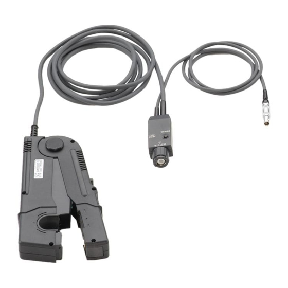
N2782/3B Current Probes N2782/3B Current Probes The following figure identifies the components of the N2782/3B probes. Figure 2 N2782/3B Probe Parts Identification Coarse Adjustment Trimmer This adjustment should only be carried out if the probe offset is outside the range of the zero adjustment dial. - Page 9 (30A/50 Ω MHz: N2782B-FG), 7 (150A/10 MHz: N2781B-FG), 41 (500A/2 MHz: Ω Ω N2780B-FG), 25 (30A/100MHz: N2783B-FG). Ω Power Supply Cable Connect this to the N2779A power supply receptacle to supply power to the sensor terminator. Zero Adjustment Dial (ZERO ADJ) ...
-
Page 10: Making Measurements
Ω Ω measurements. If the oscilloscope input impedance cannot be set to then the Keysight E2697A impedance adapter can be purchased. Ω 4 With the oscilloscope input at ground, adjust the trace to the zero position. 5 Set the oscilloscope’s input coupling to DC. - Page 11 Making Measurements Figure 3 Connecting the Probe to the Oscilloscope CAUTION When disconnecting the output connector, be sure to release the lock, then pull the connector. Forcibly pulling the connector without releasing the lock, or pulling on the cable will result in damage to the terminator. CAUTION Do not demagnetize while the conductor being measured is clamped.
- Page 12 Making Measurements 9 Press the probe’s demagnetizing switch (DEMAG). 10 Turn the probe’s zero adjustment dial to adjust the trace to the zero position. N2782/3B probes have a coarse adjustment trimmer. If zero adjustment NOTE is not possible on an N2782/3B probe, turn the coarse adjustment trimmer to bring the trace within the range of adjustment by the zero adjustment dial.
-
Page 13: Safe Probing
Safe Probing Safe Probing This device is designed to comply with IEC 61010 Safety Standards, and has been thoroughly tested for safety prior to shipment. However, mishandling during use could result in injury or death, as well as damage to the device. Be certain that you understand the instructions and precautions in the manual before use. - Page 14 Before using the device the first time, verify that it operates normally to ensure that the no damage occurred during storage or shipping. If you find any damage, contact your dealer or Keysight representative. CAUTION This device is not designed to be entirely water- or dust- proof. To avoid damage, do not use it in a wet or dusty environment.
- Page 15 Safe Probing CAUTION The sensor head is a precision assembly including a molded component, a ferrite core, and a Hall effect element. It may be damaged if subjected to sudden changes in ambient temperature, or mechanical strain or shock, and therefore great care should be exercised in handling it. CAUTION The matching surfaces of the sensor head are precision ground, and should be treated with care.
- Page 16 Safe Probing CAUTION Do not place any un-clamped conductor with an electric current of a frequency of 10 kHz or more near the sensor head. Current flowing in the conductor nearby may heat up the sensor head and cause its temperature to rise, leading to damage to the sensor.
- Page 17 Safe Probing CAUTION The device may sustain damage from self-heating even at current levels that are lower than the maximum current value defined by the maximum rated current. The maximum rated current is a recommended value that assumes sine wave input under standard conditions. Self-heating may increase if the ambient temperature increases or the measurement current waveform contains other frequency components.
- Page 18 The output of this unit is terminated internally. Use an oscilloscope with NOTE an input impedance of at least 1 M or use the Keysight E2697A Ω impedance adapter. Immediately after powering on the probe, the probe may be subject to an NOTE appreciable offset drift due to the effect of selfheating.
- Page 19 Safe Probing Under certain circumstances, oscillation may occur if the probe is NOTE connected to the N2779A power supply while the power supply is on. This does not indicate a malfunction. Oscillation can be stopped and operation restored to normal by opening and closing the sensor head. Depending on the amplitude and frequency of the current being NOTE measured, the sensor head may emit a resonant sound.
- Page 20 Safe Probing At high frequencies, common mode noise may affect measurements NOTE taken on the high voltage side of circuits. If this occurs, reduce the frequency range of the waveform measuring instrument or clamp onto the lowvoltage side of the circuit, as appropriate. See Figure 7 page 20.
-
Page 21: Safety Information
Failure to comply with these precautions or with specific warnings or operating instructions in the product manuals violates safety standards of design, manufacture, and intended use of the instrument. Keysight Technologies assumes no liability for the customer's failure to comply with these requirements. - Page 22 Do Not Modify the Instrument Do not install substitute parts or perform any unauthorized modification to the product. Return the product to an Keysight Sales and Service Office for service and repair to ensure that safety features are maintained. In Case of Damage...
- Page 23 Safety Information Safety Symbols Table 1 Description of Safety related symbols that may appear on a product (Sheet 1 of 2) Symbol Description Direct current Alternating current Both direct and alternating current Three phase alternatingcurrent Earth ground terminal Protective earth ground terminal Frame or chassis ground terminal Terminal is at earth potential Equipotentiality...
- Page 24 Safety Information Table 1 Description of Safety related symbols that may appear on a product (Sheet 2 of 2) Symbol Description Caution, refer to accompanying documentation Caution, risk of electric shock Indicates that only insulated conductors suited to the voltage of the circuit under test can be measured. Application around and removal from HAZARDOUS LIVE conductors is permitted.
-
Page 25: Informations Relatives À La Sécurité
à la conception, à la fabrication et à l’usage normal de l’instrument. Keysight Technologies ne saurait être tenu responsable du non-respect de ces consignes. Les manuels des produits sont fournis avec votre instrument sur CD-ROM et/ou en version papier. - Page 26 à l'appareil. Pour toute opération de maintenance ou de réparation, renvoyez l'appareil à un bureau de vente et de service après-vente Keysight, afin d'être certain que les fonctions de sécurité seront maintenues. En cas de dommages Les instruments endommagés ou défectueux doivent être désactivés et protégés contre toute utilisation involontaire jusqu'à...
- Page 27 Safety Information Symboles de sécurité: Table 2 Description des Symboles de Sécurité qui pourraient apparaître sur le produit. (Sheet 1 of 2) Symboles Description Courant continu. Courant alternatif. Courant continu et alternatif. Courant alternative triphasé. Borne de terre (masse). Borne de terre de protection. Borne de terre reliée au cadre ou au châssis.
- Page 28 Safety Information Table 2 Description des Symboles de Sécurité qui pourraient apparaître sur le produit. (Sheet 2 of 2) Symboles Description Attention. Consultez la documentation fournie. Attention, danger d'électrocution. Ne pas appliquer ou enlever sur des conducteurs SOUS TENSION DANGEREUSE Application ou retrait autorisés sur les conducteurs SOUS TENSION DANGEREUSE Attention, surface chaude Rayonnement ionisant...
-
Page 29: Specifications And Characteristics
Specifications and Characteristics Specifications and Characteristics Table 3 lists specifications are guaranteed. Table 4 lists the characteristics, which are non-warranted. Table 3 Specifications (Warranted) N2780B N2781B N2782B N2783B Amplitude accuracy ±1.0% of reading ±1.0% of reading ±1.0% of reading ±1.0% of reading (DC or 45 to 66 Hz, ±500 mA at 23... - Page 30 Specifications and Characteristics Table 4 Characteristics (Non-Warranted) (Sheet 2 of 2) N2780B N2781B N2782B N2783B Temperature coefficient for sensitivity (within a ± 2% or less range of 0 C to 40 C or F to 104 Effect of external Equivalent to a...
- Page 31 Specifications and Characteristics Table 5 General Characteristics N2780B N2781B N2782B N2783B Diameter of measurable 20 mm (0.79”) 5 mm (0.2”) conductors Cable Lengths (Approximate) Sensor 2m (78.7”) 1.5m (59”) Power supply 1m (39.4”) 1m (39.4”) External Sensor Dimensions (Approximate) Width 176 mm (6.93”)
- Page 32 Specifications and Characteristics Table 6 Environmental Specifications (Sheet 2 of 2) Item Specification Pollution degree Pollution degree 2 For indoor use only Measurable conductors Insulated conductor N2780B Plots Frequency [Hz] Figure 8 Frequency Response Characteristic N2780B N2780/1/2/3B User’s Guide...
- Page 33 Specifications and Characteristics Frequency [Hz] Figure 9 Derating According to Frequency N2780B (Continuous Maximum Input) Frequency [Hz] Figure 10 Insertion Impedance N2780B N2780/1/2/3B User’s Guide...
- Page 34 Specifications and Characteristics upper limit lower limit N2780A 1000 DC Current [A] Figure 11 DC Accuracy Characteristic N2780B upper limit lower limit N2780A 1000 AC Current Figure 12 AC Amplitude Accuracy Characteristic N2780B N2780/1/2/3B User’s Guide...
- Page 35 Specifications and Characteristics N2781B Plots Frequency [Hz] Figure 13 Frequency Response Characteristic N2781B Frequency [Hz] Figure 14 Derating According to Frequency N2781B (Continuous Maximum Input) N2780/1/2/3B User’s Guide...
- Page 36 Specifications and Characteristics Frequency [Hz] Figure 15 Insertion Impedance N2781B upper limit lower limit N2781A 1000 DC Current [A] Figure 16 DC Accuracy Characteristic N2781B N2780/1/2/3B User’s Guide...
- Page 37 Specifications and Characteristics upper limit lower limit N2781A 1000 AC Current Figure 17 AC Amplitude Accuracy Characteristic N2781B N2782B Plots Frequency [Hz] Figure 18 Frequency Response Characteristic N2782B N2780/1/2/3B User’s Guide...
- Page 38 Specifications and Characteristics Frequency [Hz] Figure 19 Derating According to Frequency N2782B (Continuous Maximum Input) Frequency [Hz] Figure 20 Insertion Impedance N2782B N2780/1/2/3B User’s Guide...
- Page 39 Specifications and Characteristics upper limit lower limit N2782A 0.001 0.01 DC Current [A] Figure 21 DC Accuracy Characteristic N2782B upper limit lower limit N2782A 0.001 0.01 AC Current Figure 22 AC Amplitude Accuracy Characteristic N2782B N2780/1/2/3B User’s Guide...
- Page 40 Specifications and Characteristics N2783B Plots Frequency [Hz] Figure 23 Frequency Response Characteristic N2783B Frequency [Hz] Figure 24 Derating According to Frequency N2783B (Continuous Maximum Input) N2780/1/2/3B User’s Guide...
- Page 41 Specifications and Characteristics Frequency [Hz] Figure 25 Insertion Impedance N2783B upper limit lower limit N2783A 0.001 0.01 DC Current [A] Figure 26 DC Accuracy Characteristic N2783B N2780/1/2/3B User’s Guide...
- Page 42 Specifications and Characteristics upper limit lower limit N2783A 0.001 0.01 AC Current Figure 27 AC Amplitude Accuracy Characteristic N2783B N2780/1/2/3B User’s Guide...
-
Page 43: Performance Verification
N2780B; ........ - Page 44 Performance Verification Amplitude Accuracy Test 1 Connect the equipment as shown in Figure 28. Warm up all instruments for 30 minutes before starting the test procedure. While the test system is warming up, clean the magnetic contacts on the probe jaw. Figure 28 Test Setup Shown with N2782B 2 Press the DEMAG button on the probe terminator.
- Page 45 Amplitude: N2780B: ........6.5A N2781B: ........3A N2782B: .
-
Page 46: Returning The Probe For Service
Perform the following steps before shipping the probe back to Keysight Technologies for service. 1 Contact your nearest Keysight sales office for information on obtaining an RMA number and return address. 2 Write the following information on a tag and attach it to the malfunctioning equipment. - Page 47 N2779A power supply, 3, coarse adjustment trimmer, and oscillation, current direction indication, 6, 9, N2780/1B probes, un-clamped conductor, avoid, N2780B plots, N2781B plots, N2782B plots, DEMAG N2783B plots, ZERO ADJ (N27802/3B), switch, 6, zero adjustment, 11, DEMAG switch,...
- Page 48 Printed in Malaysia Part Number N2780-97008 *N2780-97008*...
Need help?
Do you have a question about the N2780B and is the answer not in the manual?
Questions and answers