Table of Contents
Advertisement
Advertisement
Table of Contents

Subscribe to Our Youtube Channel
Related Manuals for Keysight N2818


Summary of Contents for Keysight N2818
- Page 1 Keysight N2818/9A Differential Probes User’s Guide...
- Page 2 Notices © Keysight Technologies 2014, 2015, 2016, WARRANTY TERMS IN THE SEPARATE writing elsewhere in the EULA. Keysight shall 2020 AGREEMENT WILL CONTROL. be under no obligation to update, revise or otherwise modify the Software. With respect No part of this manual may be reproduced in...
-
Page 3: Table Of Contents
Extension Leads Micro IC Clips and Pincer Clips DC Blocking Capacitor Probe Offset Adjustment Safety Information Specifications and Characteristics N2818A Performance Plots N2819A Performance Plots N2818A Performance Verification Scope Vertical Accuracy DC Differential Gain Bandwidth Keysight N2818/9A Differential Probes User Guide... - Page 4 Contents N2819A Performance Verification Scope Vertical Accuracy DC Differential Gain Bandwidth Returning the Probe for Service Contacting Keysight Technologies Index Keysight N2818/9A Differential Probes User Guide...
-
Page 5: Introduction
Keysight N2818/9A Differential Probes User Guide Introduction The N2818A and N2819A differential probes provide superior general-purpose differential signal measurements that are required for high-speed power measurements, vehicle bus measurements, and high-speed digital system designs. Before using the probe, refer to on page 21. -
Page 6: Oscilloscope Compatibility
Using the Probe Oscilloscope Compatibility The N2818A and N2819A probes are compatible with the Keysight oscilloscopes shown in Table 2. Up to four probes can be connected to the oscilloscope at the same time. The table also lists the minimum required firmware version for the oscilloscope. -
Page 7: Channel Identification Rings
Sales Office. If the shipping container is damaged, or the cushioning materials show signs of stress, notify the carrier as well as your Keysight Technologies Sales Office. Keep the shipping materials for the carrier’s inspection. The Keysight Technologies office will arrange for repair or replacement at Keysight Technologies’... -
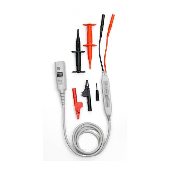
Page 8: Accessories
Alligator Clips (Qty. 2) Offset Adjustment Tool (Qty. 1) Figure 2 N2818A Supplied Accessories Table 3 N2818A Supplied Accessories Accessory Hook Clip (Black) Hook Clip (Red) Alligator Clip (Black) Alligator Clip (Red) Offset Adjustment Tool Keysight N2818/9A Differential Probes User Guide... - Page 9 Extreme Temperature Differential Extension Cables (Black) Extreme Temperature Differential Extension Cables (Red) Extreme Temperature Banana-to-Socketed Tip Adapters for connecting to 0.025” square pins (Black) Extreme Temperature Banana-to-Socketed Tip Adapters for connecting to 0.025” square pins (Red) Keysight N2818/9A Differential Probes User Guide...
-
Page 10: N2819A
N2818A probes. Replacements can be ordered with the N2793-68700 replacement kit. The quantity for each accessory in the kit is the same as listed in the table and originally provided with the probe. Figure 4 N2819A Supplied Accessories Keysight N2818/9A Differential Probes User Guide... - Page 11 Extension Lead, 0.8 mm J-P, 5 cm long (black) Extension Lead, 0.8 mm J-P, 10 cm long (red) Extension Lead, 0.8 mm J-P, 10 cm long (black) Single Signal Pin, 8 mm long DC Blocking Capacitor Variable Pitch Pins Offset Adjustment Tool Keysight N2818/9A Differential Probes User Guide...
-
Page 12: Using The N2818A Probe
This probe is to carry out differential measurements between two points CAUTION on the circuit under test. This probe is not for electrically insulating the circuit under test and the measuring instrument. Figure 5 Inserting the Supplied Clips Keysight N2818/9A Differential Probes User Guide... -
Page 13: Connecting The Extreme Temperature Probing Kit To The Probe
The differential probe, original cables, and original accessories should not be exposed to extreme temperatures. When probing with the extension cables the bandwidth performance will be reduced, see on page 25. Table 6 Keysight N2818/9A Differential Probes User Guide... - Page 14 Connect the red and black extreme temperature hook tip adapters to the extreme temperature differential extension cables which are already connected to the existing probe cables. Figure 7 Connecting the Extreme Temperature Hook Tip Adapters Keysight N2818/9A Differential Probes User Guide...
- Page 15 Connect the red and black extreme temperature banana-to-socketed tip adapters to the extreme temperature differential extension cables which are already connected to the existing probe cables. Figure 8 Connecting the Extreme Temperature Banana-to-Socketed Tip Adapters Keysight N2818/9A Differential Probes User Guide...
-
Page 16: Using The N2819A Probe
Figure 9 Probe Clip, Lead, and Pin Connections To protect against electrical shock, use only the accessories supplied CAUTION with this probe or in the accessory kit. Keysight N2818/9A Differential Probes User Guide... -
Page 17: Single And Variable Pitch Signal Pins
Figure 10 Signal Pins Inserted into the Probe Tip Figure 11 shows the variable pitch pins inserted into the probe tip. Gently rotate the pins to change the distance between the pins. Figure 11 Variable Pitch Pins Inserted into the Probe Tip Keysight N2818/9A Differential Probes User Guide... -
Page 18: Extension Leads
IC clips to extend the grasping jaws. Push the back of the pincer clips to extend their connectors. DC Blocking Capacitor Use the DC blocking capacitor to block out unwanted DC components on the input signal. Figure 13 DC Blocking Capacitor Inserted into the Probe Tip Keysight N2818/9A Differential Probes User Guide... -
Page 19: Probe Offset Adjustment
Set the oscilloscope to Averaging mode (x8 or higher) to reduce oscilloscope noise, if needed. Set the vertical scale of the oscilloscope to 100 mV/div. Using the offset adjustment tool that comes with the probe, adjust the probe offset voltage to zero volts. Keysight N2818/9A Differential Probes User Guide... - Page 20 Using the Probe Figure 14 Location of the Offset Adjustment Keysight N2818/9A Differential Probes User Guide...
-
Page 21: Safety Information
The measurement category of a combination of a PROBE ASSEMBLY and WARNING an accessory is the lower of the measurement categories of the PROBE ASSEMBLY and of the accessory. Keysight N2818/9A Differential Probes User Guide... - Page 22 Disconnect the probe input and the probe ground lead from the circuit under test before disconnecting the probe from the oscilloscope. Keysight N2818/9A Differential Probes User Guide...
- Page 23 The probe cable and the extreme temperature extension cables are CAUTION sensitive parts and, therefore, you should be careful not to damage them through excessive bending or pulling. Avoid any mechanical shocks to this product in order to guarantee accurate performance and protection. Keysight N2818/9A Differential Probes User Guide...
- Page 24 To do so could cause a shock or fire hazard. Capacitors inside the instrument may retain a charge even if the WARNING instrument is disconnected from its source of supply. Keysight N2818/9A Differential Probes User Guide...
-
Page 25: Specifications And Characteristics
6 mV 4.7 mV Noise Referenced to Input, Probe Only 6 mV 6 mV 4.7 mV Power Requirements AutoProbe Interface AutoProbe Interface AutoProbe Interface All entries are typical unless otherwise noted. † Warranted Specification. Keysight N2818/9A Differential Probes User Guide... - Page 26 111 mm x 22 mm x 14 mm 111 mm x 22 mm x 14 mm (L x W x H) (4.4 in x 0.9 in x 0.6 in) (4.4 in x 0.9 in x 0.6 in) Keysight N2818/9A Differential Probes User Guide...
- Page 27 100V Insertion Loss (30 kHz to 1 GHz) 1.0 dB maximum VSWR (30 kHz to 1 GHz) 1.35:1 maximum Operating Temperature Range –25 °C to +85 °C Compatibility With the N2819A and probe accessories Keysight N2818/9A Differential Probes User Guide...
-
Page 28: N2818A Performance Plots
10 – 90% rise time:..................3.5 ns 20 – 80% rise time:..................2.2 ns Measured Step Response 10 – 90% rise time:..................3.5 ns 20 – 80% rise time:..................2.2 ns Figure 15 N2818A Normalized Differential Step Response (50Ω) Keysight N2818/9A Differential Probes User Guide... - Page 29 Using the Probe Figure 16 N2818A Frequency Response Figure 17 N2818A Frequency Response when Inputs Driven in Common Mode (CMRR) Keysight N2818/9A Differential Probes User Guide...
- Page 30 Using the Probe Figure 18 N2818A Input Impedance Equivalent Model Showing Measured Input Capaci- tance Values Figure 19 N2818A Typical Input Impedance Plot Keysight N2818/9A Differential Probes User Guide...
- Page 31 Using the Probe Figure 20 N2818A Typical Derating Curve of the Absolute Maximum Input Voltage (Either Input to Ground) Keysight N2818/9A Differential Probes User Guide...
-
Page 32: N2819A Performance Plots
Input 10 – 90% rise time:..................900 ps 20 – 80% rise time:..................800 ps Measured 10 – 90% rise time:..................900 ps 20 – 80% rise time:..................800 ps Figure 21 N2819A Normalized Differential Step Response (50Ω) Keysight N2818/9A Differential Probes User Guide... - Page 33 Using the Probe Figure 22 N2819A Frequency Response Figure 23 N2819A Frequency Response when Inputs Driven in Common Mode (CMRR) Keysight N2818/9A Differential Probes User Guide...
- Page 34 Using the Probe Figure 24 N2819A Input Impedance Equivalent Model Showing Measured Input Capaci- tance Values Figure 25 N2819A Typical Input Impedance Plot Keysight N2818/9A Differential Probes User Guide...
- Page 35 Using the Probe Figure 26 N2819A Typical Derating Curve of the Absolute Maximum Input Voltage (Either Input to Ground) Keysight N2818/9A Differential Probes User Guide...
-
Page 36: N2818A Performance Verification
BNC Adapter BNC (f) to Dual Banana (m) Adapter Keysight 1251-2277 Interconnection between probe and generator 50Ω BNC Feed Through Adapter 50Ω precision feed through Keysight 0960-0301 Termination between probe and calibrator for bandwidth verification Keysight N2818/9A Differential Probes User Guide... -
Page 37: Scope Vertical Accuracy
Attach the differential probe input leads by clipping the alligator clamp to the BNC adapter banana post. On the N9500B, configure to the following settings and enable the output: Waveform:...................square wave Ω Load:......................1 M Amplitude:....................1V Frequency:....................1 kHz Enable the output of the calibrator. Keysight N2818/9A Differential Probes User Guide... -
Page 38: Bandwidth
Measure the peak-to-peak amplitude on the oscilloscope. It should be greater than or equal to 210 mV – scope vertical accuracy. Record the test results as Bandwidth in Table 12 on page 39. 10 Disable the N9500B’s output and disconnect the probe input. Keysight N2818/9A Differential Probes User Guide... - Page 39 Test Probe Setting Test Limits Test Results DC Differential Gain Accuracy 10:1 98 mV – scope vertical accuracy to 102 mV + scope vertical accuracy ± Bandwidth 10:1 (210 mV – scope vertical accuracy) Keysight N2818/9A Differential Probes User Guide...
-
Page 40: N2819A Performance Verification
Termination between probe and calibrator Scope Vertical Accuracy Configure the oscilloscope to the following settings: Amplitude Scale (Channel 1):............20 mV/div Amplitude Scale (Channel 2):............500 mV/div Time Scale:..................200 ms/div Acquisition mode:................32 averages Input impedance:..................50Ω. Trigger:.....................Channel 2 Keysight N2818/9A Differential Probes User Guide... -
Page 41: Dc Differential Gain
±2% + scope gain accuracy. Record the test results as DC Differential Gain Accuracy in Table 14 on page 43. Bandwidth Disable the 9500B’s output. Connect the PV fixture to the N9500B’s active head. Keysight N2818/9A Differential Probes User Guide... - Page 42 13 Measure the peak-to-peak amplitude on the oscilloscope. It should be greater than or equal to 210 mV – scope vertical accuracy. Record the test results as Bandwidth in Table 14 Disable the N9500B’s output and disconnect the probe input. Keysight N2818/9A Differential Probes User Guide...
- Page 43 Test Probe Setting Test Limits Test Results DC Differential Gain Accuracy 10:1 98 mV – scope vertical accuracy to 102 mV + scope vertical accuracy ± Bandwidth 10:1 (210 mV – scope vertical accuracy) Keysight N2818/9A Differential Probes User Guide...
-
Page 44: Returning The Probe For Service
If the probe is found to be defective we recommend sending it to an authorized service center for all repair needs. Perform the following steps before shipping the probe back to Keysight Technologies for service. Contact your nearest Keysight sales office for information on obtaining an RMA number and return address. - Page 45 11, N2819A, performance verification N2818A, N2819A, pincer clips, 11, grounding probe, 12, probe cable care, cleaning, grounding, 12, Infiniium oscilloscope, inspecting, InfiniiVision oscilloscope, service, input resistance, inspecting, repair, replacement kit Keysight Technologies, for N2818A, Keysight N2818/9A Differential Probes User Guide...
- Page 46 Index Keysight N2818/9A Differential Probes User Guide...
Need help?
Do you have a question about the N2818 and is the answer not in the manual?
Questions and answers