
Related Manuals for Keysight N2795A


Summary of Contents for Keysight N2795A
- Page 1 Keysight N2795/6A Single-Ended Probes User’s Guide Distributed by: Sie haben Fragen oder wünschen eine Beratung? Angebotsanfrage unter 07121 / 51 50 50 oder über info@datatec.de...
- Page 2 Should Keysight and the user have a modify, reproduce, release, perform, display, separate written agreement with warranty or disclose commercial computer software or...
-
Page 3: Table Of Contents
Contents Contents Using the Probes Oscilloscope Compatibility / 7 Supplied Accessories / 8 Probe Headlight / 11 Using the Accessory Tips and Grounds / 12 Dynamic Range and Offset Voltage Limitations / 19 Functional Test / 20 Inspecting the Probe / 21 Returning the Probe for Service / 22 Safety Information / 23 Characteristics and Specifications... - Page 4 Contents N2795/6A User’s Guide...
-
Page 5: Using The Probes
And with their wide dynamic range (±8V) and offset range (±12V for N2796A, ±8V for N2795A), these probes can be used in a wide variety of applications. For high signal integrity probing, the N2795A 1 GHz and N2796A 2 GHz active probes are perfect complements to Keysight’s 500 MHz... - Page 6 Using the Probes N2796A 2 GHz probe can also be used with Keysight’s 2.5 GHz or higher bandwidth Infiniium scope as a low cost alternative to the InfiniiMax probes. The N2795/6A probes are powered directly by the InfiniiVision and Infiniium AutoProbe interface, eliminating the need for an additional power supply.
-
Page 7: Oscilloscope Compatibility
Using the Probes Oscilloscope Compatibility The N2795/6A probes are compatible with the Keysight oscilloscopes shown in Table 1 (those with the Keysight AutoProbe Interface). The table also lists the minimum required firmware version for the oscilloscope. Table 1 Compatible Oscilloscopes and Probe Support... -
Page 8: Supplied Accessories
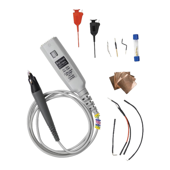
Using the Probes Supplied Accessories The probes come with the accessories shown in Figure 2 on page 9 and listed in Table 2 on page 9. Table 3 on page 10 shows the replacement accessories available in the replacement accessory kit. - Page 9 Using the Probes Figure 2 Probe with Supplied Accessories Table 2 Supplied Accessories Accessory Quantity Accessory Quantity Flex Nose Clip (red) Right-Angle Ground (10 cm) Flex Nose Clip (black) Ground Blade Rigid Probe Tip Offset Ground Spring Probe Tip Flex Ground Y-Lead Adapter (10 cm) Copper Pads Right-Angle Ground (5 cm)
- Page 10 Using the Probes Table 3 Replacement Accessory Kit Part Accessory Number Flex Nose Clip (red) 5061-7390 Flex Nose Clip (black) 5061-7391 Rigid Probe Tip 5061-7389 Spring Probe Tip 5061-7388 Y-Lead Adapter (10 cm) 5061-7392 Right-Angle Ground (5 cm) 5061-7399 Right-Angle Ground (10 cm) 5061-7400 Ground Blade 5061-7393...
-
Page 11: Probe Headlight
Using the Probes Probe Headlight The probe is equipped with a white LED headlight to illuminate the area around the probe tip. This headlight has a fixed intensity and is turned on and off by pressing the button that is located on the probe’s body. -
Page 12: Using The Accessory Tips And Grounds
Recommended Typical Order of Use Probe Configuration Topic Bandwidth “Rigid or Spring Tips with Offset Ground or Ground Blade” 1 GHz (N2795A) page 13 2 GHz (N2796A) “Copper Pads with Flex Ground” on page 15 900 MHz (N2795A) 1.8 GHz (N2796A) “Y-Leads Adapter with 0.1”... - Page 13 Using the Probes Rigid or Spring Tips with Offset Ground or Ground Blade These rigid and spring-loaded tips are replaceable. To change the probe tip, pull it straight out of its contact socket along the axis of the probe. Once the probe tip is removed, the new tip can be inserted into the contact socket along the axis of the probe.
- Page 14 Using the Probes WARNING Handle the probe with care to avoid injury, especially when it is fitted with the sharp rigid or spring tip. When inserting the tip, insert the end with the ridge into the probe head as shown in Figure Figure 5 Inserting the Tips and Grounds...
- Page 15 Using the Probes Copper Pads with Flex Ground These self adhesive copper pads can be attached on top of an IC and connected to its ground pins to create a convenient ground plane for the probe to connect to. When used with the flex ground, this method provides an ideal ground connection for probing signals with high frequency content.
- Page 16 Using the Probes Y-Leads Adapter with 0.1” Headers The Y-lead adapter offers a convenient and reliable method to connect both the probe signal and ground to probe points on the board or other probe accessories. For example, this can used to connect to connector headers or other accessories like the Flex Nose Clip Adapter as seen in the following pictures.
- Page 17 Using the Probes Flexible Nose Clips You can use flexible nose clips to make connections to components or wires with leads that are 1.01 mm (0.04 inches) in diameter or smaller. With today’s miniature IC- and component-packaging techniques, these clips can make probing challenging devices much easier.
- Page 18 Using the Probes Ground Leads and Right-Angle Ground Leads These ground leads can be used to reach grounding locations that are farther away from the probing location than can be reached by either the ground blade or offset ground. However, the longer leads means they have a larger inductance in the ground return path which corresponds to a lower performance than the ground blade and offset ground.
-
Page 19: Dynamic Range And Offset Voltage Limitations
Dynamic Range and Offset Voltage Limitations With 16V (±8V) of dynamic range and ±8V (N2795A) or ±12V (N2796A) of offset range, the probes have a wide measuring range of ±20V, which allows them to be used for a wide variety of applications. -
Page 20: Functional Test
Using the Probes Functional Test Use the following generic measurement procedure to ensure that your probe is functioning properly. 1 Connect the probe to an oscilloscope channel input and ensure the input impedance of the oscilloscope matches the output impedance of the probe (50W). 2 Connect a grounding accessory to the probe and connect the ground to the ground terminal on the oscilloscope. -
Page 21: Inspecting The Probe
• Check the accessories. • If the contents are incomplete or damaged, notify your Keysight Technologies Sales Office. • Inspect the probe. If there is mechanical damage or defect, or if the probe does not operate properly or pass calibration tests, notify your Keysight Technologies Sales Office. -
Page 22: Returning The Probe For Service
Perform the following steps before shipping the probe back to Keysight Technologies for service. 1 Contact your nearest Keysight sales office for information on obtaining an RMA number and return address. 2 Write the following information on a tag and attach it to the malfunctioning equipment. -
Page 23: Safety Information
Using the Probes Safety Information This apparatus has been designed and tested in accordance with IEC 61010-031, Safety requirements for hand-held probe assemblies for electrical measurement and test. Before applying power, verify that the correct safety precautions are taken as described in the following warnings. - Page 24 WARNING To avoid dangerous electric shock, do not attempt to perform any service to the probe. Service should be carried out by a Keysight Technologies authorized service personnel. For any service needs, contact Keysight Technologies. Refer to the topic “Returning the Probe for Service”...
- Page 25 WEEE Directive Annex I, this product is classed as a “Monitoring and Control instrumentation” product. Do not dispose in domestic household. To return unwanted products, contact your local Keysight office, or refer to www.keysight.com for more information. This symbol indicates the Environmental Protection Use Period (EPUP) for the product’s toxic substances for the...
- Page 26 Using the Probes Safety Notices Instruction manual symbol: The product is marked with this symbol when it is necessary for you to refer to the instruction manual in order to protect against damage to the product or personal injury. Earth terminal symbol: Used to indicate a circuit common connected to grounded chassis.
-
Page 27: Characteristics And Specifications
Keysight N2795/6A Single-Ended Probes User’s Guide 2 Characteristics and Specifications This chapter provides the characteristics and specifications for the N2795/6A probes. The probe and oscilloscope should be warmed up for at least 20 minutes before any testing and the environmental conditions should not exceed the probe’s specified limits. - Page 28 < 2.5 mV < 2.5 mV Output Impedance 50Ω 50Ω Internal Power Keysight AutoProbe Interface from scope (InfiniiVision and Infiniium models) a Denotes warranted electrical specification after 20 minute warm-up. All others are typical. b N2796A only Table 7 Mechanical Characteristics...
-
Page 29: Dimensions
Characteristics and Specifications Dimensions N2795/6A User’s Guide... - Page 30 Characteristics and Specifications N2795/6A User’s Guide...
-
Page 31: Performance Data Plots
Keysight N2795/6A Single-Ended Probes User’s Guide 3 Performance Data Plots Figure 11 Frequency Response of N2796A (Vout/Vin) NOTE Figure 11 is for the spring/rigid probe tip and an offset ground or ground blade. - Page 32 Performance Data Plots Figure 12 Input Impedance Over Frequency (Red = measured, Blue = model) N2795/6A User’s Guide...
- Page 33 Performance Data Plots Figure 13 Input Impedance Equivalent Model Figure 14 Typical Input Impedance Plot N2795/6A User’s Guide...
- Page 34 Performance Data Plots N2795/6A User’s Guide...
-
Page 35: Performance Verification
Keysight N2795/6A Single-Ended Probes User’s Guide 4 Performance Verification Test 1. DC Input Resistance Test 2. Bandwidth Performance Test Record These procedures are used to test the warranted specifications for the N2795/6A single-ended active probes. The recommended calibration test interval is once a year or as required. Use the equipment listed in. - Page 36 Table 8 Required Test Equipment Test Equipment Critical Specification Model Number Digital Multimeter (DMM) Resistance ±1% Keysight 34401A Vector Network Analyzer (VNA) 13 GHz sweep range full 2 port cal Option 1D5 Keysight 8720ES Calibration Standards No Substitute Keysight 85052D...
- Page 37 Performance Verification Test 1. DC Input Resistance Procedure 1 Connect the DMM probes between the probe tip and ground at the tip of the probe. 2 Set up the DMM to measure resistance. The resistance should read 1 MW + 0%, –2.5%. 3 Record the resistance in Table 9 on page 47.
-
Page 38: Test 2. Bandwidth
N2795A bandwidth:........ - Page 39 Performance Verification Figure 15 Probe Connected to Probe Adapter (not to scale) Calibrating a Reference Plane To get a reliable measurement from the VNA you must calibrate a reference plane so that the VNA knows where the probe under test is located along the transmission line.
- Page 40 Performance Verification Figure 16 PV/DS Test Board Connected to VNA 8 Press the cal menu screen key. 9 Press the full 2 port screen key. 10 Connect one of the high quality SMA cables to port one and to the pincher side of PV/DS test board. 11 The calibration reference plane is at the other end of PV/DS test board.
- Page 41 Performance Verification 12 Perform a Calibration for the PORT 1 side of the Reference plane. a Press the reflection screen key. b Connect the open end of 85052D Calibration Standard to the non-pincher side of the PV/DS test board. c Select the open screen key under the Forward group. d Wait until the VNA beeps indicating that it has completed the task.
- Page 42 Performance Verification Figure 17 SMA Cable Connected to Port 2 14 Get the opposite sex of the Calibration Standards for the next step. N2795/6A User’s Guide...
- Page 43 Performance Verification 15 Perform Calibration for the PORT 2 side of the Reference plane. a Press the reflection screen key. b Connect the open end of Calibration Standard to the available end of the PORT 2 SMA cable. c Select the open screen key under the Reverse group. d Wait until the VNA beeps indicating that it has completed the task.
- Page 44 Performance Verification Figure 18 Forward and Reverse Setup 18 Press the transmission screen key. 19 Press the do both fwd and reverse screen key. 20 Wait until the VNA beeps four times indicating that it has completed the task. 21 Press the isolation screen key. 22 Press the omit isolation screen key.
- Page 45 Performance Verification 31 Ensure s21 response on screen is flat out to 1 GHz (N2795A) or 2 GHz (N2796A). Measuring Vin Response 32 Position the probe conveniently to allow the probe tip to be normal to the PV/DS board. 33 Hold the probe in position, or use a positioner, so that the signal and ground are making contact and are perpendicular to the fixture.
- Page 46 N2795A bandwidth:........
-
Page 47: Performance Test Record
Recommended next test date: Recommended Test Interval: 1 year / 2000 hours Probe Amplifier Test Limits Result Pass/Fail Test 1. DC Input Resistance 1 MΩ + 0%, –2.5% Test 2. Bandwidth ≥ 1 GHz (N2795A) ≥ 2 GHz (N2796A) N2795/6A User’s Guide... - Page 48 Performance Verification N2795/6A User’s Guide...
- Page 49 12, inspecting, ISM1-A, safety information, service, solderable tip, cable, specifications, CE mark, Keysight Technologies, contacting, spring probe tip, 9, channel identification rings, spring tips, cleaning, supplied accessories, compatibility, compatible oscilloscopes, N5442A adapter, copper pads, 9, temperature,...
Need help?
Do you have a question about the N2795A and is the answer not in the manual?
Questions and answers