
Related Manuals for Extron electronics IN1608 xi IPCP SA with LinkLicense


Summary of Contents for Extron electronics IN1608 xi IPCP SA with LinkLicense
- Page 1 User Guide Scalers IN1608 xi Series Scaling Presentation Switchers 68-2290-02 Rev. A 01 18...
- Page 2 Safety Instructions Istruzioni di sicurezza • Italiano Safety Instructions • English AVVERTENZA: Il simbolo, , se usato sul prodotto, serve ad WARNING: This symbol, ,when used on the product, is avvertire l’utente della presenza di tensione non isolata pericolosa intended to alert the user of the presence of uninsulated dangerous all’interno del contenitore del prodotto che può...
- Page 3 ついては、 エクス トロンのウェブサイ ト より 『Extron Safety www.extron.com and Regulatory Compliance Guide』 (P/N 68-290-01) をご覧ください。 Copyright © 2018 Extron Electronics. All rights reserved. Trademarks All trademarks mentioned in this guide are the properties of their respective owners. The following registered trademarks ( ®...
- Page 4 FCC Class A Notice This equipment has been tested and found to comply with the limits for a Class A digital device, pursuant to part 15 of the FCC rules. The Class A limits provide reasonable protection against harmful interference when the equipment is operated in a commercial environment.
- Page 5 Conventions Used in this Guide Notifications The following notifications are used in this guide: CAUTION: Risk of minor personal injury. ATTENTION : Risque de blessure mineure. ATTENTION: • Risk of property damage. • Risque de dommages matériels. NOTE: A note draws attention to important information. TIP: A tip provides a suggestion to make working with the application easier.
-
Page 7: Table Of Contents
Contents Introduction Operation ............. 25 ........... 1 Front Panel Overview ........25 About this Guide ..........1 Product Description ..........2 Powering Up ............ 26 Integrated Digital Twisted Pair Extension ..2 Input Selection..........26 Video Processing ..........2 On-Screen Menu System ......... 27 Audio Integration Capabilities and Available Front Panel Buttons ........ - Page 8 Configuration Software ........77 Configuration Pages ......... 91 Input and Output Configuration Page .... 92 Software Installation.......... 77 EDID Minder Page ........95 Software Download Center Page ....77 Image Settings Page........97 PCS Product Page ........78 Size and Position Page ......101 Software Connection ........
-
Page 9: Introduction
IN1608 xi MA 70 100 watts 70 V mono power amplifier IN1608 xi IPCP SA Control processor and stereo amplifier IN1608 xi IPCP SA with LinkLicense Control processor and stereo amplifier with LinkLicense UI upgrade IN1608 xi IPCP MA 70... -
Page 10: Product Description
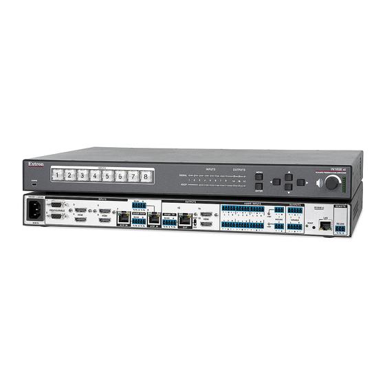
Product Description The Extron IN1608 xi is an HDCP-compliant scaling presentation switcher with four HDMI inputs, two configurable analog video inputs, and two Extron DTP inputs. It includes two HDMI outputs and one DTP/HDBT output, configurable separately. Amplifier models have an integrated Class D audio power amplifier, while IPCP models have a built-in IPCP Pro control processor for complete AV system control. -
Page 11: Features
Features Video Features Video inputs — Four HDMI, two universal 15-pin HD inputs for RGB, component • video, RGBcvS video, S-video, or composite video, two DTP twisted pair inputs on RJ-45, six stereo balanced/unbalanced audio inputs on captive screw, two mic/line audio inputs on captive screw •... -
Page 12: Control Features
Available with energy efficient Class D stereo or mono amplifier: • 2 x 50 watts @ 4 ohms, 2 x 25 watts @ 8 ohms • 1 x 100 watts @ 70 volts — All IN1608 xi power amplifier options feature an •... -
Page 13: General
General Compatible with CATx shielded twisted pair cable — The IN1608 xi fully supports • the maximum specified transmission distance for all compatible resolutions when used with CATx shielded twisted pair cable. Shielded twisted pair cabling with solid center conductor sizes of 24 AWG or better is recommended for optimal performance. The Extron XTP DTP 24 shielded twisted pair cable is recommended for use with the IN1608 xi for optimum signal transmission. -
Page 14: Features Of The Ipcp Models
Auto-Image setup — When activated, causes the unit to automatically optimize the • image by analyzing and adjusting to the video input signal. • Auto Input Memory — When activated, causes the unit to automatically store size, position, and picture settings based on the incoming signal. When the same signal is detected again, these image settings are recalled from memory. -
Page 15: Control Methods
Two bidirectional RS-232 captive screw serial ports that can control two • RS-232 devices • One bidirectional RS-232 captive screw serial port that can communicate with one RS-232 serially controlled device. • Two IR/Serial ports for one-way control of external devices Four digital I/O ports for interfacing with other systems in the room •... -
Page 16: Application Diagrams
Ethernet control via IP Link (IPCP models only), enabling the switcher to be controlled • and actively monitored over a LAN, WAN, or the Internet. Setup of the IPCP control processor, built into IPCP models, requires the Extron Global Configurator Plus or Global Configurator Professional, available for download from the Extron website if you have to have an Extron Insider account. - Page 17 MODEL 80 MODEL 80 Screen Control Laptop Projector HDMI Audio Extron Extron RS-232 HDMI Relay DTP T HWP 4K 331 D DTP T HWP 4K 331 D AUDIO IN Transmitter Transmitter HDMI IN FLAT PANEL FLAT PANEL Flat Panel Display Flat Panel Display OVER DTP RS-232...
- Page 18 Extron Flat Panel Display Screen Control SM 28 Extron MODEL 80 SpeedMount Two-Way TLP Pro 1220TG Projector with Surface Mount Speakers 12" Tabletop HDBaseT Input with 8" Woofer TouchLink Pro Touchpanel Monday, December 16, 2013 7:04 AM Laptop Tuner Contacts Sources 800.633.9876 1 2 3...
-
Page 19: Licensed Third-Party Software Used In The Scalers
Licensed Third-Party Software Used in the Scalers The scalers use various licensed third-party software packages during operation. To view details about third-party packages and associated licensing, click the License button on the page of the internal web pages (see Unit Information Unit Information Information Page... -
Page 20: Installation
Installation This section contains information on how to connect cables to the IN1608 xi models. Topics in this section include: • IN1608 xi Connector Overview • Installation Overview Rear Panel Connections • • Connection Details IN1608 xi Connector Overview All IN1608 xi models feature four HDMI, two DTP, and two universal analog video inputs, along with stereo balanced or unbalanced audio connectors for each input. -
Page 21: In1608 Xi Amplifier Models
IN1608 xi Amplifier Models The IN1608 xi amplifier models (see figure 5) have all the connectors of the standard IN1608 xi plus an amplified audio connector. The SA models feature a 4-pole captive screw connector while the MA models features a 2-pole captive screw connector for amplified audio output. -
Page 22: Installation Overview
Installation Overview Turn off or disconnect all related equipment. Ensure that video sources and output displays are all turned off and disconnected from the power source. Mount the scaler (see Mounting on page 133). Connect input sources (see Power and Input Connections on the next page). -
Page 23: Power And Input Connections
Power and Input Connections IN1608 xi SA AMPLIFIED OUTPUT 2x25W(8Ω)/2x50W(4Ω) INPUTS OUTPUTS AUDIO INPUTS OUTPUTS OVER DTP RS-232 CLASS 2 WIRING 100-240V ~ 1.3 A MAX Tx Rx Tx Rx REMOTE +48V LINK LINK LINK CONFIGURABLE OVER DTP OVER DTP MIC/LINE VARIABLE HDMI... - Page 24 ATTENTION: • Do not connect these connectors to a computer or telecommunications network. • Ne connectez pas ces ports à des données informatiques ou à un réseau de télécommunications. • DTP remote power is intended for indoor use only. No part of the network that uses DTP remote power should be routed outdoors.
-
Page 25: Output Connections
Output Connections IN1608 xi SA AMPLIFIED OUTPUT 2x25W(8Ω)/2x50W(4Ω) INPUTS AUDIO INPUTS OUTPUTS OUTPUTS OVER DTP RS-232 CLASS 2 WIRING 100-240V ~ 1.3 A MAX Tx Rx Tx Rx +48V REMOTE LINK LINK LINK CONFIGURABLE OVER DTP OVER TP MIC/LINE VARIABLE HDMI HDMI RS-232... - Page 26 RS-232 Over TP port — To pass bidirectional serial control, connect a control device to the 5-pole captive screw connector. This port consists of the three poles labeled “RS-232” and shares the ground pole with the IR port. IR Over TP port — To transmit and receive IR signals, connect a control device to the 5-pole captive screw connector.
-
Page 27: Control Connections
Control Connections IN1608 SA AMPLIFIED OUTPUT 2x25W(8Ω)/2x50W(4Ω) INPUTS OUTPUTS AUDIO INPUTS OUTPUTS OVER DTP RS-232 CLASS 2 WIRING REMOTE Tx Rx Tx Rx +48V LINK LINK LINK CONFIGURABLE OVER DTP OVER DTP MIC/LINE VARIABLE 100-240V ~ -- A MAX HDMI HDMI RESET HDMI... -
Page 28: Ipcp Pro 355 Control Processor Connections
IPCP Pro 355 Control Processor Connections The IN1608 xi IPCP models include a built-in IPCP Pro 355 dual-NIC control processor. For these models, the LAN connector is incorporated in the IPCP Pro 355 control processor. For installation details of this control processor, see the IPCP Pro Series User Guide at www.extron.com. -
Page 29: Analog Audio Connection
Analog Audio Connection Wire the audio input and output connectors as shown in figure 16. Use the supplied tie wrap to strap the audio cable to the extended tail of the connector. This does not apply to the amplified audio output connector on the SA and MA models. No Ground Here Ring Sleeves... -
Page 30: Hdmi Connections
HDMI Connections Use an Extron LockIt cable lacing bracket to secure HDMI cables to the device. One bracket secures up to two HDMI cables in a stacked formation (see figure 17), but each stacked formation supports up to two brackets (one on each side) for added support if necessary. Side Mounted Stacked Figure 17. -
Page 31: Serial And Ir Insertion Connections
Serial and IR Insertion Connections IN1608 SA AMPLIFIED OUTPUT 2x25W(8Ω)/2x50W(4Ω) INPUTS OUTPUTS AUDIO INPUTS OUTPUTS OVER DTP RS-232 CLASS 2 WIRING REMOTE Tx Rx Tx Rx LINK LINK LINK +48V CONFIGURABLE OVER DTP OVER DTP MIC/LINE VARIABLE 100-240V ~ -- A MAX HDMI HDMI HDMI... -
Page 32: Twisted Pair Recommendations For Dtp And Hdbaset Communication
Twisted Pair Recommendations for DTP and HDBaseT Communication Use the following pin configurations for shielded twisted pair cables used for DTP or HDBaseT communication. T568B Pins: 12345678 Wire Color White-orange Orange White-green Blue White-blue Green Insert Twisted Pair Wires White-brown RJ-45 Brown Connector... -
Page 33: Operation
Operation This section contains information on the front panel operation, on-screen display menu system, and reset modes of the scalers. Topics in this section include: Front Panel Overview • • Powering Up Input Selection • • On-Screen Menu System • Front Panel Lockout (Executive Modes) Reset Modes •... -
Page 34: Powering Up
Input and output LED indicators Input signal LEDs • — Light for each input when active video content is detected. Output signal LEDs • — Light green when active video is being output or blink amber when video output and sync are disabled from the scaler. Input HDCP LEDs •... -
Page 35: On-Screen Menu System
On-Screen Menu System The on-screen menu is used primarily for the initial setup of the device (for other methods of control, see Control Methods on page 7). The on-screen menu presents configuration options on a local monitor and can be adjusted with front panel controls. NOTE: The on-screen menu has a fixed time-out of 60 seconds. -
Page 36: Using The On-Screen Menu
Using the On-screen Menu Figure 23. On-screen Menu Example To open the on-screen menu: Connect a display device to an HDMI output connector (see figure on page 17). Press the button to open the on-screen menu. Menu Enter To navigate the on-screen menu: >... -
Page 37: Quick Setup Submenu
Quick Setup Submenu Figure 24. Quick Setup Submenu submenu provides quick access to common input, output, and Quick Setup communication settings. This submenu contains the following items: • Auto-Image — Press the button to perform a one-time Auto-Image to size and Enter Auto-Image position the current input (see... -
Page 38: User Presets Submenu
User Presets Submenu Figure 25. User Presets Submenu submenu manages user presets only (input presets are not available User Presets through the on-screen menu). User presets save the current picture control settings for the selected input for recall later or copy settings to other inputs. There are 16 user presets available per input. -
Page 39: Picture Controls Submenu
Picture Controls Submenu Figure 26. Picture Controls Submenu submenu adjusts picture settings. Picture Controls • Image Position — Press the ƒ and „ buttons to select the horizontal ( ) or > < vertical ( ) position of the image. Press the buttons to adjust the value of the selected position. -
Page 40: Input Submenu
Input Submenu Figure 27. Input Submenu (IN1608 xi) submenu adjusts the active input. Input • Auto-Image — Press the button to execute an Auto-Image on the active input. Enter Auto-Image updates active pixel, active lines, horizontal and vertical start, phase, horizontal and vertical image position, and horizontal and vertical image size settings. - Page 41 Input Format — Press the navigation buttons to select an analog video input format • for inputs 1 and 2. All other inputs are digital inputs for HDMI or DVI input signals. The following table shows the available formats for each input. Input 1 Input 2 Input 3...
-
Page 42: Output Submenu
Output Submenu Figure 28. Output Submenu submenu configures the output resolution, refresh rate, HDMI format, and Output HDCP notification. IN1608 xi Scaling Presentation Switcher • Operation... - Page 43 Resolution — Press the navigation buttons to change the resolution and refresh rate • from the select list. The following table shows the available resolution and refresh rates. Resolution 23.98 Hz 24 Hz 25 Hz 29.97 Hz 30 Hz 50 Hz 59.94 Hz 60 Hz 75 Hz 640x480 800x600...
- Page 44 HDMI or TP Output Format — After selecting , or • HDMI 1A Format HDMI 1B Format from the list of submenu items, press the navigation buttons to set the Out 1C Format output format. HDMI output format has three components: Video format —...
-
Page 45: Audio Submenu
Audio Submenu Figure 29. Audio Submenu submenu allows users to adjust audio settings. Extron recommends using the Audio PCS or the internal web pages for initial audio configuration (see Audio Configuration Page on page 102 for more audio configuration details and tips). Audio Mute —... -
Page 46: Advanced Submenu
Gain — Press the navigation buttons to set the gain (in dB) for the active analog or • LPCM-2Ch input. Mic/Line Gain and Phantom — After selecting • from the list of Mic/Line 1 Mic/Line 2 submenu items, press the buttons to select the Mic/Line gain or phantom Left Right... - Page 47 • Test Pattern — Press the navigation buttons to select a test pattern to display or to turn off a test pattern. The available test patterns are Crop Alternating Pixels , and (pink noise). The default setting Color Bars Grayscale Blue Mode Audio Test Figure 31.
- Page 48 Auto Memory — Press the navigation buttons to turn Auto Memory on or off for • each input. The scaler stores 32 auto memories per input, with input configuration and picture control data for each video resolution. The default setting enables these memories to automatically recall input and picture controls for previously applied signals.
-
Page 49: Communication Submenu
Communication Submenu Figure 32. Communication Submenu submenu displays RS-232 settings, current IP configuration (DHCP Communication mode, IP address, Subnet mask, and Gateway address), and MAC address. Press and hold the button for 10 seconds to edit the submenu items listed below. Enter •... -
Page 50: Device Info Submenu
Device Info Submenu Figure 33. Device Info Submenu submenu displays device information including unit name, firmware Device Info version, internal temperature, input and output signal information, detected display information, and RS-232 Insertion status. This submenu does not contain any adjustable submenu items. -
Page 51: Reset Modes
Reset Modes AMPLIFIED OUTPUT 2x25W(8Ω)/2x50W(4Ω) The IN1608 xi series have three reset modes (numbered 1, 4, and 5). OUTPUTS These resets are available by pressing the recessed button on Reset CLASS 2 WIRING the rear panel (see in the image at right). See the Reset Mode REMOTE VARIABLE Summary table for a description of the reset modes. -
Page 52: Rs-232 Insertion
RS-232 Insertion The twisted pair input and output ports allow you to insert RS-232 control signals onto the same cable that carries video and audio to extend them to the Over TP port on a connected endpoint (see figure 34 on the next page and figure 35 on page 46). - Page 53 Network RS-232 Insertion IN1608 xi IPCP SA COM 1 COM 2 COM 3 DIGITAL I/O AV LAN 2 A A LAN 2 AV LAN 3 Tx Rx RTS CTS Tx Rx G Tx Rx G AMPLIFIED OUTPUT 2x25W(8Ω)/2x50W(4Ω) IR/SERIAL RELAYS eBUS -S G PWR OUT = 6W...
-
Page 54: Captive Screw Signal Insertion
RS-232 protocol You also may need to set the RS-232 protocol of the addressed port to match the connected device. You can do this using any of the following methods: Using the Product Configuration Software (see the IN1606 and IN1608 Series PCS Help •... -
Page 55: Sis Configuration And Control
The copyright message is displayed upon connecting to a scaler via TCP/IP or Telnet or after a power cycle via RS-232 and depends on the scaler model. © Copyright YYYY, Extron Electronics, IN1608 xi <model>, Vn.n, 60-nnnn-nn ] (day, date, and time as in... -
Page 56: Password Information
Password Information The ] prompt requires a password (administrator level or user level) followed Password: by a carriage return. The prompt is repeated if the correct password is not entered. If the correct password is entered, the unit responds with ] ] or Login Administrator ] , depending on password entered. -
Page 57: Sis Overview
SIS Overview Using the Command and Response Table Command and Response Table for SIS commands beginning on page 56 lists the commands that the scaler recognizes as valid, the responses that are returned to the host, a description of the command function or the results of executing the command, and examples of commands in ASCII (Telnet). - Page 58 X( = Enable or disable = off or disabled = on or enabled X1) = Input standard = no signal detected on the current input = NTSC 3.85 = PAL = NTSC 4.43 = SECAM = N/A (occurs when the input is active RGB, –...
- Page 59 X2% = Overscan = 0.0% (default for RGB, HDMI) = 2.5% (default for RGBcvS, YUV, S-video, and CV) = 5.0% X2^ = Aspect ratio setting = fill (default) = follow X2& = Screen saver mode = custom color = black output (default) = blue output X2* = Custom screen saver color (black) to...
- Page 60 X4) = IP address xxx.xxx.xxx.xxx = default) 192.168.254.254 X4! = Subnet mask = default) xxx.xxx.xxx.xxx 255.255.0.0 X4@ = Gateway address = default) xxx.xxx.xxx.xxx 0.0.0.0 X4# = MAC address 00-05-A6-xx-xx-xx X4$ = Number of open connections 0-<maximum number of open connections> X4% = Config type = IP config = device-specific parameters...
- Page 61 X5% = Video mute on all outputs 0 = all outputs are unmuted 1 = at least one output is muted 2 = at least one output is muted and sync is disabled X5^ = Volume knob group number = program volume (default) = mic volume = output volume X5&...
- Page 62 X6) = EDID emulation or output = automatic (matches the current output rate resolution, default for EDID emulation only) = output 1A (available for EDID export only) = output 1B (available for EDID export only) = custom EDID or output rate 1 = custom EDID or output rate 2 = custom EDID or output rate 3 = custom EDID/output rate 4...
- Page 63 X6! = Port number = remote port (3-pole captive screw) = UART** on DTP input 7 = UART on DTP input 8 = UART on DTP/HDBT output 1C **UART = universal asynchronous receiver- transmitter X6@ = Baud rate 300, 600, 1200, 1800, 2400, 3600, 4800, 7200, 9600 (default), 14400, 19200, 28800, 38400, 57600, 115200 NOTE:...
-
Page 64: Command And Response Table
Command and Response Table Command ASCII Command Response Additional Description (Host to Scaler) (Scaler to Host) Input Switching Commands Input selection Video and audio X! • Select video and audio from input X! • Video only & Select video-only from input Audio only X! •... - Page 65 Command ASCII Command Response Additional Description (Host to scaler) (Scaler to host) Input Configuration Commands (continued) Input video format Set video format Set input to format View set format View the set video format. In verbose modes 2 and 3: Input EDID Assign EDID to input X6)]...
- Page 66 Command ASCII Command Response Additional Description (Host to scaler) (Scaler to host) Input Configuration Commands (continued) Auto-Image Enable Activate Auto-Image for input Disable Turn off Auto-Image for input View View the Auto-Image setting for In verbose modes 2 and 3: input Execute Execute an Auto-Image for the...
- Page 67 Command ASCII Command Response Additional Description (Host to scaler) (Scaler to host) Input Configuration Commands (continued) Pixel phase (available only for RGB and YUV-HD input signals) Specify a value E X% PHAS Phas Set the pixel phase to on the current input.
- Page 68 Command ASCII Command Response Additional Description (Host to scaler) (Scaler to host) Input Configuration Commands (continued) Active lines E X* Specify a value ALIN Alin Set the active lines to on the current input. Increment value Increase the active lines by one on +ALIN Alin the current input.
- Page 69 Command ASCII Command Response Additional Description (Host to scaler) (Scaler to host) Picture Adjustment Commands (continued) Color (NTSC, PAL, and SECAM inputs only) Specify a value E X1% X1%] Set the color level on the current COLR Colr input. X1%] Increment value Increase the color level by one.
- Page 70 Command ASCII Command Response Additional Description (Host to scaler) (Scaler to host) Picture Adjustment Commands (continued) Horizontal shift (image) Specify a value E X1^ X1^] HCTR Hctr Set the horizontal position to Increment value X1^] Increase the horizontal position by +HCTR Hctr one.
- Page 71 Command ASCII Command Response Additional Description (Host to Scaler) (Scaler to Host) Output Configuration Commands Output Scaler Rate E X6) X6)] Set output rate Set the output resolution and rate RATE Rate X6)] View output rate View the selected output rate. RATE In verbose modes 2 and 3: X6)]...
- Page 72 Command ASCII Command Response Additional Description (Host to Scaler) (Scaler to Host) Output Configuration Commands, continued Screen Saver X2& X2&] Set mode Set the color (mode) of the screen SSAV SsavM X2& saver to X2&] View mode View the color of the screen saver MSSAV X2&...
- Page 73 Command ASCII Command Response Additional Description (Host to Scaler) (Scaler to Host) Audio Configuration Commands (continued) Audio Level Control Set gain or trim X5& X5& X5*] Set the gain of X5& to X5* . View gain or trim X5& X5*] View the gain or trim of X5&...
- Page 74 Command ASCII Command Response Additional Description (Host to Scaler) (Scaler to Host) Audio Configuration Commands, continued Group Volume Set volume X4& X4&] X4& GRPM GrpmD Set the volume to a value of Raise volume X4&] +GRPM GrpmD Increase the volume by Lower volume X4&] -GRPM...
- Page 75 Command ASCII Command Response Additional Description (Host to Scaler) (Scaler to Host) Preset Commands Presets Setting User Preset Input Preset Setting User Preset Input Preset Horizontal and vertical start Saved Film detect Saved Active lines Saved Brightness and contrast Saved Saved Pixel phase Saved...
- Page 76 Command ASCII Command Response Additional Description (Host to Scaler) (Scaler to Host) Preset Commands (continued) Preset Availability ... X( Query input preset View the status of all input presets. availability ... X( PreI Verbose modes 2 and 3 ... X( Query user preset View the status of all user presets.
- Page 77 Command ASCII Command Response Additional Description (Host to Scaler) (Scaler to Host) Advanced Configuration Commands (continued) Front Panel Lockout Mode (executive mode) Enable mode 1 Lock the entire front panel. Exe1 Enable mode 2 Limit front panel control to input Exe2 switching and volume control only.
- Page 78 Command ASCII Command Response Additional Description (Host to Scaler) (Scaler to Host) Advanced Configuration Commands (continued) HDCP Status Query input X3!] HDCP View the HDCP status on input (inputs 3+ only). In verbose modes 2 and 3: X3!] HdcpI Query output X3!] HDCP View the HDCP status on output...
- Page 79 Command ASCII Command Response Additional Description (Host to Scaler) (Scaler to Host) Device Commands On-screen Input “Bug” Timeout The OSD bug is a floating message displayed after selecting a new input. NOTE: Set OSD bug time-out E X2# X2#] Set the duration the OSD bug MDUR Mdur displays to...
- Page 80 Command ASCII Command Response Additional Description (Host to Scaler) (Scaler to Host) Device Commands, continued Information Request General Information X! • X! • X# • X1) • X2( • ... X1# • X1#] Query firmware version View the unit firmware version n.nn (displayed to two decimal places).
- Page 81 Command ASCII Command Response Additional Description (Host to Scaler) (Scaler to Host) IP Control Port Commands IP Setup NOTE: Changes made to any TCP/IP settings do not take effect until the reboot networking command ( 2BOOT } ) is issued. E X( Set DHCP mode Enable or disable DHCP.
- Page 82 Command ASCII Command Response Additional Description (Host to Scaler) (Scaler to Host) IP Control Port Commands, continued Passwords NOTES: • Passwords are case-sensitive. • The pipe ( | ) character is invalid for passwords. • A password cannot be a single space. Set administrator password E X5@ X5@]...
- Page 83 Command ASCII Command Response Additional Description (Host to Scaler) (Scaler to Host) Ethernet to RS-232 Insertion (continued) DTP RS-232 Insertion (continued) DTP RS-232 Output Insertion Parameters (output 3 [1C] only) Enable RS-232 output Set output 3 to RS-232 O 3*0LRPT LrptO 3*0 insertion pass-through.
- Page 84 Command ASCII Command Response Additional Description (Host to Scaler) (Scaler to Host) Ethernet to RS-232 Insertion (continued) Ethernet Data Port Set current connection port X6^] Set the number of seconds before Pti0* timeout the current port timeout to View current connection X6^] View the current port timeout setting port timeout...
-
Page 85: Configuration Software
Configuration Software The Extron Product Configuration Software (PCS) offers another way to control the scalers via USB, or TCP/IP connection. The graphical interface includes the same functions as those on the device front panel with additional features that are available only through the software. -
Page 86: Pcs Product Page
On the Extron website, select the tab (see figure , on the previous Download page). From the left sidebar, click the link ( Software TIP: If PCS is featured in the left sidebar, click the link to go directly to the product page (see “PCS Product Page,”... -
Page 87: Software Connection
In the field (see figure , on the previous page), enter . A drop-down Search menu of selected search results appears under the field. Press < > on the keyboard or select from the drop-down menu. Enter Click the button ( Download Submit any required information to start the download. -
Page 88: Device Discovery Panel
Device Discovery Panel panel displays accessible Extron devices connected directly to Device Discovery the PC or to a LAN or WAN. Devices are identified and sorted by model, IP address, device name, or connection method. Figure 41. Device Discovery Panel To sort the list of available devices: Click the tab (see figure 41,... -
Page 89: Tcp/Ip Panel
Finalize the settings in one of these ways: Click the button to accept the changes and return to the • Apply Device panel. Discovery Click the button to accept the changes and connect to the • Apply and Connect selected device. A new device configuration tab opens. Click the button to cancel any pending changes and return to the •... -
Page 90: Offline Device Preview
Offline Device Preview Opening a new device tab for an offline device displays the interface and configuration options for the chosen model without connecting to it. However, settings cannot be changed. To open a scaler device tab: From the drop-down menu, select Configuration File New Configuration File Figure 43. -
Page 91: Software Overview
Software Overview NOTE: For details about specific software features, see the IN1606 and IN1608 Series PCS Help file. Figure 45. Online Device Tab Each device tab has a drop-down menu for configuration options. The Device Software menu contains software configuration and information options. Software Menu menu (see figure 46) contains options pertaining to PCS settings. - Page 92 Show Expanded Device Tabs This option displays the device IP address or connection method in the tab. Device From the menu, select Software Show Expanded Device Tabs Figure 47. Expanded Device Tab (IN1608 xi Connected through USB) Software Settings This option resets all disabled confirmation dialogs to the default settings. From the menu, select .
- Page 93 About Extron PCS This option contains information about the current PCS version. From the menu, select . The dialog Software About Extron PCS About - Extron PCS box opens. Figure 49. About - Extron PCS Dialog Box Click the button (see figure 49, , for more information).
-
Page 94: Device Menu
Device Menu drop-down menu contains options pertaining to device connection, Device configuration, and information. For details about all these options, see the IN1606 and IN1608 Series PCS Help File. Figure 51. Device Menu • — Disconnects the PCS program from the connected device and closes Disconnect the device tab. - Page 95 — Opens a submenu containing the following restore options: • Restore — Lets you load a saved configuration for the same model • Restore this Device to the connected device. — Lets you load a saved configuration file for the •...
-
Page 96: Internal Web Pages
Internal Web Pages The scalers feature an on-board web server, displayed as a set of internal web pages. These pages allow for control and operation of the scaler through a LAN or WAN connection. Use a web browser to view the pages on a PC connected to the scaler. NOTE: The scaler internal web pages do not support compatibility mode in Microsoft ®... -
Page 97: Turning Off Compatibility Mode
Turning Off Compatibility Mode The internal web pages do not support compatibility mode in Microsoft Internet Explorer. To check compatibility view settings: From the menu of the browser, select . The Tools Compatibility View Settings dialog box opens. Compatibility View Settings Be sure that the checkbox is clear, and Display all websites in Compatibility View... -
Page 98: Auto-Image Button
Auto-Image Button figure Click the button (see , on the previous page) to execute a one- Auto-Image time Auto-Image on the currently selected input. AV Inputs Buttons Click an input button ( ) to select an input. As a new input is selected, the summary within the panel changes to reflect the new statuses. -
Page 99: Video And Audio Mute And Freeze Buttons
Video and Audio Mute and Freeze Buttons • Click the button (see figure , on page 89) to mute only the video Video Mute signal. The button turns red. • Click the button ( ) to globally mute only the audio. The button turns red. Audio Mute •... -
Page 100: Input And Output Configuration Page
Input and Output Configuration Page figure Click the icon on the (see Input/Output Config Global Navigation Bar on the previous page) to open this page. It contains panels for input configuration and output configuration. Input Configuration panel panel consists of user configurable fields for each input. These Input Configuration include (naming),... - Page 101 Aspect ratio From the drop-down menu (see figure , on the previous page), select Aspect Ratio Fill Follow • — Scales the input signal to fill the entire video output. Fill • — Follows the signal aspect ratio, with respect to the current output resolution Follow setting.
- Page 102 Output Configuration panel panel contains controls for output resolution and rate, format Output Configuration settings, switch transitions, and available test pattern selection. Figure 56. Output Configuration Resolution From the drop-down menu (see figure 56, ), select the applicable output Resolution resolution.
-
Page 103: Edid Minder Page
Switch transitions On the panel (see figure , on the previous page), select one of Switch Transitions the following radio buttons: • — Fades video to a black screen before switching to the newly Fade Through Black selected video. — Switches video directly to the newly selected input. •... - Page 104 The EDID properties currently assigned to each input are displayed in the list of inputs. The audio input format listed in an EDID is determined by the audio input format selected on the page (unless a custom EDID is used). Audio Configuration Audio Input Format Audio Capabilities Listed in EDID...
-
Page 105: Image Settings Page
EDID Library and EDID files The EDID Library contains the list of available EDID files. To add EDID files to the EDID Library: Click the ] button (see figure , on page 95). The Upload EDID to Scaler Browse window opens. Add EDID to Library Navigate to the desired EDID file location and select the EDID file. - Page 106 Signal Sampling panel Signal sampling optimizes the input signal to the scaler for the currently selected input. Figure 60. Signal Sampling Panel To manually adjust signal sampling settings, enter a value within the values displayed to the right of each adjustable setting (see figure 60, ) or click the Down arrows.
- Page 107 Overscan panel Overscan mode zooms and crops SMPTE input resolutions to mask edge effects and ancillary data common in broadcast signals. Issuing an Auto-Image with overscan enabled runs an Auto Phase routine (YUV and RGB only) and centers and sizes the input. Figure 62.
- Page 108 Figure 63. Input and User Presets Panels There are 128 presets that are global to all inputs. The presets contain all of the settings for an input when used with an upstream matrix switcher. Input presets save signal type, signal sampling, and picture control settings.
-
Page 109: Size And Position Page
Size and Position Page page provides three methods of adjusting image output size and Size and Position position: graphically, numerically, or automatically with Auto-Image. Click the Size and icon (see figure , on page 91) on the to open Position Global Navigation Bar page. -
Page 110: Audio Configuration Page
Audio Configuration Page From the page, audio inputs and outputs are configured and mixed. Audio Configuration Click the icon (see figure , on page 91) on the Audio Config Global Navigation to open this page. There are four tabs for adjusting program and microphone inputs, mixing inputs, and configuring outputs. - Page 111 Line input configuration tab contains options to set the audio input format for each input and adjust Line Input the input gain for analog inputs. Figure 66. Line Input Tab Audio format The audio input format specifies whether the audio input is analog, digital, or not to be sent to the output.
- Page 112 To select an audio format: Click the tab (see figure , on the previous page). Line Input From the drop-down menu ( ) of the each input, select the desired Audio Format format. Input gain fader can apply to analog or digital gain depending on the input. It has a Input Gain gain range of -18 dB to +24 dB.
- Page 113 To optimize input gain with pink noise: Click the tab (see figure on page 103). Line Input For the web pages only: if necessary, select the checkbox ( Enable Meters NOTE: Meters are automatically enabled on the PCS. Set the input gain so the meters read approximately -20 dBFS. If the audio source has an output level setting control, set the output of the player to the maximum or 0 dB of attenuation.
- Page 114 Phantom power Phantom power adds +48 VDC to the mic/line input. The default level for the microphone input is 0 dB, muted. Having the input muted before plugging in a microphone and especially before turning on phantom power is recommended. ATTENTION: •...
- Page 115 To optimize the mic/line gain on each microphone input: Connect the desired microphone and route the mic/line input to the desired output. Phantom power If needed, click the button (see on the previous Phantom Power page). Set the mic/line fader to 0 dB. Gain If the mic/line input is muted (the button is red when the audio is muted), click the...
- Page 116 figure In the field (see on page 105), adjust the value by one of the Hold Time following methods: Enter a value in the field and press the < > or < > key. • Hold Time Enter Click the arrow buttons.
- Page 117 Mic mix levels Mic mix levels adjust the individual mic levels to create a proper blend (mix) of the two microphones. Adjust the fader to adjust the desired mic/line level. Mic 1 Mic 2 To adjust the mic mix levels: Click the tab (see figure 68...
- Page 118 To adjust the program volume: Click the tab (see figure , on page 108). Mix Controls Adjust the level using any of the following methods ( Click and drag the fader handle to the desired level. • Click in the level text field below the fader and enter a new value. Then, press the •...
- Page 119 To optimize the program volume: With the amplifier turned off, connect the Variable output of the scaler to an amplifier of appropriate size for the room and the speakers. Set the amplifier input level to a moderate level (for example, the twelve o’clock position on the amplifier dial).
- Page 120 Output configuration tab contains options to apply a limiter, set mix options, or adjust output gain. Output Each output has a panel containing these options, but each panel may appear slightly different depending on the scaler model. Figure 70. Amplified Audio Output Panel (SA Models) Figure 71.
- Page 121 Figure 74. Digital Audio Output Panel The digital output section displays the detected audio format sent to the HDMI or twisted pair output (see Audio format on page 103). NOTE: If the detected format is audio, the faders and Multi-Ch Left Right meters are not applicable.
- Page 122 In the panel (see figures 71 and , on page 112), click the desired Mix Options radio button. The amplifier models have different options based on the type of amplified audio output connector. For stereo models, the mix options include the following: •...
- Page 123 For digital outputs (HDMI 1A, HDMI 1B, and Out 1C): Click the tab (see figure , on page 102). Output If desired, select the checkbox in the panel (see figure Mic/Line Mix Options on page 113) to include the mic/line inputs in the output. In the panel ( ), click the desired radio button:...
- Page 124 Group masters The IN1608 xi includes eight pre-configured group masters that allow multiple group members to be adjusted using a single group master control (see the table below for a description of each group master and the associated group members). Group masters provide a convenient way to adjust multiple controls simultaneously.
- Page 125 NOTES: • Amplified output is for amplifier and IPCP models only. • By default, all possible group members are selected for groups 1-7. • The default selected group members for group 8 are amplified output (amplifier and IPCP models only) and variable analog output. To configure the groups: Click the tab (see...
- Page 126 Group controls When grouped, gain control members move together at relative levels. If one member reaches its limit, it retains that position while the other members continue to travel. When the grouped members travel in the reverse direction, the member that was at its limit reverts to its position relative to the other members.
-
Page 127: Preset Management Page
Preset Management Page page gives access to input and user presets. Click the Preset Management Preset icon (see figure on page 91) on the to open Management Global Navigation Bar page. (The preset management functions available on this page Preset Management Input Presets are duplicated in the panel on the... - Page 128 On the confirmation dialog box, click the button (see figure , on Overwrite the previous page) to erase the previous data and save the new settings, or click the button ( ) to return to the page. Cancel Preset Management To recall a preset: Select the input preset or user preset (see figure...
-
Page 129: Device Settings Page
Device Settings Page page allows configuration of screen saver settings, auto switch Device Settings modes, HDCP notifications, video and sync muting, on-screen display timeout, HDCP modes, and RS-232 insertion modes. Click the icon (see figure Device Settings on page 91) on the to open the page (see Global Navigation Bar... - Page 130 — Lets you select a screen color that is displayed when the screen saver is • Custom enabled. Do either of the following: Click the desired screen color in the swatch table. The RGB value of the • selected color is displayed in the field.
- Page 131 HDCP Mode panel HDCP mode either follows the encryption status of the selected input or always encrypts the output. However, some sink devices require continuous DVI authentication trials to pass HDCP encrypted content after a power cycle or resuming from sleep mode. Select one of the following radio buttons (see figure , on page 121):...
-
Page 132: Hardware Pages
Insertion Port — This column lists the insertion port numbers. The insertion port • number must be stated from a specific starting point. This number is automatically entered as the Telnet port number when you establish communication with the insertion port. -
Page 133: Device Name Page
Figure 82. License Information Dialog Box To view a copy of a listed package license, click the link in the column for the relevant License package (see Licensed Third-Party Software Used in the Scalers on page 11). Device Name Page page allows you to assign or change the name or hostname of the Device Name connected device. -
Page 134: Communication Settings Page
Communication Settings Page page contains options to adjust device settings for Communication Settings RS-232 and Ethernet connections. Click the icon (see Communication Settings figure on page 124) on the to open the page. Global Navigation Bar Figure 84. Communication Settings Page RS-232 settings From the drop-down menu (see figure 84,... -
Page 135: Update Firmware Page
Update Firmware Page page provides a means of uploading firmware files to the connected Firmware Loader scaler. Click the icon (see figure , on page 124) on the Update Firmware Global to open this page. Navigation Bar Figure 85. Update Firmware Page If necessary, download firmware updates from www.extron.com. -
Page 136: Executive And Power Mode Page
Executive and Power Mode Page page contains options for enabling or disabling the front Executive and Power Mode panel lockout and power modes. Click the icon (see figure Exec/Power Mode page 124) on the to open the page. Global Navigation Bar Figure 87. -
Page 137: Date And Time Page
Date and Time Page page contains adjustable device date and time settings. Click the Date and Time Date icon (see figure , on page 124) on the to open and Time Global Navigation Bar the page. Figure 88. Date and Time Page To automatically sync the date and time to a connected PC: Click the button (see figure 88,... -
Page 138: Password Page
Click the button to accept the new settings, or click the button to exit Cancel the dialog box. NOTE: Alternatively, click the Previous Month Next button on the far left and right of the month and Month year to cycle through dates. Select the day. -
Page 139: Reset Device Page
To create or change an administrator password: In the field (see figure , on the previous page) enter Administrator Password the desired administrator password. In the field ( ), reenter the administrator password. Confirm Password NOTE: Select the checkbox ( ) to display the password characters. - Page 140 NOTES: • The default IP address is 192.168.254.254 • The default DHCP setting is To reset the device: Click the radio button of the desired reset option (see figure , on the previous page). Click the button ( ). A confirmation dialog box opens. Apply In the dialog box, click the button to continue with the reset, or the...
-
Page 141: Reference Information
Reference Information This section provides reference or supplemental information. Topics in this section include: Mounting • • Downloading Updated Firmware Mounting Tabletop Mounting Attach the provided rubber feet to the bottom four corners of the enclosure. Rack Mounting Mount the scalers into racks with the pre-installed rack ears (see UL Guidelines for rack mounted devices on the next page). -
Page 142: Furniture Mounting
UL Guidelines for rack mounted devices The following Underwriters Laboratories (UL) guidelines pertain to the safe installation of the scaler in a rack. Elevated operating ambient temperature — If the equipment is installed in a closed or multi-unit rack assembly, the operating ambient temperature of the rack environment may be greater than room ambient temperature. -
Page 143: Downloading Updated Firmware
Downloading Updated Firmware Figure 95. Downloading Firmware from the Extron Website Extron website, click the On the tab (see figure 95, Download On the left sidebar, click the link ( Firmware Navigate to the model ( IN1608 xi Ensure the available firmware version is a later version than the current one on the device. - Page 144 Extron Electronics makes no further warranties either expressed or implied with respect to the product and its quality, performance, merchantability, or fitness for any particular use. In no event will Extron Electronics be liable for direct, indirect, or consequential damages resulting from any defect in this product even if Extron Electronics has been advised of such damage.
Need help?
Do you have a question about the IN1608 xi IPCP SA with LinkLicense and is the answer not in the manual?
Questions and answers