Table of Contents
Advertisement
Quick Links
IN1608 Series • Setup Guide
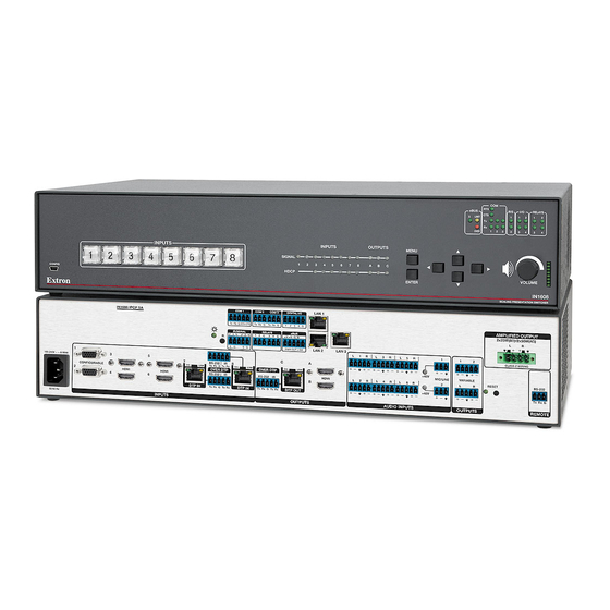
The Extron IN1608 Scaling Presentation Switcher is an eight input, HDCP-compliant video scaler that accepts a wide variety of audio and video
formats. This guide allows an experienced user to set up and configure IN1608, IN1608 SA, IN1608 MA, IN1608 IPCP SA, and IN1608 IPCP MA 70
scalers. It covers how to perform basic operations using the front panel controls and selected Simple Instruction Set (SIS™) commands.
NOTE:
For full installation, configuration, menus, connector wiring, and operation details, see the IN1606 and IN1608 Series User Guide, at
www.extron.com. For installation, configuration, and operation details of the IPCP Pro 350 control processor, see the IPCP Pro Series
User Guide.
Installation
IN1608 Series Rear Panel Connectors
IN1608 IPCP SA
1
100-240V ~ 1.5 A MAX
3
CONFIGURABLE
2
HDMI
4
50/60 Hz
A
B
Power and Input Connections
A
AC power connector
B
Configurable analog 15-pin HD (VGA) connectors (inputs 1 and 2)
C
HDMI input connectors (inputs 3 through 6)
D
DTP input and corresponding RS-232/IR Over DTP connectors
(inputs 7 and 8)
E
Analog audio input connectors (associated with inputs 1 through 6)
F
Mic/Line audio input connectors and adjacent phantom power LEDs
Figure 1.
IN1608 Series Rear Panel Connectors (IN1608 IPCP SA Shown)
The IN1608 IPCP models feature a built-in Extron IPCP Pro 350 control processor for controlling and monitoring a variety
of external devices, such as projectors and lights. See the IPCP Pro Series Setup Guide for more details.
NOTE:
The non-IPCP models have a LAN connector next to the Remote RS-232 connector (see
right) instead of the IPCP Pro 350 control processor.
Mounting and Cabling
Step 1 — Mount the device
a.
Turn off or disconnect all equipment
power sources.
b.
Mount IN1608 scalers to a rack
using the pre-installed rack ears
or use an optional mounting kit
for under-the-desk mounting (see
the two images to the right). The
IN1608 comes in a 1U, full rack width
enclosure. All other IN1608 models
come in 2U, full rack width enclosures.
COM 1
Tx Rx
G
RTS CTS
IR/SERIAL
1
2
R
S G
S G
5
7
RS-232
IR
8
Tx Rx
G
Tx Rx
SIG
LINK
SIG
LINK
OVER DTP
HDMI
RS-232
IR
6
DTP IN
DTP IN
Tx Rx
G
Tx Rx
INPUTS
C
D
Rack Mounting
IMPORTANT:
Refer to www.extron.com for the complete
user guide, installation instructions, and
specifications before connecting the
product to the power source.
L
LAN 1
COM 2
COM 3
DIGITAL I/O
Tx Rx
G
Tx Rx
G
1
2
3
4 G
RELAYS
eBUS
1 2 C
3 4 C
+ V + S - S G
PWR OUT = 6W
LAN 2
LAN 3
L
1
R
C
A
SIG
LINK
OVER DTP
HDMI
L
2
R
RS-232
IR
B
DTP OUT
Tx Rx
G
Tx Rx
OUTPUTS
G
H
Output Connections
G
DTP output connector and
corresponding RS-232/IR Over
DTP connector (output C)
H
HDMI output connectors
(outputs A and B)
I
Analog audio output connectors
J
Amplified audio output connector
(SA, MA, and IPCP models only)
Rack Ears
AMPLIFIED OUTPUT
2x25W(8Ω)/2x50W(4Ω)
L
3
R
L
5
R
1
1
2
+48V
MIC/LINE
VARIABLE
L
4
R
L
6
R
RESET
2
L
R
+48V
AUDIO INPUTS
OUTPUTS
E
F
I
Control Connections
K
Remote RS-232
connector
L
IPCP Pro 350 control
processor (IPCP
models only)
M
LAN connector
(IN1608, SA, and MA
models only)
O
OUTPUTS
1
2
M
to the
VARIABLE
L
R
Mounting Screws
(2) Places
Each Side
#8 Screw
(4) Places
MBU 149
Each Side
Mounting Bracket
Furniture Mounting
J
L
R
CLASS 2 WIRING
RS-232
Tx Rx
G
REMOTE
K
M
AMPLIFIED OUTPUT
2x25W(8Ω)/2x50W(4Ω)
L
R
CLASS 2 WIRING
REMOTE
LAN
RESET
RS-232
Tx Rx
G
IN1608 SA
1
Advertisement
Table of Contents

Related Manuals for Extron electronics IN1608 IPCP SA


Summary of Contents for Extron electronics IN1608 IPCP SA
- Page 1 The Extron IN1608 Scaling Presentation Switcher is an eight input, HDCP-compliant video scaler that accepts a wide variety of audio and video formats. This guide allows an experienced user to set up and configure IN1608, IN1608 SA, IN1608 MA, IN1608 IPCP SA, and IN1608 IPCP MA 70 scalers.
- Page 2 Signal LED — Lights green when the IN1608 is outputting active video to a DTP receiver. Link LED — Lights amber when a valid link is established between the IN1608 and a DTP receiver. To pass serial, infrared data, or other control signals to a DTP device, connect a control device to the RS-232 and IR Over DTP captive...
- Page 3 Wire the audio input and output connectors as shown below and to the right. Use the supplied tie wrap to strap the audio cable to the extended tail of the connector. This does not apply to the amplified audio output connectors on the IN1608 SA, IN1608 MA, or IN1608 IPCP models.
-
Page 4: Firmware Upgrades
Basic SIS Command Table IN1608 scalers can be configured with specific SIS commands via an RS-232, USB, or Ethernet connection. Use the Extron DataViewer utility or a control system to send and receive SIS commands. The table below lists a selection of SIS commands. For a full list of SIS commands and variables, see the IN1606 and IN1608 Series User Guide at www.extron.com.
Need help?
Do you have a question about the IN1608 IPCP SA and is the answer not in the manual?
Questions and answers