Table of Contents
Advertisement
Quick Links
Advertisement
Table of Contents

Related Manuals for Extron electronics IN1502


Summary of Contents for Extron electronics IN1502
- Page 1 IN1502 Video Scaler 68-1205-01 Rev. D 02 08...
- Page 2 Precautions Safety Instructions • English Warning Power sources • This equipment should be operated only from the power source indicated on the product. This This symbol is intended to alert the user of important operating and maintenance equipment is intended to be used with a main power system with a grounded (neutral) conductor. The (servicing) instructions in the literature provided with the equipment.
- Page 3 FCC Class A Notice This equipment has been tested and found to comply with the limits for a Class A digital device, pursuant to part 15 of the FCC Rules. These limits are designed to provide reasonable protection against harmful interference when the equipment is operated in a commercial environment. This equipment generates, uses and can radiate radio frequency energy and, if not installed and used in accordance with the instruction manual, may cause harmful interference to radio communications.
- Page 5 Rear panel video output MENU Output 15-pin HD connector ADVANCED CONFIG Step 5 MENU Plug the IN1502 and input and output devices into a EXIT MENU MENU grounded AC source, and turn on the input and NEXT output devices. Step 6...
- Page 6 QS-2 IN1502 • Quick Start...
-
Page 7: Table Of Contents
About this Manual ......................1-2 About the IN1502 ......................1-2 What is the IN1502? ......................1-2 Controlling the IN1502 video scaler ................1-2 Features and Options ...................... 1-2 Features ..........................1-2 Options and accessories ....................1-3 Chapter 2 • Installation and Operation .............. - Page 8 Part Numbers and Accessories ................. A-4 Included parts ........................A-4 Accessories ........................A-4 Firmware Upgrade Installation ................. A-5 All trademarks mentioned in this manual are the properties of their respective owners. 68-1205-01 Rev. D 02 08 IN1502 • Table of Contents...
-
Page 9: Chapter 1 • Introduction
IN1502 Chapter One Introduction About this Manual About the IN1502 Features and Options... -
Page 10: About This Manual
About the IN1502 What is the IN1502? The IN1502 is a video scaler that offers 16 output rates and provides scaling solutions for boardrooms, conference rooms, and home theaters, as well as rental and staging applications. -
Page 11: Options And Accessories
A similar process is used for PAL film-source video. Versatile mounting options — The IN1502 is 1U high, and a half rack wide. It is rack mountable, or it can be placed on a table or other furniture. Rubber feet are included. - Page 12 Introduction, cont’d IN1502 • Introduction...
-
Page 13: Chapter 2 • Installation And Operation
IN1502 Chapter Two Installation and Operation Mounting the Scaler Rear Panel Features Front Panel Features Menus, Configuration, and Adjustments Optimizing the System for a DVD Player Input Reset System Reset Front Panel Security Lockout (Executive Mode) IR 901 Infrared Remote Control... -
Page 14: Mounting The Scaler
If feet were installed on the bottom of the IN1502, remove them. Place the IN1502 on one half of the 1U (one unit high, one unit wide) rack shelf (part #60-190-01 or #60-604-01). Align the front of the IN1502 with the front of the shelf, and align the threaded holes on the bottom of the IN1502 with the holes in the rack shelf. - Page 15 1 through 3. Attach the rack shelf to the rack using four 10-32 x ¾" bolts (provided). Insert the bolts through #10 beveled washers, then through the holes in the rack, as shown above. IN1502 • Installation and Operation...
-
Page 16: Application Diagram
Installation and Operation, cont’d Application diagram The diagram shown below is an example of a typical IN1502 application with cable connections. RS-232 Control VI DE SI TE M PO IN1502 Video Scaler LCD Projector Application diagram example of the IN1502... -
Page 17: Rear Panel Features
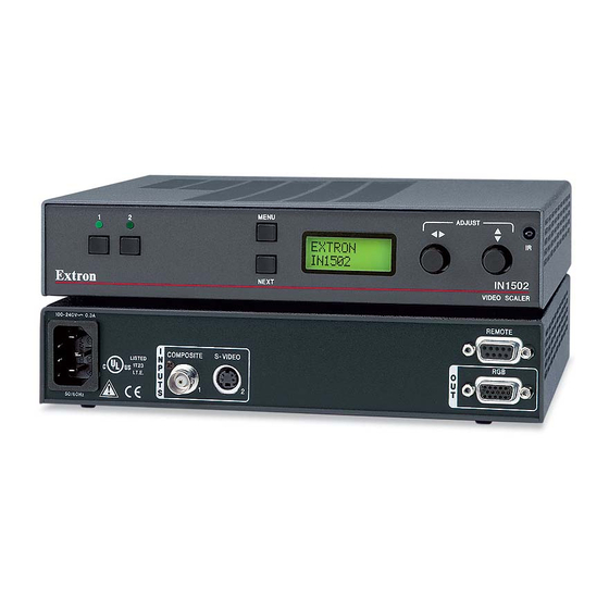
Rear Panel Features The rear panel of the IN1502 is shown below. REMOTE 100-240V 0.3A COMPOSITE S-VIDEO 50/60 Hz IN1502 rear panel connectors AC power connector — Plug a standard IEC power cord into this connector to connect the scaler to a 100 to 240 VAC, 50 Hz or 60 Hz power source. -
Page 18: Front Panel Features
Menu button Menu button — Use this button to enter and move through the main menu system in the IN1502. See the “Menus, Configuration, and Adjustments” section in this chapter for details. LCD menu display and controls LCD —... -
Page 19: Menus, Configuration, And Adjustments
Menus, Configuration, and Adjustments Scaler configuration and adjustments can be performed by using the front panel controls and the menus that are displayed on the IN1502’s LCD screen. These menus are used primarily when the scaler is first set up. - Page 20 MENU NEXT Main menus To return to the default screens, let the IN1502 time-out for 10 seconds, or press the Menu button until the Exit Menu menu appears, then press the Next button. Submenus are accessed from a main menu by pressing the Next button. If you press the Menu button while a submenu is active, the next main menu becomes active.
-
Page 21: Picture Control
This submenu allows adjustment of the image detail (sharpness) of the output display. The adjustment ranges from 0 to 63. The default is 16. Using either the horizontal Adjust ( ) or vertical Adjust ( ) knob, adjust the detail while observing the output display. IN1502 • Installation and Operation... -
Page 22: Output Configuration
To output composite sync, select “HV” as the H Format. Select “H” to output horizontal sync. Select either H or HV by rotating either the horizontal Adjust ( ) or vertical Adjust ( ) knob. The default is “H”. 2-10 IN1502 • Installation and Operation... -
Page 23: Advanced Configuration
Input 2 is selected. From this submenu, use either the horizontal Adjust ( ) or vertical Adjust ( ) knob to specify this mode as “On” or “Off”. The default is “Off”. IN1502 • Installation and Operation 2-11... -
Page 24: 2:2 Pulldown Detection (Pal Film Mode Detect) Submenu
DVD player will defeat the advantage of having 3:2 pulldown detection in the IN1502. All sizing adjustments to correct aspect ratio should be done using the IN1502. To change the output aspect ratio of most DVD players, Enter the DVD player’s Setup or Action menu while the disc is stopped. -
Page 25: Input Reset
“Autoswitch (Autosw) mode” in the “Advanced Configuration” section of this chapter. System Reset To reset the IN1502 to all of its default values, hold down the Input 1 button while simultaneously plugging in the power cord. The System Reset message is displayed on the LCD screen. -
Page 26: Ir 901 Infrared Remote Control
Executive mode has been enabled on the IN1502, input selection and adjustments can still be made from the IR 901. You must use the IN1502’s front panel, a host computer, or an RS-232 control device to configure and program the scaler. See chapter 3, “Serial Communication”, for details. -
Page 27: Troubleshooting
Troubleshooting This section gives recommendations on what to do if you have problems operating the IN1502, and it provides examples and descriptions for some image problems you might encounter. The following are some tips to help you in troubleshooting. Some symptoms may resemble others, so you may want to look through all of the examples before attempting to solve the problem. - Page 28 Installation and Operation, cont’d 2-16 IN1502 • Installation and Operation...
-
Page 29: Chapter 3 • Serial Communication
IN1502 Chapter Three Serial Communication RS-232 Programmer’s Guide... -
Page 30: Rs-232 Programmer's Guide
When the scaler receives a valid SIS command, it executes the command and sends a response to the host device. If the IN1502 is unable to execute the command because the command is invalid or it contains invalid parameters, it returns an error response to the host. -
Page 31: Using The Command/Response Tables
0 = none 1 = NTSC 3.58 2 = PAL 3 = NTSC 4.43 4 = SECAM = Blanking adjustment range (0 through 127 lines) = Scaler refresh rate 1 = 50 Hz 2 = 60 Hz IN1502 • Serial Communication... -
Page 32: Command/Response Table For Sis Commands
View the brightness value Show the current brightness adjustment level. Detail mode Set the detail level Set the detail level to Increment Increment the detail setting. Decrement Decrement the detail setting. View the detail value Show the detail setting. IN1502 • Serial Communication... - Page 33 View the output rate Show the scaler output rate. Video mute Mute on Vmt 0 Mute video output. Example: Vmt0 Mute off Vmt 1 Unmute video output. View video mute status Show the video mute status. IN1502 • Serial Communication...
- Page 34 Show the scaler’s input number and signal standard. Zap (reset to default settings) Total reset zXXX ZapXXX Reset everything: all settings and adjustments to the factory default. Image adjustment reset ZapI Reset image adjustments to factory settings. IN1502 • Serial Communication...
-
Page 35: Command/Response Table For Special Function Sis Commands
Set to horizontal sync 15*1# HFm0 Set H format to off/0 (horizontal sync, default). Set to composite sync 15*0# HFm1 Set H format to on/1 (composite sync). View H Format status Show H format mode status. IN1502 • Serial Communication... - Page 36 Serial Communication, cont’d IN1502 • Serial Communication...
-
Page 37: Appendix A • Appendix
IN1502 Appendix Appendix Specifications Part Numbers and Accessories Firmware Upgrade Installation... -
Page 38: Specifications
Serial control pin configurations 2 = TX 3 = RX 4 = input 1 select (contact closure) 5 = GND 6 = input 2 select (contact closure) Contact closure ......9-pin female D connector (same as RS-232 connector) IN1502 • Appendix... - Page 39 Listings .......... UL, CUL Compliances ......... CE, FCC Class A, VCCI, AS/NZS, ICES MTBF ..........30,000 hours Warranty ........3 years parts and labor All nominal levels are at ±10%. Specifications are subject to change without notice. IN1502 • Appendix...
-
Page 40: Part Numbers And Accessories
Appendix, cont’d Part Numbers and Accessories Included parts These items are included in each order for a IN1502 scaler: Included parts Part number IN1502 60-726-01 Rubber feet (self-adhesive) (4) IEC power cord Tweeker (small screwdriver) IN1502 User’s Manual Accessories These items can be ordered separately:... -
Page 41: Firmware Upgrade Installation
Some IN1502 firmware updates must be performed at the Extron factory. Follow these steps to replace firmware in the scaler. Disconnect the AC power cord from the IN1502 to remove power from the unit. To prevent electric shock or damage, always unplug the IN1502 scaler from the AC power source before opening the enclosure. - Page 42 Gently, but firmly, press the chip into place in the socket. Replace the top cover on the IN1502 scaler, and fasten it with the screws that were removed in step 3. Rack or furniture mount the scaler, and reconnect the AC power cord.
- Page 43 Extron’s Warranty Extron Electronics warrants this product against defects in materials and workmanship for a period of three years from the date of purchase. In the event of malfunction during the warranty period attributable directly to faulty workmanship and/or materials, Extron Electronics will, at its option, repair or replace said products or components, to whatever extent it shall deem necessary to restore said product to proper operating condition, provided that it is returned within the warranty period, with proof of purchase and description of malfunction to:...
- Page 44 Extron Electronics, Asia Extron Electronics, USA Extron Electronics, Europe Extron Electronics, Japan 135 Joo Seng Rd. #04-01 1230 South Lewis Street Beeldschermweg 6C Kyodo Building, 16 Ichibancho PM Industrial Bldg., Singapore 368363 Anaheim, CA 92805 3821 AH Amersfoort, The Netherlands Chiyoda-ku, Tokyo 102-0082 +800.7339.8766 +65.6383.4400 800.633.9876 714.491.1500...
Need help?
Do you have a question about the IN1502 and is the answer not in the manual?
Questions and answers