Extron electronics ISS 506 Setup Manual
Hide thumbs
Also See for ISS 506:
- Specification sheet (3 pages) ,
- User manual (182 pages) ,
- Installation manual (17 pages)
Advertisement
Quick Links
ISS 506 • Setup Guide (Continued)
ISS 506 • Setup Guide
NOTE: For full installation, configuration, and operation details, refer to
the ISS 506 User Guide, available at www.extron.com.
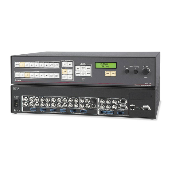
This guide provides quick start instructions for an experienced installer to set up and operate the
Extron ISS 506 Integration Seamless Switchers, a family of seamless, scaling, video and stereo audio switchers.
Installation and Cabling Features
2
Rear Panel
1
R/
G/Y
B/C
V
3
100-240V
H/HV
R-Y
VID
B-Y
50/60 Hz
2A MAX
I
N
2
4
P
U
T
R/
G/Y
B/C
V
H/HV
S
R-Y
VID
B-Y
1
2
L
R
L
R
L
1
Connections
a
AC power connector
b
Inputs 1 through 4 configurable BNC connectors
(RGB, component, RGBcvS, S-video, or composite)
c
Input 5 configurable BNC connectors
(component, S-video, composite)
d
Input 6 configurable mini-DIN and BNC connectors
(S-video, composite, SDI/HD-SDI*, auto SDI)
e
Input 1 through 6 audio captive screw connectors
f
Program Output BNC connectors
(RGB or component)
g
Program Output 15-pin HD connector
(RGB or component)
*
An SDI or HD-SDI input is preset only when an optional SDI or HD-SDI input card is installed (DI/DVI, DI/SC, and DI/3G-SDI models).
i
The output for
†
Step 1 — Mounting
Turn off or disconnect all equipment power sources. For tabletop use, affix
the rubber feet. For optional rack mounting, secure the supplied brackets
(see image at right) and mount in a rack.
Step 2 — Video inputs
a.
Inputs 1 through 4 — Connect RGB video, component video,
S-video, or composite video to these female BNC connectors.
Input 1 through 4 Configurations
R/
R-Y
RGBHV
Video
R/
RGBS or
R-Y
RGBcvS
Video
R/
RGsB or
R-Y
Component
Video
b.
Input 5 — Connect NTSC or PAL component video,
S-video, or composite video to these female BNC
connectors as shown at right.
3
4
R/
G/Y
B/C
V
5
5
VID
VID
6
6
VID
H/HV
SDI
SDI
R-Y
VID
B-Y
/Y
/Y
R
O
R-Y
U
T
P
B-Y
H
R/
G/Y
B/C
V
R-Y
YC
H/HV
U
R-Y
VID
B-Y
/C
T
S
3
4
5
6
FIXED
R
L
R
L
R
L
R
L
5
depends on the optional output card installed (DI/DVI, SC, DI/SC, and DI/3G-SDI models).
G/Y
B/C
V
H/HV
B-Y
VID
G/Y
B/C
V
H/HV
VID
B-Y
B/C
V
G/Y
H/HV
VID
B-Y
6
8
DVI
9
DVI
OUT
PREVIEW
PROGRAM
RGB/R-Y, Y, B-Y
G
B/
LAN
/Y
RGB/R-Y, Y, B-Y
RGB/R-Y, Y, B-Y
RS232/422
B-Y
RESET
V
S
PREVIEW
PREVIEW
PROGRAM
PROGRAM
VARIABLE
R
L
R
L
R
10
7
11
13 12
h
Preview Output 15-pin HD connector
(RGB or component)
i
Optional Program Output connector(s)
(DVI, scan converted low resolution, or 3G/HD-SDI
j
Output audio captive screw connectors
k
LAN (Ethernet) RJ-45 port
l
RS-232/422 DB-9 port
m
Reset button
n
Configuration port (front panel)
(RS-232 only on a 2.5 mm TRS connector)
R/
G/Y
R-Y
VID
S-Video
R/
G/Y
VID
R-Y
Composite
Video
Input 5 Configurations
5
VID
/Y
B-Y
R-Y
/C
Component Video
Front Panel
C
VID
Y
LO-
ADJUSTMENTS
RES
R-Y/
Y/
B-Y/
OUT
R
G
B
Scan Converter
SIZE
POSITION
3G/HD-SDI
OUT
3G/HD-SDI
MBD 249
2U Rack Mount Bracket
(use four lower holes)
B/C
V
H/HV
B-Y
B/C
V
H/HV
B-Y
5
VID
5
VID
/Y
/Y
B-Y
R-Y
R-Y
/C
S-Video
Composite Video
PICTURE
BRIGHT/
DETAIL
CONT
COLOR/
ZOOM
TINT
CONFIG
14
)
†
B-Y
/C
Advertisement

Related Manuals for Extron electronics ISS 506


Summary of Contents for Extron electronics ISS 506
- Page 1 ISS 506 User Guide, available at www.extron.com. This guide provides quick start instructions for an experienced installer to set up and operate the Extron ISS 506 Integration Seamless Switchers, a family of seamless, scaling, video and stereo audio switchers. Installation and Cabling Features...
- Page 2 BNC connectors (shown below). If an optional program output board is installed DVI Video Program Output Configurations (see the ISS 506 User Guide, available at www.extron.com), connect a DVI-D (shown at right), 3G/HD-SDI (shown below right), or low resolution device (scan converted output), 3G/HD-SDI Video shown below, to the board.
- Page 3 If desired, connect a network WAN or LAN hub, a control system, Wire color Wire color Wire color Wire color or computer to the Ethernet RJ-45 port. See the ISS 506 User White-green White-orange White-orange White-orange Guide, available at www.extron.com.
- Page 4 Variable Audio output. Recall user presets NOTE: You must have saved user presets using the menu system (refer to the ISS 506 User Guide, available at www.extron.com) before you can recall them. Repeatedly press and release the input button to cycle HTML Pages through the saved user presets (up to three) for that input.
Need help?
Do you have a question about the ISS 506 and is the answer not in the manual?
Questions and answers