Table of Contents
Advertisement
Quick Links
Advertisement
Table of Contents

Related Manuals for Extron electronics IN1402


Summary of Contents for Extron electronics IN1402
- Page 1 IN1402 Video Scaler 68-1019-01 Rev. A 12 04...
- Page 2 Precautions Safety Instructions • English Warning This symbol is intended to alert the user of important operating and maintenance Power sources • This equipment should be operated only from the power source indicated on the product. This equipment is intended to be used with a main power system with a grounded (servicing) instructions in the literature provided with the equipment.
-
Page 3: Table Of Contents
....................15 VGA output........................15 Output modes....................... 15 Default power-up buttons................... 15 Output positioning ...................... 15 Remote Operation ......................16 RS-232 control....................... 16 IN1402 serial commands ....................17 Troubleshooting ......................19 Specifications ........................21 Part Numbers ........................22 IN1402 User’s Manual... -
Page 4: Product Overview
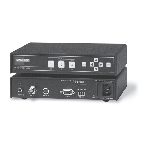
Product Overview Description The IN1402 is a full featured video scaler that combines quad standard video recording, advanced video scaling/line multiplication and a 3-input video switcher into a single product. The IN1402 Video Scaler is recommended for display system applications requiring superb video scaling for composite video and S-video signals. -
Page 5: Compatibility
IN1402, and that the power button is off. Place or install the IN1402 in the desired location. Make sure that the unit is seated on a flat surface or is securely installed in a standard 19” equipment rack. Two IN1402 scalers can be mounted side-by-side using the optional Universal 1U Rack Shelf (Extron part #60-190-01). -
Page 6: Operation
Figure 1 — IN1402 application diagram Operation This section focuses on operating the IN1402 using the front panel controls and commands. All video adjustments, set-up functions, and switching operations can be performed through the front panel or via RS-232 serial controls. RS-232 control information can be found on page 16. -
Page 7: On-Screen Menu
The main menu commands and their functions are Video: Changes input signal video parameters Input: Changes input signal-timing parameters Output: Changes output signal-timing parameters Advanced: Displays advanced options An illustration of the on-screen display menu system is provided on the next page. IN1402 User’s Manual... -
Page 8: In1401 On-Screen Display Menu System
Braces { } H-Position Slashes \ / V-Position Less & Greater < > Signs ! # Sync Format RGBHV-- System Info RGBHV++ Input RGBS Standard RGsB Horizontal Vertical Output Horizontal Vertical Sync Version *Only available on composite video. IN1402 User’s Manual... -
Page 9: Menu Commands
Menu Commands Video Menu The IN1402 allows you to manually adjust the brightness, contrast, color, hue, sharpness, gamma, noise filter, and comb/trap filter settings. To access the video adjustment menu via the front panel control buttons Press the desired INPUT SELECT button. - Page 10 Advanced menu. Gamma: The 30 active gamma correction curves programmed into the IN1402 are used to compensate for the non-linear response of many display devices. Since Gamma, Brightness and Contrast controls interact with each other the following order of adjustments are suggested: Set the brightness and contrast controls to factory default positions.
-
Page 11: Input Menu
4:3 format. The same signals are shown on the right as they would appear on 4:3 and 16:9 display devices with the scaler set to various aspect ratio settings. IN1402 User’s Manual... - Page 12 Example 1 Example 2 IN1402 User’s Manual...
- Page 13 For normal quality video signals, such as from a TV Normal: For good quality video signals, such as from a DVD player Slow: For high quality video signals, such as broadcast video Reset Input resets all input settings to factory default (for the current input only). IN1402 User’s Manual...
-
Page 14: Output Menu
Size adjusts the output horizontal and vertical size. It shrinks the size to a percentage of the output resolution selected. The IN1402 only scales up; choose an output size that will result in an image that is greater than or equal to the input size (don’t forget to save). This setting is useful to manually reduce the height of the output signal when an anamorphic input signal is connected. -
Page 15: Choosing The Optimal Output Resolution
Reset RS-232 resets all RS-232 settings to factory default. Choosing the Optimal Output Resolution Of all the settings on the IN1402, perhaps the most critical adjustment is the output resolution. Every display device has an optimal or native resolution. This will vary depending on the type of display... -
Page 16: Fixed Pixel Displays: Selecting The Optimal Resolution
1280 x 768 Plasma Display 50” / 60” (16:9) (Fujitsu / JVC / Luce / Marantz / NEC / Panasonic NEC 50": Set Sync Format to / RCA / Runco / Samsung / Toshiba) 1365 x 768 RGBHV++ IN1402 User’s Manual... -
Page 17: Advanced Operation
Power-On settings let you adjust key IN1402 settings without using on-screen menus. This may be particularly helpful if the IN1402 has been accidentally set for a mode that is incompatible with the display device, preventing the viewing of the on-screen menus. To execute a Power-On setting, simply press and hold the desired front panel button (indicated in the chart below) while connecting the power cable to the IN1402. -
Page 18: Remote Operation
Baud Rate Selection: The IN1402 has a factory default baud rate of 9600 bps and can communicate at baud rates from 1200 up to 57,600. Baud rates can be selected by selecting Advanced Menu on the Main Menu. -
Page 19: In1402 Serial Commands
IN1402 Transmit Terminal. Multiple IN1402 Transit Lines may not be connected together; otherwise signal contention from multiple units will result. Therefore, “receive” information is only available from one IN1402 in this configuration. Each unit must be set to different delimiters. - Page 20 SYNC4 set output sync to RGsB SYNC? return current output sync * The commands are not case sensitive. ** Default values when factory reset is performed. ♦ Normal and available values depend on the current output mode. IN1402 User’s Manual...
-
Page 21: Troubleshooting
• Solution 2: Make sure the A/C source is live. • Solution 3: Verify that the power switch is turned on for the video source, the IN1402 and the monitor/display device. • Solution 4: Verify the connection to the output display device. Even with no input signal, the IN1402 menu can be displayed. - Page 22 Problem: The desired input aspect ratio cannot be selected. • Solution 1: The IN1402 can only scale up. Increase the output resolution until the desired aspect ratio is available. • Solution 2: Manually decrease the image size by using the output menu.
-
Page 23: Specifications
4.3 cm H x 21.6 cm W x 15.2 cm D (Depth excludes connectors.) Product weight ......2.5 lbs (1.1 kg) Shipping weight ......5 lbs (3 kg) Vibration ........ISTA 1A in carton (International Safe Transit Association) IN1402 User’s Manual... -
Page 24: Part Numbers
MTBF ..........30,000 hours Warranty ........3 years parts and labor All nominal levels are at ±10%. Specifications are subject to change without notice. Part Numbers These items are included with the IN1402. Included Parts Part Numbers IN1402 scaler 60-729-01... - Page 25 Extron’s Warranty Extron Electronics warrants this product against defects in materials and workmanship for a period of two years from the date of purchase. In the event of malfunction during the warranty period attributable directly to faulty workmanship and/or materials, Extron Electronics will, at its option,...
- Page 26 Kyodo Building Anaheim, CA 92805 3821 AH Amersfoort PM Industrial Building 16 Ichibancho The Netherlands Singapore 368363 Chiyoda-ku, Tokyo 102-0082 Japan 714.491.1500 +31.33.453.4040 +65.6383.4400 +81.3.3511.7655 www.extron.com Fax 714.491.1517 Fax +31.33.453.4050 Fax +65.6383.4664 Fax +81.3.3511.7656 © 2005 Extron Electronics. All rights reserved.
Need help?
Do you have a question about the IN1402 and is the answer not in the manual?
Questions and answers