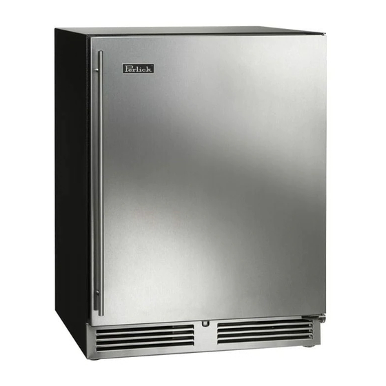
Perlick HA24BB Service Manual

Perlick HA24BB Service Manual

Residential and commercial front venting refrigeration
Hide thumbs Also See for HA24BB:
Table of Contents

Advertisement

Product Series Covered in this Manual:
Residential
HA24BB, HA24RB, HA24WB
HA24FB
HC24BB, HC24RB, HC24RO,
HC24TB, HC24TO, HC24WB
HP15, HK15
HH24
HP24, HK24, HM24 (Med Temp)
HP24, HK24 (Low Temp)
HP24, HK24, HM24 (Dual Zone FRZ/REF)
HP24, HK24, HM24 (Dual Zone, Med Temp)
HP48
HHA24, HPA24
SERVICE MANUAL
Residential and Commercial
Front Venting Refrigeration
HC48
HB24BS, HB24RS, HB24WS
HB24FS
HC24FS, HC24RS, HC24WS
HD24RS, HD24WS
download a pdf copy
Front Venting Commercial
Scan here to
of this manual.
Form No. Z2506

Advertisement

Table of Contents
loading
Need help?

Need help?

Do you have a question about the HA24BB and is the answer not in the manual?

Questions and answers

Summary of Contents for Perlick HA24BB

  • Page 1 SERVICE MANUAL Residential and Commercial Front Venting Refrigeration Product Series Covered in this Manual: Residential Front Venting Commercial HA24BB, HA24RB, HA24WB HC48 HA24FB HB24BS, HB24RS, HB24WS HC24BB, HC24RB, HC24RO, HB24FS HC24TB, HC24TO, HC24WB HC24FS, HC24RS, HC24WS HP15, HK15 HD24RS, HD24WS...
  • Page 2 Residential Refrigeration and Front Venting Commercial Refrigeration Service Manual Table of Contents 1.0 GENERAL INFORMATION ................1-1 Use of Service Manual ..................1-1 Model Families ....................1-1 2.0 SAFETY INFORMATION ................... 2-1 Refrigerant HFC-134a ..................2-1 Potential Problems with HFC-134a ..............2-1 Service Manual Safety Labels ................2-1 3.0 TROUBLESHOOTING GUIDE ................
  • Page 3: Table Of Contents

    Residential Refrigeration and Front Venting Commercial Refrigeration Service Manual 8.0 ELECTRICAL SYSTEM REPAIR INSTRUCTONS..........8-1 Electrical Specifications ................... 8-1 Wiring Diagrams .................... 8-2 Load Operation Modes ..................8-18 Electronic Controller ..................8-26 Factory Set Point .................... 8-27 8.6.1 Dixell Controller: Reset Factory Parameter Settings ........... 8-30 8.6.2 Eliwell Controller: Reset Factory Parameter Settings ..........
  • Page 4 Residential Refrigeration and Front Venting Commercial Refrigeration Service Manual HA24 Low Temperature Cabinets - Evaporator Compartment Service Parts ..10-16 HA24 Medium Temperature Cabinets - Condenser Compartment Service Parts .. 10-17 HA24 Low Temperature Cabinets - Condenser Compartment Service Parts ..10-19 HA24 Cabinets - Door Service Parts ..............
  • Page 5 Residential Refrigeration and Front Venting Commercial Refrigeration Service Manual Table of Figures Figure 1-1. Information Plate ................... 1-1 Figure 7-1. Sealing Compound at Wiring Pass-through – Back ..........7-1 Figure 7-2. Sealing Compound at Wiring Pass-through – Inside .......... 7-2 Figure 7-3.
  • Page 6 Residential Refrigeration and Front Venting Commercial Refrigeration Service Manual Figure 9-3. Hinge Installation ................... 9-2 Figure 9-4. Door Brackets ....................9-2 Figure 9-5. Removing Front Panel ..................9-3 Figure 9-6. Bearing and V-Block ..................9-3 Figure 9-7. Door Hinges ....................9-3 Figure 9-8.
  • Page 7 C0 and temperature ......7-1 Table 8-1. Electrical Specifications ..................8-1 Table 8-2. HA24BB, RB, WB Load Operation Modes ............8-18 Table 8-3. HA24FB Load Operation Modes................ 8-18 Table 8-4. HB24BS, RS, WS Load Operation Modes ............8-18 Table 8-5.
  • Page 8: General Information

    If you have any questions or require additional assistance, contact Perlick Customer Service during regular hours of operation. Model Families This manual contains specific instructions for servicing the Perlick Residential and Front Venting Commercial Series refrigeration products, which include the following families: RESIDENTIAL FRONT VENTING COMMERCIAL Figure 1-1.
  • Page 9: Safety Information

    Service Manual 2.0 Safety Information • Flux must not be used on any brazed joints. Refrigerant HFC-134a Anytime a Perlick Refrigeration System is being All self-contained models covered in this service serviced: manual are manufactured using refrigerant HFC- • It is recommended that the drier be changed 134a.
  • Page 10: Trouble Shooting Guide

    3.0 Trouble Shooting Guide Refrigeration System Use this diagnostic guide to identify issues and to locate applicable instructions within this service manual. This diagnostic guide can be used for any of Perlick’s Residential and Front Venting Commercial Series Re- frigeration Products. ELECTROCUTION HAZARD!!
  • Page 11 Residential Refrigeration and Front Venting Commercial Refrigeration Service Manual PROBLEM CAUSE SOLUTION Probe failure. Refer to Table 8-21 for resistance values. Re- place probe if needed. See Section 8.6.4. Reconnect probe. See Section 8.6.4 . Probe is not connected to the control. Refrigerator is too warm.
  • Page 12 Residential Refrigeration and Front Venting Commercial Refrigeration Service Manual PROBLEM CAUSE SOLUTION Refrigeration/Charge level is too low. Check for leaks, repair, and recharge per Section 7.13 and 7.14 . Water on the floor outside High ambient temperature and high am- Ensure doors close completely.
  • Page 13: Electrical System

    Residential Refrigeration and Front Venting Commercial Refrigeration Service Manual Electrical System PROBLEM CAUSE SOLUTION Compressor is not running. No power to compressor. Check wiring to compressor. Check where power is interrupted between controller and compressor. Check control settings or for bad control. No call for cooling from control.
  • Page 14 Residential Refrigeration and Front Venting Commercial Refrigeration Service Manual PROBLEM CAUSE SOLUTION Replace evaporator fan per Section 7.11 . If Evaporator fan is still not running If no power: restore power, replace. Refer to No power to/from DC inverter/driver Section 1.1 . (12V).
  • Page 15 Residential Refrigeration and Front Venting Commercial Refrigeration Service Manual PROBLEM CAUSE SOLUTION Replace probe per Section 8.6.3 . Eliwell Control: LED Probe 1 HIGH temperature alarm. Controller display is flash- Control ing “AH1” Incorrect control settings. Return to factory settings. See Section 8.6 . Power Incorrectly wired.
  • Page 16 Residential Refrigeration and Front Venting Commercial Refrigeration Service Manual PROBLEM CAUSE SOLUTION Table 8-21 for resistance values. Probe failure. Control failure. Refer to Control not functioning Refer to Table 8-21 for resistance values Dixell Control: LED Probe failure. Controller display is flash- Probe disconnected from control.
  • Page 17 Residential Refrigeration and Front Venting Commercial Refrigeration Service Manual PROBLEM CAUSE SOLUTION Check for leaks, repair, and recharge per Refrigeration/Charge level is too low. Section 7.13 and 7.14 . This is a critically charged system, recharging should only be done when all other options have been thoroughly checked.
  • Page 18 Residential Refrigeration and Front Venting Commercial Refrigeration Service Manual Doors, Drawers and Shelving PROBLEM CAUSE SOLUTION Key won’t come out after Key not in proper position. Rotate key to the proper position and remove. door is locked. Verify proper mounting. Refer to Hinge problems, door Improper door mounting Section 9.2 .
  • Page 19 Residential Refrigeration and Front Venting Commercial Refrigeration Service Manual Beverage Dispensing DIRECT DRAW SYSTEMS PROBLEM CAUSE SOLUTION Temperature too warm Adjust temperature control or call qualified Beer Foaming (should be 36° F) service person Temperature too cold/frozen beer in lines Adjust temperature control or call qualified (should be 36°...
  • Page 20 Always use specified inverter when testing compressor! • The compressors employed within many of Perlick’s cabinets are on the cutting edge of technology for reciprocating hermetic compressors. The compressors are variable speed models developed and man- ufactured by Embraco. Depending on the model of the cabinet, either a VEMY3H, VEMY6H or VEGY7H will be found powering the refrigeration system.
  • Page 21: Normal Operation

    Residential Refrigeration and Front Venting Commercial Refrigeration Service Manual 5.0 Compressor Inverter Operation • Upon initial power to the inverter, the electronic board is checked for problems or malfunctioning components. If a problem is detected, the inverter will not allow power to the compressor and will wait 8 minutes until it will repeat the process to see if it has been corrected.
  • Page 22: Figure 7-1. Sealing Compound At Wiring Pass-Through - Back

    Residential Refrigeration and Front Venting Commercial Refrigeration Service Manual 6.0 Troubleshooting Compressor Inverter 120V applied to the two pin connector on the inverter. If no power, • Ensure the inverter has check where power is interrupted. • If temperature control is calling for cooling, check inverter signal circuit for 120V, typically the red lead.
  • Page 23: Figure 7-2. Sealing Compound At Wiring Pass-Through - Inside

    Residential Refrigeration and Front Venting Commercial Refrigeration Service Manual Figure 7-2. Sealing Compound at Wiring Pass-through – Figure 7-3. Evaporator Condensate Drain Inside Note: Drain tube should be routed through metal bracket and end of tube should be retained by metal STEP 3.
  • Page 24: Table 7-1. System Operating Pressures

    Residential Refrigeration and Front Venting Commercial Refrigeration Service Manual System Operating Pressures Note: To check operating pressures, you must install access valves onto the process tubes. See Section 7.2.1. Table 7-1 represent a range of normal pressures. The measured pressure can vary depending on Values in ambient conditions and at the point at which unit is in the refrigeration cycle.
  • Page 25: Figure 7-4. Process Tubes

    Residential Refrigeration and Front Venting Commercial Refrigeration Service Manual 7.2.1 Process Tubes and Access Valve Refrigerant system is hermetically sealed. Use access tubes to charge unit and check pressure. Shelf Lock Note: Access valves (saddle valves) are not provided and may vary. Access valves should never be left on the equipment permanently as they tend to leak over time.
  • Page 26: Figure 7-8. Evaporator Fan Panel Screw Locations

    Residential Refrigeration and Front Venting Commercial Refrigeration Service Manual STEP 2. De-Ice Blocked Evaporator Coil Remove Evaporator Fan panel by removing 2 (or 4) Phillips head screws from around the evaporator fan. See Figure 7-8. Use towels to absorb water to avoid damage to ma- chine compartment or surrounding flooring.
  • Page 27 Standard-In at the bottom through louvers, out at HP24RS Standard the top through fan. HP24TO Standard Evaporator Airflow HP24TS Standard Model Direction HP24WO Standard HP24WS Standard HA24BB Standard HPA24BO Standard HA24FB Standard HPA24RO Standard HA24RB Standard HPA24WO Standard HA24WB Standard HP48WO-S...
  • Page 28: Figure 7-11. Check For Obstructions

    Main electrical power has been dis- eration system failure. connected. The unit must be protected from precipitation. Perlick’s warranty does not cover cleaning of con- Do not subject to direct solar load. denser. Under extreme temperature and/or relative humidity...
  • Page 29: Table 7-2. Compressor Data

    Residential Refrigeration and Front Venting Commercial Refrigeration Service Manual Compressors Table 7-2. Compressor Data START STARTING MOTOR CAPACITOR WINDING WINDING LOCKED DEVICE PROTECTION (Run/Start) ROTOR (uF/VAC Minimum) RESISTANCE RESISTANCE COMPRESSOR MOTOR AMPERAGE Ω AT 77°F Ω AT 77°F MODEL TYPE (LRA) (+/-8%) (+/-8%)
  • Page 30: Figure 7-14. Condenser Fan Mounting Hardware

    Power Leads Figure 7-14. Condenser Fan Mounting Hardware STEP 4. Install new fan motor using 2 Phillips head screws and connect power leads. Use only original Perlick OEM parts. STEP 5. Install equipment compartment rear cover. Return to Table of Contents...
  • Page 31 Evaporator fan motor can now be replaced. Evapo- components. Additionally, look for oil that rator fan motor should only be replaced with Perlick has leaked from the system to determine the OEM parts.
  • Page 32 Residential Refrigeration and Front Venting Commercial Refrigeration Service Manual Once charge level has been set, avoid installing gauges as part of regular service. System should be kept sealed. Do not “top off” or add refrigerant to an unknown existing charge. Completely recover existing refrigerant in accor- dance with EPA regulations and thoroughly evacu- ate the system.
  • Page 33: Table 7-3. C0

    Residential Refrigeration and Front Venting Commercial Refrigeration Service Manual used to maintain proper beer line temperature are Beverage Dispensing working properly. The troubleshooting steps that follow are Perfectly poured draught beer is the result of organized by the type of draught beer system and proper temperature, gas pressure, mixture, and how the systems are cooled, using air.
  • Page 34 Carbonation level not known. Tools required STEP 5. Set the regulator pressure to 5 psi. Perlick Cleaning Kit (Part No. 63797): STEP 6. Tap a fresh keg. Make sure the keg has been in the cooler long enough to be at the cooler tem- perature.
  • Page 35 STEP 3. STEP 13. If tapping device contains a check ball, insert check ball lifter into the bottom of the coupler (Perlick Rinse out cleaning pump jar with fresh water Low Profile Coupler does not contain a check ball). STEP 14.
  • Page 36: Figure 7-15. Dual Zone F-R Gen 3 Refrigeration System Diagram

    Residential Refrigeration and Front Venting Commercial Refrigeration Service Manual Refrigeration System Diagrams Figure 7-15. Dual Zone F-R Gen 3 Refrigeration System Diagram Dual Zone: Freezer/Refrigerator ITEM ITEM DESCRIPTION DESCRIPTION NUMBER NUMBER Compressor Evaporator Fan (Lower) Condenser Temperature Control Condenser Fan Liquid Line Solenoid (Upper) Drier Capillary Tube (Upper)
  • Page 37: Figure 7-16. Dual Zone Med Temp Gen 3 Refrigeration System Diagram

    Residential Refrigeration and Front Venting Commercial Refrigeration Service Manual Figure 7-16. Dual Zone Med Temp Gen 3 Refrigeration System Diagram Dual Zone: Refrigerator/Wine, Wine/Wine ITEM ITEM DESCRIPTION DESCRIPTION NUMBER NUMBER Compressor Evaporator Fan (Lower) Condenser Temperature Control Condenser Fan Liquid Line Solenoid (Upper) Drier Capillary Tube (Upper) Heat Exchanger (Upper)
  • Page 38 Residential Refrigeration and Front Venting Commercial Refrigeration Service Manual Figure 7-17. Freezer/Commercial Chiller Refrigeration System Diagram Freezer/Commercial Chiller ITEM ITEM DESCRIPTION DESCRIPTION NUMBER NUMBER Compressor Capillary Tube Condenser Heat Exchanger Condenser Fan Evaporator Drier Evaporator Fan Hot - Gas Bypass Valve Temperature Control Return to Table of Contents...
  • Page 39: Figure 7-18. Med Temp Refrigeration System Diagram

    Residential Refrigeration and Front Venting Commercial Refrigeration Service Manual Figure 7-18. Med Temp Refrigeration System Diagram Refrigerator/Beverage Center/Wine Res/Beer Dispenser ITEM ITEM DESCRIPTION DESCRIPTION NUMBER NUMBER Compressor Capillary Tube Condenser Heat Exchanger Condenser Fan Evaporator Drier Evaporator Fan Temperature Control Return to Table of Contents Refrigeration System Repair Instructions...
  • Page 40: Table 8-1. Electrical Specifications

    Electrical Specifications Verify adequate power is supplied. Table 8-1. Electrical Specifications Model Number Running Electrical Supply Electrical Connection Load Amps HA24BB, RB, WB 115V/60Hz/1Ph Cord Connected 5-15P HA24FB HB24BS, RS, WS HB24FS HC24BB, RB, RO, TB, TO, WB HC24RS, WS...
  • Page 41: Figure 8-1. Hc24Rs & Hc24Ws Wiring Diagram

    Residential Refrigeration and Front Venting Commercial Refrigeration Service Manual Wiring Diagrams Figure 8-1. HC24RS & HC24WS Wiring Diagram Return to Table of Contents Electrical System Repair Instructions Page 8-2...
  • Page 42: Figure 8-2. Hc24Fs Wiring Diagram

    Residential Refrigeration and Front Venting Commercial Refrigeration Service Manual Figure 8-2. HC24FS Wiring Diagram Return to Table of Contents Electrical System Repair Instructions Page 8-3...
  • Page 43: Figure 8-3. Hp48 Signature Series Wiring Diagram

    Residential Refrigeration and Front Venting Commercial Refrigeration Service Manual Figure 8-3. HP48 Signature Series Wiring Diagram Return to Table of Contents Electrical System Repair Instructions Page 8-4...
  • Page 44: Figure 8-4. Hp24 Signature Series Wiring Diagram

    Residential Refrigeration and Front Venting Commercial Refrigeration Service Manual Figure 8-4. HP24 Signature Series Wiring Diagram Return to Table of Contents Electrical System Repair Instructions Page 8-5...
  • Page 45: Figure 8-5. Hp Freezers Wiring Diagram

    Residential Refrigeration and Front Venting Commercial Refrigeration Service Manual Figure 8-5. HP Freezers Wiring Diagram Return to Table of Contents Electrical System Repair Instructions Page 8-6...
  • Page 46: Figure 8-6. Ha Freezers Wiring Diagram

    Residential Refrigeration and Front Venting Commercial Refrigeration Service Manual Figure 8-6. HA Freezers Wiring Diagram Return to Table of Contents Electrical System Repair Instructions Page 8-7...
  • Page 47: Figure 8-7. Hp15 Signature Series Wiring Diagram

    Residential Refrigeration and Front Venting Commercial Refrigeration Service Manual Figure 8-7. HP15 Signature Series Wiring Diagram Return to Table of Contents Electrical System Repair Instructions Page 8-8...
  • Page 48: Figure 8-8. Hc & Hh Wiring Diagram

    Residential Refrigeration and Front Venting Commercial Refrigeration Service Manual Figure 8-8. HC & HH Wiring Diagram Return to Table of Contents Electrical System Repair Instructions Page 8-9...
  • Page 49: Figure 8-9. Ha Wiring Diagram

    Residential Refrigeration and Front Venting Commercial Refrigeration Service Manual Figure 8-9. HA Wiring Diagram Return to Table of Contents Electrical System Repair Instructions Page 8-10...
  • Page 50: Figure 8-10. Hb24Bs, Hb24Rs & Hb24Ws Wiring Diagram

    Residential Refrigeration and Front Venting Commercial Refrigeration Service Manual Figure 8-10. HB24BS, HB24RS & HB24WS Wiring Diagram Return to Table of Contents Electrical System Repair Instructions Page 8-11...
  • Page 51: Figure 8-11. Hb24Fb & Hb24Fs Ada Series Wiring Diagram

    Residential Refrigeration and Front Venting Commercial Refrigeration Service Manual Figure 8-11. HB24FB & HB24FS ADA Series Wiring Diagram Return to Table of Contents Electrical System Repair Instructions Page 8-12...
  • Page 52: Figure 8-12. Hpa & Hha Wiring Diagram

    Residential Refrigeration and Front Venting Commercial Refrigeration Service Manual Figure 8-12. HPA & HHA Wiring Diagram Return to Table of Contents Electrical System Repair Instructions Page 8-13...
  • Page 53: Figure 8-13. Hc Wiring Diagram

    Residential Refrigeration and Front Venting Commercial Refrigeration Service Manual Figure 8-13. HC Wiring Diagram Return to Table of Contents Electrical System Repair Instructions Page 8-14...
  • Page 54: Figure 8-14. Hc48Rs, Hc48Ws, Hc48Rw & Hc48Ww Wiring Diagram

    Residential Refrigeration and Front Venting Commercial Refrigeration Service Manual Figure 8-14. HC48RS, HC48WS, HC48RW & HC48WW Wiring Diagram Return to Table of Contents Electrical System Repair Instructions Page 8-15...
  • Page 55: Figure 8-15. Hp24Zs/Zo Wiring Diagram

    Residential Refrigeration and Front Venting Commercial Refrigeration Service Manual Figure 8-15. HP24ZS/ZO Wiring Diagram Electrical System Repair Instructions Page 8-16 Return to Table of Contents...
  • Page 56: Figure 8-16. Hp24Cs/Co/Ds/Do Wiring Diagram

    Residential Refrigeration and Front Venting Commercial Refrigeration Service Manual Figure 8-16. HP24CS/CO/DS/DO Wiring Diagram Return to Table of Contents Electrical System Repair Instructions Page 8-17...
  • Page 57: Table 8-2. Ha24Bb, Rb, Wb Load Operation Modes

    Residential Refrigeration and Front Venting Commercial Refrigeration Service Manual Load Operation Modes Table 8-2. HA24BB, RB, WB Load Operation Modes Models: HA24BB, RB, WB Temperature Control: Electro-mechanical Defrost Style: Off cycle defrost Cabinet Lighting: Lights are controlled through a manual on/off switch as well as through the door switch.
  • Page 58: Table 8-5. Hb24Fs Load Operation Modes

    Residential Refrigeration and Front Venting Commercial Refrigeration Service Manual Table 8-5. HB24FS Load Operation Modes Models: HB24FS Temperature Control: Electro-mechanical Defrost Style: Hot Gas Defrost Cabinet Lighting: Lights are controlled through a manual on/off switch as well as through the door switch. LOAD COOLING MODE OFF MODE...
  • Page 59: Table 8-8. Hc24Rs, Ws Load Operation Modes

    Residential Refrigeration and Front Venting Commercial Refrigeration Service Manual Table 8-8. HC24RS, WS Load Operation Modes Models: HC24RS, WS Temperature Control: Electro-mechanical Defrost Style: Off cycle defrost Cabinet Lighting: Lights are controlled through a manual on/off switch as well as through the door switch.
  • Page 60: Table 8-11. Hp15Bo, Bs, Ro, Rs, To, Ts, Hk15Bo, Ro, To Load Operation Modes

    Residential Refrigeration and Front Venting Commercial Refrigeration Service Manual Table 8-11. HP15BO, BS, RO, RS, TO, TS, HK15BO, RO, TO Load Operation Modes Models: HP15BO, BS, RO, RS, TO, TS, HK15BO, RO, TO Electronic Control: Dixell (XR60CX) Defrost Style: Programmed Defrost (12 hours--15 minutes) Cabinet Lighting: Lights are controlled through a manual on/off switch as well as through the door switch.
  • Page 61: Table 8-13. Hp24Bo, Bs, Ro, Rs, To, Ts, Hk24Bo, Ro, To, Hm24Ro, To Load Operation

    Residential Refrigeration and Front Venting Commercial Refrigeration Service Manual Table 8-13. HP24BO, BS, RO, RS, TO, TS, HK24BO, RO, TO, HM24RO, TO Load Operation Modes Models: HP24BO, BS, RO, RS, TO, TS, HK24BO, RO, TO, HM24RO, TO Electronic Control: Dixell (XR60CX) Defrost Style: Programmed Defrost (12 hours--15 minutes) Cabinet Lighting:...
  • Page 62: Table 8-16. Hp24Co, Cs, Do, Ds, Hk24Co, Do, Hm24Co Load Operation Modes

    Residential Refrigeration and Front Venting Commercial Refrigeration Service Manual Table 8-16. HP24CO, CS, DO, DS, HK24CO, DO, HM24CO Load Operation Modes Models: HP24CO, CS, DO, DS, HK24CO, DO, HM24CO Electronic Control: Dixell (XR72CX) Defrost Style: Programmed Cycle Cabinet Lighting: Lights are controlled through a manual on/off switch as well as through the door switch.
  • Page 63: Table 8-17. Hp24Zo, Zs, Hk24Zo, Hm24Zo Load Operation Modes

    Residential Refrigeration and Front Venting Commercial Refrigeration Service Manual Table 8-17. HP24ZO, ZS, HK24ZO, HM24ZO Load Operation Modes Models: HP24ZO, ZS, HK24ZO, HM24ZO Electronic Control: Dixell (XR72CX) Defrost Style: Hot Gas Defrost Cabinet Lighting: Lights are controlled through a manual on/off switch as well as through the door switch.
  • Page 64: Table 8-18. Hc48Rs, Rw, Ws, Ww Load Operation Modes

    Residential Refrigeration and Front Venting Commercial Refrigeration Service Manual Table 8-18. HC48RS, RW, WS, WW Load Operation Modes Models: HC48RS, RW, WS, WW Electronic Control: Dixell (XR60CX) -- First Compartment (All models) Electronic Control: Dixell (XR20CX) -- Second Compartment (RW, WW models) Defrost Style: Programmed Defrost (12 hours-30 minutes) Cabinet Lighting:...
  • Page 65: Electronic Controller

    Residential Refrigeration and Front Venting Commercial Refrigeration Service Manual Electronic Controller Dixell Controller Note: The digital readout is monitoring true air temperature, not product temperature. Most electronic controls may have an offset pro- grammed into the control and has a display delay programmed into the control (please see factory program tables for proper set- tings).
  • Page 66: Table 8-20. Factory Temperature Settings

    Type Offset Delay Display Defrost Type Timing 33-42 Off Cycle HA24RB, Electro- Mechanical HB24RS, HC24RS, HD24RS 33-46 Off Cycle HA24BB, Electro-Mechanical HB24BS 45-65 Off Cycle HA24WB, Electro-Mechanical HB24WS, HC24WS, HD24WS Digital Hot Gas 10 Hrs 3 Mins HA24FB, -10 - +10...
  • Page 67: Hk24Zo

    Residential Refrigeration and Front Venting Commercial Refrigeration Service Manual Temp Set Point Set Point Hysteresis Fan Delay Control Models Range (F) (Air Temp) Offset Delay Display Defrost Type Timing Post Defrost Type Digital 30-42 Programmed 12 Hrs HP15RO, Temp 15 Mins HP15RS, HP15TO, HP15TS,...
  • Page 68: Hp48Wo-S, Hp48Ww-S

    Residential Refrigeration and Front Venting Commercial Refrigeration Service Manual Temp Set Point Set Point Hysteresis Fan Delay Control Models Range (F) (Air Temp) Offset Delay Display Defrost Type Timing Post Defrost Type Digital 40-68 HC48RW, Temp HC48WW, 2nd Compartment Digital 40-68 Programmed 12 Hrs...
  • Page 69: Remove Evaporator Fan Panel

    Residential Refrigeration and Front Venting Commercial Refrigeration Service Manual Power 8.6.1 Dixell Controller: Reset Factory Parameter Leads Settings Contact Perlick. Zip Tie 8.6.2 Eliwell Controller: Reset Factory Parameter Settings Contact Perlick. 8.6.3 Replacing Control Module Tools required STEP 4. Reverse Steps 1 – 4 to replace control module.
  • Page 70 Residential Refrigeration and Front Venting Commercial Refrigeration Service Manual STEP 4. Apply even pressure to plastic retainers to release teeth to disengage digital control module. STEP 3. Dixell: Remove 2 black connectors and 1 green probe connector. Note: Remember correct orientation of the connectors to re-connect to new controller.
  • Page 71: Figure 8-17. Temperature Probe

    Residential Refrigeration and Front Venting Commercial Refrigeration Service Manual STEP 5. Reverse this instruction to connect the replacement controller. 8.6.4 Temperature Probe Each refrigerated zone has one 10K ohm NTC probe, which senses compartment temperature. Sensing probe is located behind the control cradle or next to the evaporator fan behind the cover panel.
  • Page 72: Figure 8-18. Interior Led Light

    Residential Refrigeration and Front Venting Commercial Refrigeration Service Manual LED Lighting Replace DC Driver/Inverter 8.7.1 Replace LED Light Strip STEP 1. DC Drivers are located in control tray for LED lights and behind front grille for DC evaporator and con- ELECTROCUTION HAZARD!! Never attempt to denser fan motors.
  • Page 73: Step

    Residential Refrigeration and Front Venting Commercial Refrigeration Service Manual Mullion Heater Hook-Up 8.10 STEP 1. STEP 3. The rear panel and the front bottom toe kick grill The wires can be pushed over the compressor need to be removed. If the unit is installed, then it from the front or pulled from the rear by locating needs to be pulled out.
  • Page 74: Step

    Residential Refrigeration and Front Venting Commercial Refrigeration Service Manual STEP 4. The black mullion heater wire with the red female push connector will connect to a red male push on connector that has a white cap. It is also a black wire. This male connector can be a little tricky to locate.
  • Page 75: Figure 9-1. Door Removal

    Figure 9-1. Door Removal 67439R Right Hinging 67439L Left Hinging STEP 2. Pull door to the side and then lower the door. Tools required Perlick Hinge Kit Return to Table of Contents Service Instructions - Door, Drawers and Shelving Page 9-1...
  • Page 76: Figure 9-2. Hinge Removal

    Residential Refrigeration and Front Venting Commercial Refrigeration Service Manual STEP 3. STEP 5. Remove top and bottom hinge brackets. Retain Using screws removed in step 3, install top and screws for later use. See Figure 9-2. bottom hinge brackets from kit. See Figure 9-3. Figure 9-3.
  • Page 77: Step

    Residential Refrigeration and Front Venting Commercial Refrigeration Service Manual STEP 7. STEP 9. Remove front panel from door assembly by re- Insert V-block into door bottom hinge bracket moving inner mounting screws (4 per side) from and attach with e-clip. See Figure 9-6. Note the perimeter of door assembly.
  • Page 78: Step

    Residential Refrigeration and Front Venting Commercial Refrigeration Service Manual STEP 11. STEP 13. Place lower V-block into lower cabinet hinge with Insert and tighten lower hinge pin to complete notch parallel to cabinet. See Figure 9-8. assembly. Do not overtighten lower hinge pin as threads engage into lower plastic v-block.
  • Page 79: Step

    Residential Refrigeration and Front Venting Commercial Refrigeration Service Manual STEP 3. Reposition each bracket separately. Grasp middle of bracket, pull front end up and out, and then forward to remove. STEP 4. Place brackets at desired location and reinstall shelf(s). Ensure shelf is locked into slides by STEP 4.
  • Page 80: Step

    Residential Refrigeration and Front Venting Commercial Refrigeration Service Manual NOTE: There are two screws on each end STEP 3. behind the mullion. To replace, start at one corner and press firmly to seat the gasket dart in the channel of the door/ drawer frame.
  • Page 81: Step

    Residential Refrigeration and Front Venting Commercial Refrigeration Service Manual Replace Door Handle Tools required 3/8” STEP 3. Remove door gasket. See Section 9.5. STEP 4. STEP 7. Remove 16 screws underneath door gasket that Reverse these steps to replace door handle, hold door overlay panel to door frame.
  • Page 82: Step

    Residential Refrigeration and Front Venting Commercial Refrigeration Service Manual Custom Overlay Panels STEP 3. Tools Required In some cases, the dart on the gasket may rip. If this happens, replace with a new gasket. 9.9.1 Overlay Panel Installation STEP 1. Wood overlay install ready.
  • Page 83: Step

    Residential Refrigeration and Front Venting Commercial Refrigeration Service Manual STEP 7. STEP 5. Make sure the overlay panel is aligned properly (16) #10 x ¾” Wood screws. with the door. NOTE: Choose fasteners for proper thickness of overlay material. STEP 8. STEP 6.
  • Page 84: Step

    Residential Refrigeration and Front Venting Commercial Refrigeration Service Manual STEP 10. STEP 12. Verify that the gasket is fully seated into the door Completed. frame when completed. STEP 11. After installation of the overlay panel is com- pleted, verify that the gasket is completely seal- ing around the cabinet frame.
  • Page 85: Replacement Parts

    Residential Refrigeration and Front Venting Commercial Refrigeration Service Manual 10.0 Replacement Parts For parts ordering call (844) 411-8050. HP24 Medium Temperature Cabinets - Evaporator Compartment Service Parts ITEM DESCRIPTION NUMBER Digital Controller (Must Specify Temp. Zone) 3 Position Switch Blue & White Led Light Board (Not Shown) LED Light Cover (Not Shown) Temperature Probe LED Driver...
  • Page 86: Hp24 Low Temperature Cabinets - Evaporator Compartment Service Parts

    Residential Refrigeration and Front Venting Commercial Refrigeration Service Manual ITEM DESCRIPTION NUMBER Main Control Box Wire Harness (Not Shown) DC Fan Motor Wire Harness (Not Shown) LED Driver to LED Light Board Wire Harness (Not Shown) HP24 Low Temperature Cabinets - Evaporator Compartment Service Parts ITEM DESCRIPTION NUMBER...
  • Page 87: Hp24 Medium Temperature Cabinets - Condenser Compartment Service Parts

    Residential Refrigeration and Front Venting Commercial Refrigeration Service Manual ITEM DESCRIPTION NUMBER DC Fan Motor Wire Harness (Not Shown) LED Driver to LED Light Board Wire Harness (Not Shown) HP24 Medium Temperature Cabinets - Condenser Compartment Service Parts ITEM DESCRIPTION NUMBER Compressor, VEMY3H W/O Inverter Inverter, Compressor, 115V...
  • Page 88: Hp24 Low Temperature Cabinets - Condenser Compartment Service Parts

    Residential Refrigeration and Front Venting Commercial Refrigeration Service Manual ITEM DESCRIPTION NUMBER Power Cord (Not Shown) Condenser Fan Motor 24VDC Fan Driver Machine Compartment Wire Harness (Not Shown) Door Switch to Led Light Wire Harness (Not Shown) HP24 Low Temperature Cabinets - Condenser Compartment Service Parts ITEM DESCRIPTION NUMBER...
  • Page 89: Condenser Fan

    Residential Refrigeration and Front Venting Commercial Refrigeration Service Manual ITEM DESCRIPTION NUMBER Grommet 3/8” Washer (Not Shown) Compressor Electrical Parts Kit TSD Assembly Run Capacitor, 12uf Bale Strap (Not Shown) Condenser Fin Coil Door Plunger Switch Single Pole Rocker Switch Replacement Grill Grill Latch Strikes...
  • Page 90: Hp24 Cabinets – Door Service Parts

    Residential Refrigeration and Front Venting Commercial Refrigeration Service Manual HP24 Cabinets – Door Service Parts ITEM DESCRIPTION NUMBER Replacement Door (Must Specify Style) Door Overlay Panel Magnetic Gasket Stainless Steel Handle, Door Plunger Pusher Left Hinge Kit Right Hinge Kit (Not Shown) Left Lock Kit, for Right Hinged Door Right Lock Kit, for Left Hinged Door Return to...
  • Page 91: Hp24 Cabinets - Shelving Service Parts

    Residential Refrigeration and Front Venting Commercial Refrigeration Service Manual HP24 Cabinets - Shelving Service Parts ITEM DESCRIPTION NUMBER Replacement Drawer (Must Specify Style) Replacement Drawer Overlay Magnetic Gasket, for Drawer Foamed Drawer Front, without Overlay Replacement Mullion (Must Specify) Drawer Slide Set Lock Kit, for Drawers Return to Table of Contents...
  • Page 92: Hp24 Cabinets - Drawer Service Parts

    Residential Refrigeration and Front Venting Commercial Refrigeration Service Manual HP24 Cabinets - Drawer Service Parts ITEM DESCRIPTION NUMBER Replacement Shelf (Must Specify Style) Stainless Steel Face Plate, for Wine Shelf Wood Face Plate, for Wine Shelf Floor Rack Return to Table of Contents Replacement Parts Page 10-8...
  • Page 93: Hp15 Cabinets – Evaporator Compartment Service Parts

    Residential Refrigeration and Front Venting Commercial Refrigeration Service Manual HP15 Cabinets – Evaporator Compartment Service Parts ITEM DESCRIPTION NUMBER Digital Controller (Must Specify Temp. Zone) 3 Position Switch Blue & White LED Light Board (Not Shown) Led Light Cover (Not Shown) Led Driver Temperature Probe Temperature Probe Clip...
  • Page 94: Hp15 Cabinets - Condenser Compartment Service Parts

    Residential Refrigeration and Front Venting Commercial Refrigeration Service Manual HP15 Cabinets - Condenser Compartment Service Parts ITEM DESCRIPTION NUMBER Replacement Compressor Kit Compressor, EM20 TSD Assembly Run Capacitor, 5uf Bale Strap (Not Shown) Drier, (2) 1/4” I.D. Inlets & 1/8” I.D. Outlet (Not Shown) 1/4”...
  • Page 95 Residential Refrigeration and Front Venting Commercial Refrigeration Service Manual ITEM DESCRIPTION NUMBER Blue & White Led Light Board (Not Shown) LED Light Cover (Not Shown) LED Driver Temperature Probe Grill Latch Strikes Latches Adhesive Poly. Bumpers Temperature Probe Clip Evaporator Fan Motor Evaporator Fin Coil L&S Line (Not Shown) Main Control Box Wire Harness (Not Shown)
  • Page 96: Hp15 Cabinets - Door Service Parts

    Residential Refrigeration and Front Venting Commercial Refrigeration Service Manual HP15 Cabinets - Door Service Parts ITEM DESCRIPTION NUMBER Replacement Door (Must Specify Style) Door Overlay Panel Magnetic Gasket Stainless Steel Handle, Door Plunger Pusher Left Hinge Kit Right Hinge Kit (Not Shown) Left Lock Kit, for Right Hinged Door Right Lock Kit, for Left Hinged Door Return to...
  • Page 97: Hp15 Cabinets - Shelving Service Parts

    Residential Refrigeration and Front Venting Commercial Refrigeration Service Manual HP15 Cabinets - Shelving Service Parts ITEM DESCRIPTION NUMBER Replacement Shelf (Must Specify Style) Stainless Steel Face Plate, for Wine Shelf Wood Face Plate, for Wine Shelf Floor Rack Return to Table of Contents Replacement Parts Page 10-13...
  • Page 98: Hp15 Cabinets - Drawer Service Parts

    Residential Refrigeration and Front Venting Commercial Refrigeration Service Manual HP15 Cabinets - Drawer Service Parts ITEM DESCRIPTION NUMBER Replacement Drawer (Must Specify Style) Replacement Drawer Overlay Magnetic Gasket, for Drawer Foamed Drawer Front, without Overlay Replacement Mullion (Must Specify) Drawer Slide Set Lock Kit, for Drawers Return to Table of Contents...
  • Page 99: Ha24 Medium Temperature Cabinets - Evaporator Compartment Service Parts

    Residential Refrigeration and Front Venting Commercial Refrigeration Service Manual HA24 Medium Temperature Cabinets - Evaporator Compartment Service Parts ITEM DESCRIPTION NUMBER Refrigerator Temperature Control Beverage Center Temperature Control Wine Temperature Control Single Pole Rocker Switch Light Housing Assembly Replacement Light Bulb (Not Shown) Evaporator Fan Motor Evaporator Fin Coil L&S Line (Not Shown)
  • Page 100: Ha24 Low Temperature Cabinets - Evaporator Compartment Service Parts

    Residential Refrigeration and Front Venting Commercial Refrigeration Service Manual HA24 Low Temperature Cabinets - Evaporator Compartment Service Parts ITEM DESCRIPTION NUMBER Digital Controller (Must Specify Temp. Zone) Single Pole Rocker Switch Light Housing Assembly Replacement Light Bulb Evaporator Fan Motor Evaporator Fin Coil L&S Line (Not Shown) Main Control Box Wire Harness (Not Shown)
  • Page 101: Ha24 Medium Temperature Cabinets - Condenser Compartment Service Parts

    Residential Refrigeration and Front Venting Commercial Refrigeration Service Manual HA24 Medium Temperature Cabinets - Condenser Compartment Service Parts ITEM DESCRIPTION NUMBER Replacement Compressor Kit Compressor, EM20 TSD Assembly Run Capacitor, 5uf Bale Strap (Not Shown) Drier, (2) 1/4” I.D. Inlets & 1/8” I.D. Outlet (Not Shown) 1/4”...
  • Page 102: Condenser

    Residential Refrigeration and Front Venting Commercial Refrigeration Service Manual ITEM DESCRIPTION NUMBER Replacement Grill Grill Latch Strikes Latches Adhesive Poly. Bumpers Grill Latch Leveler Leg Rear Cover Plate Drier, 1/4” X 1/8” Inlets (Not Shown) Power Cord (Not Shown) Condenser Fan Motor 24VDC Fan Driver Machine Compartment Wire Harness (Not Shown) Return to...
  • Page 103: Ha24 Low Temperature Cabinets - Condenser Compartment Service Parts

    Residential Refrigeration and Front Venting Commercial Refrigeration Service Manual HA24 Low Temperature Cabinets - Condenser Compartment Service Parts ITEM DESCRIPTION NUMBER Replacement Compressor Kit Compressor, EM20 TSD Assembly Run Capacitor, 12uf Bale Strap (Not Shown) Drier, (2) 1/4” I.D. Inlets & 1/8” I.D. Outlet (Not Shown) 1/4”...
  • Page 104: Condenser Fan

    Residential Refrigeration and Front Venting Commercial Refrigeration Service Manual ITEM DESCRIPTION NUMBER Run Capacitor, 12uf Bale Strap (Not Shown) Condenser Fin Coil Door Plunger Switch Solenoid Valve (Not Shown) Replacement Grill Grill Latch Strikes Latches Adhesive Poly. Bumpers Grill Latch Leveler Leg Rear Cover Plate Drier, 1/4”...
  • Page 105: Ha24 Cabinets - Door Service Parts

    Residential Refrigeration and Front Venting Commercial Refrigeration Service Manual HA24 Cabinets - Door Service Parts ITEM DESCRIPTION NUMBER Replacement Door (Must Specify Style) Door Overlay Panel Magnetic Gasket Stainless Steel Handle, Door Plunger Pusher Left Hinge Kit Right Hinge Kit (Not Shown) Left Lock Kit, for Right Hinged Door Right Lock Kit, for Left Hinged Door Return to...
  • Page 106: Ha24 Cabinets - Shelves Service Parts

    Residential Refrigeration and Front Venting Commercial Refrigeration Service Manual HA24 Cabinets - Shelves Service Parts ITEM DESCRIPTION NUMBER Replacement Shelf (Must Specify Style) Stainless Steel Face Plate, for Wine Shelf Wood Face Plate, for Wine Shelf Floor Rack Return to Table of Contents Replacement Parts Page 10-22...
  • Page 107: Ha24 Cabinets - Drawers Service Parts

    Residential Refrigeration and Front Venting Commercial Refrigeration Service Manual HA24 Cabinets - Drawers Service Parts ITEM DESCRIPTION NUMBER Replacement Drawer (Must Specify Style) Replacement Drawer Overlay Magnetic Gasket, for Drawer Foamed Drawer Front, without Overlay Replacement Mullion (Must Specify) Drawer Slide Set Lock Kit, for Drawers Return to Table of Contents...
  • Page 108: Hh24 Cabinets - Evaporator Compartment Service Parts

    Residential Refrigeration and Front Venting Commercial Refrigeration Service Manual HH24 Cabinets - Evaporator Compartment Service Parts ITEM DESCRIPTION NUMBER Digital Controller (Must Specify Temp. Zone) Single Pole Rocker Switch Light Housing Assembly Replacement Light Bulb Evaporator Fan Motor Evaporator Fin Coil L&S Line (Not Shown) Control Cradle Light Wire Harness (Not Shown) DC Fan Motor Wire Harness (Not Shown)
  • Page 109: Hh24 Cabinets - Condenser Compartment Service Parts

    Residential Refrigeration and Front Venting Commercial Refrigeration Service Manual HH24 Cabinets - Condenser Compartment Service Parts ITEM DESCRIPTION NUMBER Replacement Compressor Kit Compressor, EM20 TSD Assembly Run Capacitor, 5uf Bale Strap (Not Shown) Drier, (2) 1/4” I.D. Inlets & 1/8” I.D. Outlet (Not Shown) 1/4”...
  • Page 110 Residential Refrigeration and Front Venting Commercial Refrigeration Service Manual ITEM DESCRIPTION NUMBER Replacement Grill Grill Latch Strikes Latches Adhesive Poly. Bumpers Grill Latch Leveler Leg Rear Cover Plate Drier, 1/4” X 1/8” Inlets (Not Shown) Power Cord (Not Shown) Condenser Fan Motor 24VDC Fan Driver Machine Compartment Wire Harness (Not Shown) Return to...
  • Page 111: Hh24 Cabinets - Door Service Parts

    Residential Refrigeration and Front Venting Commercial Refrigeration Service Manual HH24 Cabinets - Door Service Parts ITEM DESCRIPTION NUMBER Replacement Door (Must Specify Style) Door Overlay Panel Magnetic Gasket Stainless Steel Handle, Door Plunger Pusher Left Hinge Kit Right Hinge Kit (Not Shown) Left Lock Kit, for Right Hinged Door Right Lock Kit, for Left Hinged Door Return to...
  • Page 112: Hh24 Cabinets - Shelving Service Parts

    Residential Refrigeration and Front Venting Commercial Refrigeration Service Manual HH24 Cabinets - Shelving Service Parts ITEM DESCRIPTION NUMBER Replacement Shelf (Must Specify Style) Stainless Steel Face Plate, for Wine Shelf Wood Face Plate, for Wine Shelf Floor Rack Return to Table of Contents Replacement Parts Page 10-28...
  • Page 113: Compartment Service Parts

    Residential Refrigeration and Front Venting Commercial Refrigeration Service Manual HC24BB, HC24RB, HC24WB, HC24RO, HC24TB & HC24TO Cabinets - Evaporator Compartment Service Parts ITEM DESCRIPTION NUMBER Digital Controller (Must Specify Temp. Zone) Single Pole Rocker Switch Light Housing Assembly Replacement Light Bulb Evaporator Fan Motor Evaporator Fin Coil L&S Line (Not Shown)
  • Page 114: Compartment Service Parts

    Residential Refrigeration and Front Venting Commercial Refrigeration Service Manual HC24BB, HC24RB, HC24WB, HC24RO, HC24TB & HC24TO Cabinets - Condenser Compartment Service Parts ITEM DESCRIPTION NUMBER Replacement Compressor Kit Compressor, EM20 TSD Assembly Run Capacitor, 5uf Bale Strap (Not Shown) Drier, (2) 1/4” I.D. Inlets & 1/8” I.D. Outlet (Not Shown) 1/4”...
  • Page 115 Residential Refrigeration and Front Venting Commercial Refrigeration Service Manual ITEM DESCRIPTION NUMBER TSD Assembly Run Capacitor, 5uf Bale Strap (Not Shown) Condenser Fin Coil Door Plunger Switch Replacement Grill Grill Latch Strikes Latches Adhesive Poly. Bumpers Grill Latch Leveler Leg Rear Cover Plate Drier, 1/4”...
  • Page 116: Hc24 Cabinets - Door Service Parts

    Residential Refrigeration and Front Venting Commercial Refrigeration Service Manual HC24 Cabinets - Door Service Parts ITEM DESCRIPTION NUMBER Replacement Door (Must Specify Style) Door Overlay Panel Magnetic Gasket Stainless Steel Handle, Door Plunger Pusher Left Hinge Kit Right Hinge Kit (Not Shown) Left Lock Kit, for Right Hinged Door Right Lock Kit, for Left Hinged Door Return to...
  • Page 117: Hc24 Cabinets - Shelving Service Parts

    Residential Refrigeration and Front Venting Commercial Refrigeration Service Manual HC24 Cabinets - Shelving Service Parts ITEM DESCRIPTION NUMBER Replacement Shelf (Must Specify Style) Stainless Steel Face Plate, for Wine Shelf Wood Face Plate, for Wine Shelf Floor Rack Return to Table of Contents Replacement Parts Page 10-33...
  • Page 118: Hc24 Cabinets - Drawer Service Parts

    Residential Refrigeration and Front Venting Commercial Refrigeration Service Manual HC24 Cabinets - Drawer Service Parts ITEM DESCRIPTION NUMBER Replacement Drawer (Must Specify Style) Replacement Drawer Overlay Magnetic Gasket, for Drawer Foamed Drawer Front, without Overlay Replacement Mullion (Must Specify) Drawer Slide Set Lock Kit, for Drawers Return to Table of Contents...
  • Page 119: Hc24Rs & Hc24Ws Cabinets - Evaporator Compartment Service Parts

    Residential Refrigeration and Front Venting Commercial Refrigeration Service Manual HC24RS & HC24WS Cabinets - Evaporator Compartment Service Parts ITEM DESCRIPTION NUMBER Refrigeration Temperature Control Wine Temperature Control Single Pole Rocker Switch Light Housing Assembly Replacement Light Bulb Evaporator Fan Motor Evaporator Fin Coil L&S Line (Not Shown) Evaporator Compartment Wire Harness (Not Shown)
  • Page 120: Hc24Fs Cabinets - Evaporator Compartment Service Parts

    Residential Refrigeration and Front Venting Commercial Refrigeration Service Manual HC24FS Cabinets - Evaporator Compartment Service Parts ITEM DESCRIPTION NUMBER Temperature Control (Not Shown) Single Pole Rocker Switch Light Housing Assembly Replacement Light Bulb Evaporator Fan Motor Evaporator Fin Coil L&S Line (Not Shown) Evaporator Compartment Wire Harness (Not Shown) Heat Limit Switch (Not Shown) Return to...
  • Page 121: Hc24Rs &Hc24Ws Cabinets - Condenser Compartment Service Parts

    Residential Refrigeration and Front Venting Commercial Refrigeration Service Manual HC24RS &HC24WS Cabinets - Condenser Compartment Service Parts ITEM DESCRIPTION NUMBER Replacement Compressor Kit Compressor, EM30HHR Drier, (2) 1/4” I.D. Inlets & 1/8” I.D. Outlet (Not Shown) 1/4” Access Valve With 1/4” O.D. Tube Extension (Not Shown) Hairpin Cotter Pin (Not Shown) Grommet 3/8”...
  • Page 122: Hc24Fs Cabinets - Condenser Compartment Service Parts

    Residential Refrigeration and Front Venting Commercial Refrigeration Service Manual HC24FS Cabinets - Condenser Compartment Service Parts ITEM DESCRIPTION NUMBER Compressor, EM65HHC Condenser Fin Coil Door Plunger Switch Replacement Grill Grill Latch Strikes Latches Adhesive Poly. Bumpers Grill Latch Leveler Leg Rear Cover Plate Drier, 1/4”...
  • Page 123: Hc24 Commercial Cabinets - Door Service Parts

    Residential Refrigeration and Front Venting Commercial Refrigeration Service Manual HC24 Commercial Cabinets - Door Service Parts ITEM DESCRIPTION NUMBER Replacement Door (Must Specify Style) Door Overlay Panel Magnetic Gasket Stainless Steel Handle, Door Plunger Pusher Left Hinge Kit Right Hinge Kit (Not Shown) Left Lock Kit, for Right Hinged Door Right Lock Kit, for Left Hinged Door Return to...
  • Page 124: Hc24 Commercial Cabinets - Shelving Service Parts

    Residential Refrigeration and Front Venting Commercial Refrigeration Service Manual HC24 Commercial Cabinets - Shelving Service Parts ITEM DESCRIPTION NUMBER Replacement Shelf (Must Specify Style) Stainless Steel Face Plate, for Wine Shelf Wood Face Plate, for Wine Shelf Floor Rack Return to Table of Contents Replacement Parts Page 10-40...
  • Page 125 • • • 8300 West Good Hope Road Milwaukee, WI 53223 • • Toll Free 800.558.5592 Fax 414.353.7069 www.perlick.com...

Table of Contents