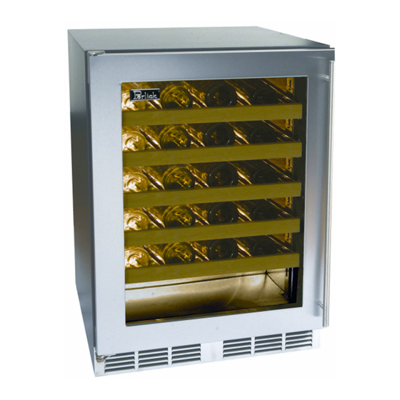
Perlick HC24BB Operation & Installation Manual
Hide thumbs
Also See for HC24BB:
- Service manual (125 pages) ,
- Operation & installation manual (23 pages) ,
- Use & care manual (14 pages)
Summary of Contents for Perlick HC24BB
- Page 1 Luxury Operation & Installation Manual C-Series (HC24 models) HC24RB HC24BB HC24WB Form No. Z2303 Rev. 09/17/2012...
-
Page 3: Table Of Contents
In the event you require assistance, products on the market. Perlick’s product offering gives you the please contact the dealer where you purchased your unit. -
Page 4: General Precautions
CAUTION Use only genuine Perlick replacement parts. Imitation parts can WARNING damage the unit, and may void the warranty. • Never attempt to repair or perform maintenance on the unit until the electricity has been disconnected. -
Page 5: Overall Dimensions And Drawings
16 " " 8 MILWAUKEE, WI 53223 *3 7/8" 8 " 4 " PRINTED PROPERTY OF THE PERLICK CORP. 20" NOT TO BE COPIED OR USED DETRIMENTAL TO OUR INTERESTS 4/20/2012 J:\Dwg\95000\95079.slddrw Leg levelers can add 3/4" to these dimensions when fully extended. -
Page 6: Preparing The Space
PREPARING THE SPACE Where a two-prong wall receptacle is encountered or a longer Make sure that the space where the Perlick cabinet(s) is/are to be installed is properly prepared. Refer to Figures 1 and 2 (page 5) to power cord is required, contact a qualified electrician to have it ensure proper space dimensions and electrical service are correct replaced in accordance with applicable electrical codes. -
Page 7: Anti-Tip Brackets
Operation & Installation Manual C-Series (HC24 models) ANTI-TIP BRACKETS Figure 5 - 24” Anti-Tip Kit Drawing WARNING Unit may tip forward if loaded racks/shelves are all pulled out at the same time. To prevent tipping and provide a stable installation, the unit must be secured in place with the anti-tip brackets provided with the unit. -
Page 8: Installation
Operation & Installation Manual C-Series (HC24 models) INSTALLATION Figure 6 - Leveling CAUTION Finished flooring should be protected with the appropriate material to avoid damage from moving the unit. If unit has been laid on its back or sides, place unit upright and allow minimum of 24 hours before connecting power. -
Page 9: Shelving
Operation & Installation Manual C-Series (HC24 models) TOE PLATE INSTALLATION When the unit is secured in place, install the louvered toe plate. Adjusting Full-extension Shelving Secure louvered toe plate by snapping the latch into the latch 1. Pull the shelf out to its farthest position. Locate the tabs in the catch on the unit. - Page 10 Operation & Installation Manual C-Series (HC24 models) Figure 8- Toe Plate Wood Overlay Template Figure 12 - Lock installation Mounting bracket Lock strike Lockwasher Lock body Screw Lock bracket...
-
Page 11: Door Options
The panel and door handles are supplied by the panel (page 17). customer. All Perlick units accept any of the above door configurations and are fully interchangable. IMPORTANT NOTE: Glass with stainless trim and glass with wood trim may sweat in conditions with relative humidity over 75%. - Page 12 Operation & Installation Manual C-Series (HC24 models) Figure 13 - Solid wood overlay panel template...
- Page 13 Operation & Installation Manual C-Series (HC24 models) Figure 14 - Glass wood overlay panel template...
- Page 14 Operation & Installation Manual C-Series (HC24 models) Figure 15 - Wood overlay drawer panel template...
- Page 15 Operation & Installation Manual C-Series (HC24 models) Figure 16 - Lock installation, solid wood overlay door panel...
- Page 16 Operation & Installation Manual C-Series (HC24 models) Figure 17 - Lock installation, wood overlay glass door panel...
- Page 17 Operation & Installation Manual C-Series (HC24 models) Figure 18 - Lock installation, wood overlay drawer panel...
-
Page 18: Handle/Wood Panel Installation
your smart phone to watch a How-To video on how to install Wood Overlay panels onto Perlick doors, otherwise, follow the instructions below. ... -
Page 19: Operation
The cabinet also comes standard with a manual light switch located next to the light for displaying your products Your Perlick unit is pre-set in order to achieve the recommended through a glass door. temperature range when installed in a 70°F ambient room temperature. -
Page 20: Cleaning The Condenser
Operation & Installation Manual C-Series (HC24 models) CAUTION Do not use abrasive cleaners or cloths on any of the interior or exterior surfaces or removable parts. Cleaning the Condenser The condenser should be cleaned every three (3) months. The condenser is located behind the toe plate (Figure 6, page 10). Remove the toe plate and use a soft bristle brush and vacuum to remove the dust and lint. - Page 21 Use only genuine Perlick replacement parts and accessories. Genuine Perlick parts and accessories are designed to work correctly with Perlick products and offer superior service life. The use of non-Perlick parts can damage the unit and may void the warranty •...
-
Page 22: Warranty
ENTIRE PRODUCT - Full Three Year Warranty*: For three (3) years from date of original purchase, Perlick Corporation’s warranty covers all parts and labor to repair or replace any part of the product, which proves to be defective in material and workmanship. - Page 23 Perlick’s sole liability and your exclusive remedy under this warranty are set forth in the initial paragraph above.


Need help?
Do you have a question about the HC24BB and is the answer not in the manual?
Questions and answers