Extron electronics XTP II CrossPoint 6400 Setup Manual
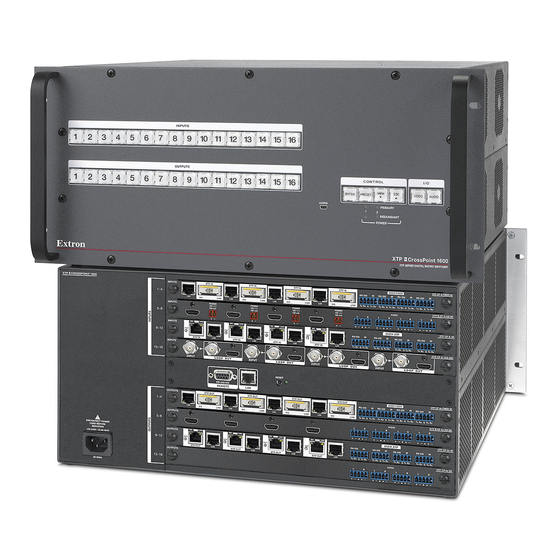
Configurable digital video matrix switchers
Hide thumbs
Also See for XTP II CrossPoint 6400:
- User manual (169 pages) ,
- Setup manual (60 pages) ,
- User manual (113 pages)

Related Manuals for Extron electronics XTP II CrossPoint 6400


Summary of Contents for Extron electronics XTP II CrossPoint 6400
- Page 1 Setup Guide Matrix Switchers XTP II CrossPoint 1600 XTP II CrossPoint 3200 XTP II CrossPoint 6400 Configurable Digital Video Matrix Switchers 68-1736-51 Rev. B 01 16...
-
Page 2: Safety Instructions
Safety Instructions Safety Instructions • English Инструкция по технике безопасности • Русский WARNING: This symbol, , when used on the product, is intended to alert the user of the presence of uninsulated dangerous voltage ПРЕДУПРЕЖДЕНИЕ: Данный символ, , если указан within the product’s enclosure that may present a risk of electric на... - Page 3 “Extron Safety and Regulatory Compliance Guide” on the Extron website. Class 1 Laser Product Any service to this product must be carried out by Extron Electronics and its qualified service personnel. CAUTION: Using controls, making adjustments, or performing procedures in a manner other than what is specified herein may result in hazardous radiation exposure.
- Page 4 Battery Notice These products contain batteries. Do not open the unit to replace the battery. If the battery needs replacing, return the entire unit to Extron (for the correct address, see the Extron Warranty section on the last page of this guide). CAUTION: Risk of explosion.
- Page 5 Trademarks All trademarks mentioned in this guide are the properties of their respective owners. The following registered trademarks, registered service marks, and trademarks are the property of RGB Systems, Inc. or Extron Electronics: Registered Trademarks (®) AVTrac, Cable Cubby, CrossPoint, DTP, eBUS, EDID Manager, EDID Minder, Flat Field, FlexOS,...
- Page 7 Contents ......22 ........1 Remote Control Introduction Selected SIS Commands ....22 About this Guide ........1 Establishing a Network About the XTP II CrossPoint (Ethernet) Connection ....22 Matrix Switchers ......... 1 Number of Connections ....23 Endpoint Configuration ....3 Establishing a USB Port Swapping Boards and Connection ........
- Page 8 viii XTP II CrossPoint 1600, 3200, and 6400 • Contents...
-
Page 9: Introduction
Introduction This section gives an overview of the Extron XTP II CrossPoint 1600, XTP II CrossPoint 3200, and XTP II CrossPoint 6400 Series configurable matrix switchers and describes their features. Topics that are covered include: • About this Guide •... - Page 10 Input Boards Output Boards XTP CP 4i (twisted pair [TP] inputs) XTP CP 4o (TP outputs) XTP CP 4i Fiber 4K (fiber optic inputs) XTP CP 4o Fiber 4K (fiber optic outputs) XTP II CP 4i HD 4K PLUS (HDMI 4K inputs) XTP II CP 4o HD 4K PLUS (HDMI 4K outputs) XTP CP 4i HDMI (HDMI inputs) XTP CP 4o HDMI (HDMI outputs)
-
Page 11: Endpoint Configuration
1, for a total of 32 inputs and 32 outputs. The XTP II CrossPoint 6400 can support up to 16 input boards and 16 output boards of any of the type listed in table 1, for a total of 64 inputs and 64 outputs. -
Page 12: Installation
Input or output positions are 1 - 4 in the left space and 29 - 32 in the right space. For the XTP II CrossPoint 6400, input and outputs 33 - 64 are in second blocks of boards. -
Page 13: Inputs And Outputs
REMOTE RS 232/RS422 LINK RESET 100-240V --A MAX 50-60Hz DISCONNECT POWER CORD BEFORE SERVICING Figure 3. XTP II CrossPoint 3200 Switcher Rear Panel ATTENTION: • Unplug the product and other devices before proceeding. avant de procéder • Débranchez le produit et les autres appareils Inputs and Outputs figure 2 NOTE:... - Page 14 33-36 37-40 41-44 45-48 49-52 53-56 57-60 61-64 INPUTS OUTPUTS G G G DISCONNECT POWER BEFORE SERVICING 220-240V 50-60 Hz XX.XA MAX Figure 4. XTP II CrossPoint 6400 Switcher Rear Panel XTP II CrossPoint 1600, 3200, and 6400 • Installation...
- Page 15 figure 2 figure 3 NOTE: See item on page 4, on page 5, and figure 4 on page 6. XTP power indicators — Indicate the status of the power over XTP (PoX) provided to the endpoint as follows: Lit green — The board is providing XTP power to the endpoint. Lit amber —...
- Page 16 figure 2 figure 3 NOTE: See item on page 4, on page 5, and figure 4 on page 6. XTP II CP 4i HD 4k PLUS and XTP CP 4i HDMI (HDMI input boards) INPUTS XTP II CP 4i HD 4K PLUS AUDIO XTP CP 4i HDMI AUDIO...
- Page 17 figure 2 figure 3 NOTE: See item on page 4, on page 5, and figure 4 on page 6. Audio (local audio) connectors — Connect balanced or unbalanced stereo audio inputs to these 3.5 mm, Local audio 5-pole captive screw connectors (see connectors on page 16 to wire the connectors).
- Page 18 figure 2 figure 3 NOTE: See item on page 4, on page 5, and figure 4 on page 6. XTP power indicators — Indicate the status of the PoX provided to the endpoint as follows: Lit green — The board is providing XTP power to the endpoint. Lit amber —...
- Page 19 figure 2 figure 3 NOTE: See item on page 4, on page 5, and figure 4 on page 6. XTP II CP 4o HD 4k PLUS and XTP CP 4o HDMI (HDMI output boards) OUTPUTS XTP II CP 4o HD 4K PLUS AUDIO XTP CP 4o HDMI AUDIO...
-
Page 20: Remote Control
Remote Control NOTE: See item and item figure 2 on page 4, figure 3 page 5, and figure 4 on page 6. LAN (Ethernet) port — If desired, connect a network WAN or LAN hub, a control system, or a computer to the Ethernet RJ-45 port (see TP connectors on the next page to wire the connector). -
Page 21: Additional Connector Information
ATTENTION: • Extron recommends that this procedure be performed by a licensed electrician only. See the XTP II CrossPoint 1600, 3200, and 6400 Series User Guide, available at www.extron.com , for installation instructions, warnings, and other important information. • Extron recommande que cette tâche soit exécutée par un électricien agréé... - Page 22 Switcher and XTP board LAN cables The LAN ports require CATx, crossover or patch cables. XTP board XTP cables ATTENTION: • Do not connect these boards to a computer data or telecommunications network. • Ne connectez pas ces cartes à des données informatiques ou à un réseau de télécommunications.
- Page 23 RS-232 and IR connectors Figure 6 shows how to wire the RS-232 and IR connector. IR Device Tx/Rx Pins RS-232 Device Figure 6. RS-232 and IR Connector Wiring NOTES: • The length of exposed wires is important. The ideal length is 3/16 inch (5 mm).
- Page 24 Loosely place the included tie wrap around the HDMI connector and the LockIt lacing bracket (see on the previous page). While holding the connector securely against the lacing bracket, use pliers or similar tool to tighten the tie wrap ( ), then remove any excess length.
-
Page 25: Front Panel
Configuration port, a mini USB B port Primary and Redundant Power Supply LEDs — NOTES: • The XTP II CrossPoint 6400 and XTP II CrossPoint 3200 have four power supplies installed and indicated. • The XTP II CrossPoint 1600 has two power supplies installed and indicated in its standard configuration (only two LEDs lit). -
Page 26: Front Panel Operations
Front Panel Operations This section describes simple XTP II CrossPoint matrix switcher operation from the front panel. Topics that are covered include: • Creating a Tie • Saving or Recalling a Preset • Setting the Front Panel Locks (Executive Modes) •... -
Page 27: Saving Or Recalling A Preset
Saving or Recalling a Preset A "preset" is a configuration that has been stored. Save a preset — Press and hold the Preset button until it flashes. Save a 2 seconds PRESET PRESET preset Press and hold. The Preset button blinks. Recall a preset —... -
Page 28: Toggling Between Mode 2 And Mode 0
Selecting Lock Mode 2 or Toggling Between Mode 2 and Mode 0 NOTES: • If the switcher is in Lock mode 0 or mode 1, this procedure selects mode 2. The Preset , View , and Esc buttons flash twice. •... -
Page 29: Viewing And Adjusting The Audio Level
Viewing and Adjusting the Audio Level NOTES: • Gain and attenuation can be adjusted for local inputs only. • Volume can be adjusted for the local outputs only. Press and hold the Audio button until it flashes. 2 seconds AUDIO AUDIO Press and Audio button blinks. -
Page 30: Remote Control
Remote Control This section describes using the remote control features of the XTP II CrossPoint matrix switchers to control the devices. Topics that are covered include: • Selected SIS Commands • XTP System Configuration Program • Accessing the HTML Pages Selected SIS Commands You can use Simple Instruction Set (SIS) commands for operation and configuration of the switchers (see... -
Page 31: Number Of Connections
Number of Connections A switcher can have up to 200 simultaneous TCP connections, including all HTTP sockets and Telnet connections. When the connection limit is reached, the switcher accepts no new connections until some have been closed. No error message or indication is given that the connection limit has been reached. -
Page 32: Arrangement Of Command And Response Tables
Arrangement of Command and Response Tables The following pages present five command and response tables, each defining a subset of SIS commands and their responses, with examples where appropriate. The following tables are presented: • SIS Command and Response Table for Matrix Switcher Commands, starting on the next page —... -
Page 33: Table For Matrix Switcher Commands
SIS Command and Response Table for Matrix Switcher Commands Command SIS Command Response Additional Description (Host to Unit) (Unit to Host) Create ties • Commands can be entered back-to-back in a string, with no spaces. For example: 1*1!02*02&003*003%4*24$. NOTES: • The matrix switchers support 1-, 2-, and 3-digit numeric entries (1*1!, 02*02&, or 003*003%). - Page 34 Command SIS Command Response Additional Description (Host to Unit) (Unit to Host) Input video format (available for inputs on an XTP CP 4i VGA universal analog input board only) Set format Ityp Set input video format. The board reports the detected video format, , in response.
- Page 35 Command SIS Command Response Additional Description (Host to Unit) (Unit to Host) Tint (available for inputs on an XTP CP 4i VGA universal analog input board only) NOTE: Tint adjustments are available for NTSC S-video, and NTSC composite video inputs. Set a specific tint value Specify the tint adjustment.
- Page 36 Command SIS Command Response Additional Description (Host to Unit) (Unit to Host) Pixel phase (available for inputs on an XTP CP 4i VGA universal analog input board only) NOTE: Pixel phase adjustments are available for RBGHV and non-interlaced component video (YUVp) video inputs. Set a specific pixel sampling phase PHAS PhasI...
- Page 37 Command SIS Command Response Additional Description (Host to Unit) (Unit to Host) Analog input presets (available for inputs on an XTP CP 4i VGA universal analog input board only) NOTE: Analog input presets are a set of variables that can be saved. For the complete list, see the XTP II CrossPoint Switchers User Guide. X&...
- Page 38 Command SIS Command Response Additional Description (Host to Unit) (Unit to Host) Input audio selection X1!] Input audio selection AFMT AfmtI Example: I1*0AFMT AfmtI1*0 Auto (0): Digital audio takes priority over analog audio. X1!] View input audio selection AFMT View input audio all selections IAFMT Each is the enable or disable status of an output,...
- Page 39 Command SIS Command Response Additional Description (Host to Unit) (Unit to Host) Audio output volume X1%] Set the volume to a specific value •Vol 1*50v Example: Out01•Vol50 Set output 1 volume to 79%. X1%] Increment volume •Vol Increase volume by 1 step. Example: Out01•Vol51 X1%]...
- Page 40 Command SIS Command Response Additional Description (Host to Unit) (Unit to Host) Captive screw and Ethernet serial port insertion enables (available for inputs and outputs on XTP CP 4i , XTP CP 4o [XTP input and output], and XTP CP 4i fiber, and XTP CP 4o fiber boards only) Enable an input captive screw *0LRPT LrptI...
- Page 41 (XTP II CrossPoint 1600) = Input 1 through 16 2001 2016 through (XTP II CrossPoint 3200) = Input 1 through 32 2001 2032 through (XTP II CrossPoint 6400) = Input 1 through 64 2001 2064 through (XTP II CrossPoint 1600) = Output 1 through 16 2033 2048 through...
- Page 42 Command SIS Command Response Additional Description (Host to Unit) (Unit to Host) View video and audio mutes View output mutes Each response is the mute status of an output, starting from output 1. n = either 16, 32, or 64. Example : Audio is muted on outputs 2 and 3, video on output 5, and (XTP II CrossPoint 3200)
- Page 43 Command SIS Command Response Additional Description (Host to Unit) (Unit to Host) Information requests V X2& X X2* A X2& X X2*] X2& Information request In the response: V is the video matrix size. • X2& is the audio matrix size. X2(] Request part number See the www.extron.com, for part numbers.
-
Page 44: Sis Command And Response Table For Transmitter Endpoints
SIS Command and Response Table for Transmitter Endpoints NOTE: These commands allow you to control and monitor the HDMI transmitter endpoint from the matrix switcher. Command SIS Command Response Additional Description (Host to Unit to Endpoint) (Endpoint to Unit to Host) Audio routing selection NOTE: These commands select between the audio embedded in the digital video stream and the 2-channel analog audio. - Page 45 Command SIS Command Response Additional Description (Host to Unit to Endpoint) (Endpoint to Unit to Host) List Digital Sync Validation Processing (DSVP) List sync of all inputs 16, 32, or 64 ( s; each is the signal status of an input, starting from input 1.
-
Page 46: Sis Command And Response Table For Receiver Endpoints
SIS Command and Response Table for Receiver Endpoints NOTE: These commands allow you to control and monitor the HDMI receiver endpoint from the matrix switcher. Command SIS Command Response Additional Description (Host to Unit to Endpoint) (Endpoint to Unit to Host) HDCP status View output HDCP status HDCP... - Page 47 Command SIS Command Response Additional Description (Host to Unit to Endpoint) (Endpoint to Unit to Host) Audio mutes Audio mute, HDMI and S/PDIF Mute output embedded digital (audio off). Audio mute, analog Mute output analog (analog audio off). Audio mute, both Mute all output audio (digital and analog audio off).
- Page 48 Command SIS Command Response Additional Description (Host to Unit to Endpoint) (Endpoint to Unit to Host) Relay controls *1RELY Rely Turn on an endpoint relay Turn on relay in output *0RELY Rely Turn off an endpoint relay Turn off relay in output Toggle an endpoint relay *2RELY...
-
Page 49: Table For Switching Transmitter Endpoint
SIS Command and Response Table for Switching Transmitter Endpoint NOTE: These commands allow you to control and monitor the universal switcher endpoint from the matrix switcher. Command SIS Command Response Additional Description (Host to Unit to Endpoint) (Endpoint to Unit to Host) Input video format (available for endpoint input 1 only) Set format Ityp... - Page 50 Command SIS Command Response Additional Description (Host to Unit to Endpoint) (Endpoint to Unit to Host) Horizontal shift (available for endpoint input 1 only) Specify a horizontal position HCTR HctrI Set input horizontal position to Increment right +HCTR HctrI Shift the input right.
- Page 51 Command SIS Command Response Additional Description (Host to Unit to Endpoint) (Endpoint to Unit to Host) Input audio selection NOTE: These commands select between the audio embedded in the digital video stream and the 2-channel analog audio. X1!] Input audio selection AFMT AfmtI Example:...
-
Page 52: Sis Command And Response Table For Ip-Specific Commands
Command SIS Command Response Additional Description (Host to Unit to Endpoint) (Endpoint to Unit to Host) List Digital Sync Validation Processing (DSVP) List sync of all inputs 16, 32, or 64 ( s; each is the signal status of an input, starting from input 1. -
Page 53: Xtp System Configuration Program
XTP System Configuration Program Another way to operate the switcher is via the Windows -based XTP ® System Configuration software. For details on installing and operating the program, see the XTP System Configuration Software help file. Accessing the HTML Pages NOTES: •... - Page 54 Enter the appropriate administrator or user password in the Password field and click OK . The switcher downloads the HTML start-up page (see figure 12). The switcher is ready for operation via HTML remote control. Figure 12. HTML Startup Page XTP II CrossPoint 1600, 3200, and 6400 •...
-
Page 55: Configuration
For a board, orient the board to be installed horizontally (XTP II CrossPoint 1600) or vertically (XTP II CrossPoint 3200 and XTP II CrossPoint 6400) and so that the IN or OUT silkscreen on the back panel is right side up. - Page 56 Align with Plastic Guides D IO Knurled Knobs Figure 13. Board Removal and Installation For a board, gently seat the board in the backplane. Use a screwdriver to tighten the left and right knurled knobs to lock the board or panel in place. XTP II CrossPoint 1600, 3200, and 6400 •...
- Page 59 In no event will Extron Electronics be liable for direct, indirect, or consequential damages resulting from any defect in this product even if Extron Electronics has been advised of such damage.
- Page 60 +1.919.850.1001 FAX +81.3.3511.7655 +4000.EXTRON +81.3.3511.7656 FAX +4000.398766 Inside China Only Extron Asia Extron Middle East Extron Korea +800.7339.8766 +971.4.2991800 +82.2.3444.1571 +86.21.3760.1568 Inside Asia Only +971.4.2991880 FAX +82.2.3444.1575 FAX +86.21.3760.1566 FAX +65.6383.4400 +65.6383.4664 FAX © 2016 Extron Electronics All rights reserved. www.extron.com...
Need help?
Do you have a question about the XTP II CrossPoint 6400 and is the answer not in the manual?
Questions and answers