
Related Manuals for Extron electronics CrossPoint 124


Summary of Contents for Extron electronics CrossPoint 124
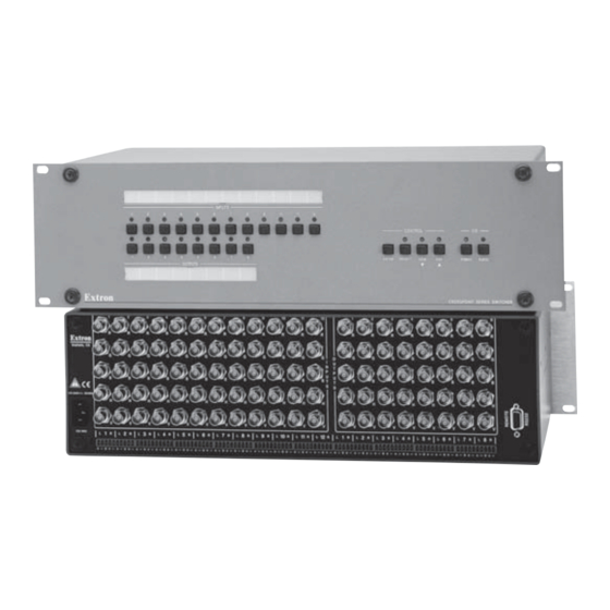
- Page 1 CrossPoint Matrix Switchers CrossPoint 84, 88, 124, 128, 168, and 1616 HV and HVA 68-353-02 Rev. E Printed in the USA 01 04...
- Page 2 Precautions Safety Instructions • English This symbol is intended to alert the user of important operating and maintenance (servicing) instructions in the literature provided with the equipment. This symbol is intended to alert the user of the presence of uninsulated dangerous voltage within the product's enclosure that may present a risk of electric shock.
- Page 3 Quick Start — CrossPoint Matrix Switchers Installation Step 1 Mount the switcher in a rack. Step 2 Turn off power to the input and output devices, and remove the power cords from them. Step 3 Cable the switcher for RGBHV, RGBS, RGsB, RsGsBs, component video , S-video, or composite video input and output (3).
-
Page 4: Front Panel Controls
Quick Start — CrossPoint Matrix Switchers, cont’d Front Panel Controls Input and output buttons and LEDs select and identify inputs and outputs. Input buttons also select presets. On HVA models, the output LEDs also display the audio level of the selected input. Enter button saves changes when you change the configuration. -
Page 5: Table Of Contents
Table of Contents Chapter 1 • Introduction About the CrossPoint Series Matrix Switchers Features ... 1-3 Chapter 2 • Installation ... 2-1 Rack Mounting the Switcher Cabling and Rear Panel Views Power connection ... 2-2 Video input and output connections ... 2-3 Audio input and output connections (HVA models only) ... - Page 6 Table of Contents, cont’d Chapter 4 • Programmer’s Guide Host-to-Switcher Instructions Switcher-Initiated Messages Switcher Error Responses Using the Command/Response Table Command/Response Table Chapter 5 • Matrix Software Matrix Switcher+ Control Program Installing the software ... 5-2 Using the software ... 5-2 Overview ...
-
Page 7: Chapter 1 • Introduction
CrossPoint Matrix Switchers Chapter One Introduction About the CrossPoint Series Matrix Switchers Features... -
Page 8: About The Crosspoint Series Matrix Switchers
• CrossPoint 84 (eight inputs by four outputs) • CrossPoint 88 (eight inputs by eight outputs) • CrossPoint 124 (twelve inputs by four outputs) • CrossPoint 128 (twelve inputs by eight outputs) • CrossPoint 168 (sixteen inputs by eight outputs) •... -
Page 9: Features
Stereo audio, balanced or unbalanced, on 3.5 mm, 5-pole captive screw terminals (HVA models). Bandwidth — Bandwidth is a minimum of 200 MHz (-3dB), fully loaded. This high bandwidth allows Extron’s switchers to switch everything from NTSC video to high-resolution computer displays. Class Room 105... - Page 10 Introduction, cont’d Operational flexibility — Operations such as input/output selection, setting of presets, and adjustment of audio levels can be performed on the front panel or over the RS-232/RS-422 link. The RS-232/RS-422 link allows remote control via a control system. •...
- Page 11 Remote control — The CrossPoint switchers are remote controllable, using the MKP 1000 master control keypad and any combination of MCP 1000 slave control panels and/or MKP 1000 slave control keypads. The remote control devices are easy to use and provide tactile buttons for quick selection. Each MCP 1000 can be used for one-touch switching for a particular output and selecting global presets.
- Page 12 Introduction, cont’d CrossPoint Matrix Switchers • Introduction...
-
Page 13: Chapter 2 • Installation
CrossPoint Matrix Switchers Chapter Two Installation Rack Mounting the Switcher Cabling and Rear Panel Views... -
Page 14: Rack Mounting The Switcher
Installation Installation, cont’d Rack Mounting the Switcher The CrossPoint 84, 88, 124, and 128 Matrix Switchers are housed in rack-mountable, 3U high, 19” wide metal enclosures. The CrossPoint 168 and 1616 are in 6U high enclosures. The appropriate rack mount kit is included with each switcher. Rack mount the switcher as follows: Insert the switcher into the rack, align the holes in the mounting bracket with those of the rack. -
Page 15: Video Input And Output Connections
RGBHV video outputs — Connect RGBHV video outputs to these BNC connectors for each output. The CrossPoint Series switchers can also switch RGBS, RGsB, RsGsBs, component video, S-video, or composite video by using four, three, two, or one BNC. If switching a video format other than RGBHV, ensure that the same video planes (R, G, B, H/HV, and/or V) are used on the switcher output as on the input. -
Page 16: Rs-232/422 Connection
Figure 2-5 — Captive screw connector wiring for audio output CAUTION By default, the audio output follows the video switch. Audio breakaway, commanded via the front panel, under RS-232/422 control, or Windows- based control program, allows you to select from any one of the audio input sources. - Page 17 INPUTS Figure 2-6 — Rear panel view, CrossPoint 84HV INPUTS Figure 2-7 — Rear panel view, CrossPoint 84HVA INPUTS Figure 2-8 — Rear panel view, CrossPoint 88HV INPUTS Figure 2-9 — Rear panel view, CrossPoint 88HVA Figure 2-10 — Rear panel view, CrossPoint 124HV CrossPoint Matrix Switchers •...
- Page 18 Installation, cont’d Figure 2-11 — Rear panel view, CrossPoint 124HVA Figure 2-12 — Rear panel view, CrossPoint 128HV Figure 2-13 — Rear panel view, CrossPoint 168HV CrossPoint Matrix Switchers • Installation 1 3 5 7 1 3 5 7...
- Page 19 1 3 5 7 1 3 5 7 Figure 2-14 — Rear panel view, CrossPoint 168HVA 1 3 5 7 1 3 5 7 Figure 2-15 — Rear panel view, CrossPoint 1616HV CrossPoint Matrix Switchers • Installation...
- Page 20 Installation, cont’d CrossPoint Matrix Switchers • Installation...
-
Page 21: Chapter 3 • Operation
CrossPoint Matrix Switchers Chapter Three Operation Front Panel Controls and Indicators Front Panel Operations Rear Panel Controls Troubleshooting Worksheets... -
Page 22: Front Panel Controls And Indicators
Operation Operation, cont’d Front Panel Controls and Indicators The front panel controls (figure 3-1 and figure 3-2) are grouped into two sets. The input and output buttons and LED indicators are grouped on the left side of the control panel. The control buttons and input/output (I/O) selection buttons and indicators are grouped on the right side of the panel. -
Page 23: Input Buttons, Output Buttons, And Leds
Current configuration — The configuration that is currently being used (also called configuration 0). Global memory preset — A configuration that has been stored. Up to twelve global memory presets (CrossPoint 84, 88, 124, and 128) or sixteen global memory presets (CrossPoint 168 and 1616) can be stored in memory. The input buttons select the desired preset memory location to load or retrieve a preset. -
Page 24: I/O Controls
Operation, cont’d As a secondary function on HVA models, the Esc button increments the audio level of the selected input. In audio adjust mode, the Esc LED indicates a positive (+) gain value. A more detailed explanation of audio level adjustment is included in Viewing and adjusting the audio level (HV A models only) on page 3-13. -
Page 25: Front Panel Operations
Front Panel Operations The following paragraphs detail the power-up process and then provide sample procedures for creating ties, sets of ties, and configurations; changing a configuration; viewing ties, sets of ties, and configurations; saving a preset; recalling a preset; and viewing and adjusting the audio level. Power On all models, power is automatically applied when the power cord is connected to an AC source. - Page 26 Operation, cont’d Example 1: Create a set of video and audio ties See figure 3-4 and the following steps for an example in which input 5 is tied to outputs 3, 4, and 8. This example assumes that there are no ties in the current configuration. Press OUTPUTS Press...
-
Page 27: Example 3: Remove A Tie From A Set Of Video And Audio Ties
output 3, output 4, and output 8; and audio input 5 tied to audio output 3, output 4, and output 8. LED key: Press INPUTS OUTPUTS Press Figure 3-5 — Example 2: Adding a video tie Example 3: Remove a tie from a set of video and audio ties See figure 3-6 and the following steps for an example in which an existing audio tie is removed from the current configuration. -
Page 28: Viewing A Configuration
Operation, cont’d OUTPUTS Figure 3-7 — Example 3, step D: Removing an audio tie Press and release the Enter button. The input and output LEDs turn off. The current configuration is now defined as video input 5 tied to video output 1, output 3, output 4, and output 8;... - Page 29 LED key: = off, = on, = flashes once INPUTS OUTPUTS Figure 3-8 — Example 4: Viewing the current configuration, no input selected Example 4 shows the process of viewing the current configuration after the steps in Examples 1, 2, and 3 have been performed. Press and release the Esc button.
-
Page 30: Muting And Unmuting Video And/Or Audio
Operation, cont’d that the selected output LED, the tied input LED (input 5), and the output LEDs light for all of the outputs that are tied to the input. Press and release the RGBHV button to toggle the Video LED off (figure 3-10). If audio is broken away, the Audio LED stops blinking and lights. -
Page 31: Example 5: Muting And Unmuting An Output
blink to indicate the mute or return to their previous state to indicate the unmute. Press and release the View button to return to normal switcher operation. You can mute video and audio, video-only, or audio-only outputs. Pressing and releasing the RGBHV and Audio buttons toggles each selection on and off. -
Page 32: Using Presets
Operation, cont’d OUTPUTS Hold Hold Hold Hold Figure 3-12 — Example 5, step D: Muting and unmuting outputs Using presets The current configuration (configuration 0) can be saved as a preset in any one of 12 preset memory addresses (CrossPoint 84, 88, 124, and 128) or 16 preset memory addresses (CrossPoint 168 and 1616). -
Page 33: Viewing And Adjusting The Audio Level (Hva Models Only)
Press and release the Esc button. The Esc LED flashes once. Press and hold the Preset button for approximately 2 seconds until the Preset LED begins to blink, then release the Preset button. Press and release the input 1 button. The input 1 LED flashes once. The Preset LED turns off. - Page 34 Operation, cont’d the CrossPoint 168 and 1616, but the steps for displaying the value are the same. For this reason, figure 3-16 and figure 3-18 show the indications displayed on the CrossPoint 168 and 1616 without duplicating all of the actions shown in figure 3-15 and figure 3-17.
- Page 35 LED key: = off (value 0dB), = on (value 1dB) INPUTS OUTPUTS +8dB Figure 3-16 — +8dB displayed, CrossPoint 168 and 1616 Press and release the View ( displayed in the output LEDs by 1dB. Press and release the View ( several more times to decrease the audio level displayed in the output LEDs by an additional 1dB per button push.
-
Page 36: Front Panel Security Lockout (Executive Mode)
CrossPoints have two sets of sync termination switches; one for horizontal or combined sync and a second set for vertical sync. Each switch provides the option of selecting either 510 ohms or 75 ohms. The 75 ohms position is required only for an input with non-TTL sync, greater than 5V p-p. -
Page 37: General Checks
General checks Ensure that all devices are plugged in and powered on. The switcher is receiving power if one of the input LEDs is lit. Ensure an active input is selected for output on the switcher. Ensure that the proper signal format is supplied. Check the cabling and make corrections as necessary. -
Page 38: Worksheet Example 2: Drawing Ties
Operation, cont’d Worksheet example 2: Drawing ties Figure 3-20 continues from worksheet example 1 by showing the video and audio ties that make up the configuration of preset 3, a solid ink line shows video ties, and a dashed pencil line shows the audio ties. In this example, the image of the presenter, from the main podium camera (input 1), is displayed in the main hall (output 1), to the overflow crowd in the conference room (output 4), and in the lobby (output 8). -
Page 39: Worksheet Example 3: Test Configuration
Worksheet example 3: Test configuration The A/V system in our fictional organization needs to be fine tuned on a regular basis. Figure 3-21 shows a typical test configuration, with an Extron video test generator (input 12) generating a test pattern to all monitors (outputs 1, 2, 3, 4, and 8). - Page 40 Operation, cont’d 3-20 CrossPoint Matrix Switchers • Operation...
- Page 41 CrossPoint Matrix Switchers • Operation 3-21...
- Page 42 Operation, cont’d 3-22 CrossPoint Matrix Switchers • Operation...
-
Page 43: Chapter 4 • Programmer's Guide
CrossPoint Matrix Switchers Chapter Four Programmer’s Guide Host-to-Switcher Instructions Switcher-Initiated Messages Switcher Error Responses Using the Command/Response Table Command/Response Table... -
Page 44: Host-To-Switcher Instructions
Programmer’s Guide Programmer’s Guide, cont’d The switcher’s rear panel RS-232/RS-422 connector (figure 4-1) can be connected to the serial port output of a host device such as a computer, RS-232 capable PDA, or control system. This connection makes software control of the switcher possible. Female Figure 4-1 —... -
Page 45: Switcher Error Responses
The switcher does not expect a response from the host, but, for example, the host program might request a new status. Switcher Error Responses When the switcher receives an SIS command and determines that it is valid, it performs the command and sends a response to the host device. If the switcher is unable to perform the command because the command is invalid or contains invalid parameters, the switcher returns an error response to the host. -
Page 46: Command/Response Table
• = Space = Input number 01 – 08 (CrossPoint 84, 88); 01 – 12 (CrossPoint 124, 128); 01 – 16 (CrossPoint 168, 1616) = Output number 01 – 04 (CrossPoint 84, 124); 01 – 08 (CrossPoint 88, 128, 168);... - Page 47 End direct write of global presets Quick recall preset This sequence of commands forces the switcher to perform a complete backplane switch within 60 msecs of receipt of the Quick recall command. The switcher ignores any invalid command or non-switching commands received between the Start and End commands.
- Page 48 Programmer’s Guide, cont’d Command/response table for SIS commands (Cont’d) Command ASCII Command Response (host to switcher) Resets Reset global presets Reset audio levels Reset all mutes Reset whole switcher View ties, gain, and presets View video output tie Example: View audio output tie Example: View gain for input Example:...
-
Page 49: Chapter 5 • Matrix Software
CrossPoint Matrix Switchers Chapter Five Matrix Software Matrix Switcher+ Control Program Button-Label Generator... -
Page 50: Matrix Switcher+ Control Program
Matrix Software Matrix Software, cont’d Two software programs accompany the CrossPoint Series switchers: • The Extron Matrix Switchers Control Program (Extron part number 29-015- 01), which communicates with the switcher via the RS-232/RS-422 port, provides an easy way for you to set up ties and sets of ties. If your CrossPoint Series switcher was previously set up for RS-232, and your computer comm port uses RS-422, you must change the switcher cabling to match the computer interface. - Page 51 Figure 5-1 — Extron Matrix Switcher+ Control Program window (blank) Figure 5-2 — Sample program window (complete) To make the control program easier to use, assign a device icon to each input and output. Click on a box that represents an input or output, and drag the desired icon onto the box from the icon palette that appears.
- Page 52 Matrix Software, cont’d Go — Activates the selected preset as the current configuration. Save as — Allows the current set of ties to be saved as a preset. Enter the preset number when prompted to do so. Changes – Take — Allows you to save to file any changes made to the displayed configuration.
-
Page 53: Using Emulation Mode
Using emulation mode Emulation mode allows you to set up the software without attaching the switcher to the computer. To use emulation mode, do the following: Start the program as described in step 1 on page 5-2. Choose Emulate, and click OK. Choose an emulation file to open, and click OK. - Page 54 Matrix Software, cont’d Figure 5-3 — Extron’s Button-Label Generator window CrossPoint Matrix Switchers • Matrix Software...
-
Page 55: Appendix A • Specifications
CrossPoint Matrix Switchers A ppendix A Specifications Specifications Part Numbers... -
Page 56: Video Input
Specifications Specifications, cont’d Video Routing ... 84 Series ... 8 x 4 matrix 88 Series ... 8 x 8 matrix 124 Series ... 12 x 4 matrix 128 Series ... 12 x 8 matrix 168 Series ... 16 x 8 matrix 1616 Series ... -
Page 57: Audio Output
Audio — audio models only Routing ... 84 Series ... 8 x 4 stereo matrix 88 Series ... 8 x 8 stereo matrix 124 Series ... 12 x 4 stereo matrix 128 Series ... 12 x 8 stereo matrix 168 Series ... 16 x 8 stereo matrix 1616 Series ... -
Page 58: Crosspoint Part Numbers
Specifications, cont’d 168/1616 Series ... 10.5" H x 17.0" W x 9.7" D (6U high, full rack width) (26.7 cm H x 43.2 cm W x 24.6 cm D) (Depth excludes connectors. Width excludes rack ears.) Product weight 84/88/124/128 Series ... 14.8 lbs (6.7 kg) 168/1616 Series ... -
Page 59: Cables
Cables When using signals with a scanning frequency of 15-125 kHz and running distances of 100 feet or more, use high resolution BNC cables to achieve maximum performance. Bulk cable Extron Part RG6 super high resolution cable Bulk RG6-1, 500’ Bulk RG6-1, 1000’... - Page 60 Specifications, cont’d Extron Part BNC-5 Mini HR Cable BNC-5-25’ MHR (25 feet/7.5 meters) BNC-5-50’ MHR (50 feet/15.0 meters) BNC-5-75’ MHR (75 feet/23.0 meters) BNC-5-100’ MHR (100 feet/30.0 meters) BNC-5-150’ MHR (150 feet/45.0 meters) BNC-5-200’ MHR (200 feet/60.0 meters) BNC-5-250’ MHR (250 feet/75.0 meters) BNC-5-300’...
-
Page 61: Appendix B • Reference Information
CrossPoint Matrix Switchers A ppendix B Reference Information Hardware Upgrades Button Labels... -
Page 62: Hardware Upgrades
Reference Information Reference Information, cont’d Hardware Upgrades This appendix contains procedures for performing hardware maintenance procedures such as swapping the RS-232 and RS-422 ports, installing a new firmware update, and replacing the fuse. Opening the switcher Before you can perform any of the hardware upgrade procedures, you must open the switcher. -
Page 63: Opening The Crosspoint 168 And 1616
Opening the CrossPoint 168 and 1616 To open the CrossPoint 168 or 1616 switcher, do the following: Disconnect the power cord from the switcher. Do not strain the three internal cables connected to the front panel. Too CAUTION much strain can be damage the cables. Do not touch the components inside the switcher without being CAUTION electrically grounded. -
Page 64: Closing The Switcher
Reference Information, cont’d Closing the switcher Reinstall any cables removed. To plug a self latching cable into the desired Ribbon cable Self-latching receptacle Place the top cover (CrossPoint 84, 88, 124, and 128) and/or front cover (all models) in place and replace all the screws removed in Opening the switcher on page B-2. -
Page 65: Installing A Firmware Update
If the switcher was removed from a rack, remove its power cord, reattach the switcher to the rack, and reconnect the power cord. Reconnect the input and output cables. Installing a firmware update The IC that contains the firmware for the matrix switcher also contains the memory in which presets and audio levels are saved. -
Page 66: Replacing The Ac Fuse (Crosspoint 84, 88, 124, And 128 Only
Reference Information, cont’d Reinitialize the switcher to recognize the new IC as follows: Connect the power cord to the AC power source. Press and hold the Enter button while you connect the power cord to the switcher. Observe that the Input, Output, Preset, View, and Esc LEDs all flash. Release the Enter button. - Page 67 CrossPoint Matrix Switchers • Reference Information...
- Page 68 Reference Information, cont’d CrossPoint Matrix Switchers • Reference Information...
-
Page 69: Fcc Class A Notice
Note: This equipment has been tested and found to comply with the limits for a Class A digital device, pursuant to part 15 of the FCC Rules. These limits are designed to provide reasonable protection against harmful interference when the equipment is operated in a commercial environment. - Page 70 Extron Electronics, USA 1230 South Lewis Street Anaheim, CA 92805 714.491.1500 www.extron.com Fax 714.491.1517 Extron Electronics, Europe Extron Electronics, Asia Beeldschermweg 6C 135 Joo Seng Road, #04-01 3821 AH Amersfoort PM Industrial Building The Netherlands Singapore 368363 +31.33.453.4040 +65.6383.4400 Fax +31.33.453.4050 Fax +65.6383.4664 ©...
Need help?
Do you have a question about the CrossPoint 124 and is the answer not in the manual?
Questions and answers