Extron electronics XTP II CrossPoint 1600 User Manual
Configurable digital video matrix switchers
Hide thumbs
Also See for XTP II CrossPoint 1600:
- Setup manual (60 pages) ,
- User manual (113 pages) ,
- Setup manual (4 pages)

Related Manuals for Extron electronics XTP II CrossPoint 1600


Summary of Contents for Extron electronics XTP II CrossPoint 1600
- Page 1 User Guide Matrix Switchers XTP II CrossPoint 1600 XTP II CrossPoint 3200 XTP II CrossPoint 6400 Configurable Digital Video Matrix Switchers 68-1736-02 Rev. A 09 15...
- Page 2 Safety Instructions Safety Instructions • English Инструкция по технике безопасности • Русский WARNING: This symbol, , when used on the product, is intended to ПРЕДУПРЕЖДЕНИЕ: Данный символ, , если указан alert the user of the presence of uninsulated dangerous voltage within the на...
- Page 3 FCC Class A Notice This equipment has been tested and found to comply with the limits for a Class A digital device, pursuant to part 15 of the FCC rules. The Class A limits provide reasonable protection against harmful interference when the equipment is operated in a commercial environment. This equipment generates, uses, and can radiate radio frequency energy and, if not installed and used in accordance with the instruction manual, may cause harmful interference to radio communications.
- Page 4 Conventions Used in this Guide Notifications The following notifications are used: WARNING: Potential risk of severe injury or death. AVERTISSEMENT : Risque potentiel de blessure grave ou de mort. ATTENTION: • Risk of property damage. • Risque de dommages matériels. NOTE: A note draws attention to important information.
- Page 5 Copyright © 2015 Extron Electronics. All rights reserved. Trademarks All trademarks mentioned in this guide are the properties of their respective owners. The following registered trademarks, registered service marks, and trademarks are the property of RGB Systems, Inc. or Extron Electronics: (®)
-
Page 7: Table Of Contents
Viewing and Adjusting the Analog Output Volume ....... 57 Setting the Front Panel Locks (Executive Modes) ............. 62 Performing a System Reset from the Front Panel ............63 Background Illumination......64 XTP II CrossPoint 1600, 3200, and 6400 Switchers • Contents... - Page 8 Gateways ..........159 Analog and Remote Devices ....159 IP Addresses and Octets ......159 Subnet Masks and Octets ....... 160 Determining Whether Devices Are on the Same Subnet ....... 160 XTP II CrossPoint 1600, 3200, and 6400 Switchers • Contents viii...
-
Page 9: Introduction
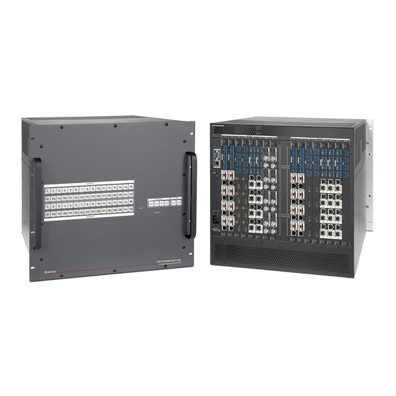
XTP II CrossPoint 1600 Matrix Switcher (see figure 1), CrossPoint 3200 Matrix Switcher, and XTP II CrossPoint 6400 Matrix Switcher. These customizable matrix switchers support up to 16 (XTP II CrossPoint 1600), 32 (XTP II CrossPoint 3200), or 64 (XTP II CrossPoint 6400) inputs and outputs. -
Page 10: About The Xtp Ii Crosspoint Switchers
The XTP II CrossPoint models are assembled from user-installed and hot-swappable input and output boards in the following quantities: • XTP II CrossPoint 1600 — Supports up to four input boards and four output boards. • XTP II CrossPoint 3200 — Support up to eight input boards and eight output boards. -
Page 11: Endpoint Configuration
200-240 VAC, 50/60 Hz power by a licensed electrician. The XTP II Crosspoint 6400 is pluggable type B equipment. The 100 VAC to 240 VAC, 50-60 Hz power supplies in the XTP II CrossPoint 1600 and XTP II CrossPoint 3200 provide worldwide power compatibility and reliability. Front panel LEDs indicate good and failed status for each supply. -
Page 12: Input And Output Boards And Signal Types
• Remote power • RS-232 inserts • Dedicated UARTs • • Local audio output • • • • • Table 2. Available Input and Output Boards and Applicable Signal Types XTP II CrossPoint 1600, 3200, and 6400 Switchers • Introduction... - Page 13 The HD 4K Plus board meets the HDMI 2.0 and HDCP 2.2 specifications and support 4K at 60 Hz, 4:4:4 sampling and 8-bit color. The output boards perform down-conversion automatic color bit depth to match the signal to display capabilities. XTP II CrossPoint 1600, 3200, and 6400 Switchers • Introduction...
- Page 14 XTP input or output is unable to pass any RS-232 commands from the local insert connections on the I/O board but instead passes the communications via the UART. XTP II CrossPoint 1600, 3200, and 6400 Switchers • Introduction...
-
Page 15: Features
— A full-screen green signal is sent when HDCP-encrypted content is transmitted to a non-HDCP compliant display, providing immediate visual confirmation that protected content cannot be viewed on the display. XTP II CrossPoint 1600, 3200, and 6400 Switchers • Introduction... - Page 16 QuickSwitch Front Panel Controller (QS-FPC) — Provides a discrete button for each input and output, allowing for simple, intuitive operation. XTP II CrossPoint 1600, 3200, and 6400 Switchers • Introduction...
- Page 17 Primary and redundant power supplies — Redundant power supplies (optional for the XTP II CrossPoint 1600, standard for the XTP II CrossPoint 3200 and XTP II CrossPoint 6400) are available for continuous, mission-critical applications where power reliability is crucial.
-
Page 18: Installation
Example 1: Create a set of video and audio ties on page 39). Ancillary operations Install the XTP System Configuration software (see the XTP System Configuration Software help file, available at www.extron.com). XTP II CrossPoint 1600, 3200, and 6400 Switchers • Installation... -
Page 19: Rear Panel Cabling And Features
(see page 17) (see page 27) Remote RS-232 / RS-422 port LAN connection (Ethernet connector) (see page 27) Reset button and LED (see page 27) (see page 28) Power connector XTP II CrossPoint 1600, 3200, and 6400 Switchers • Installation... - Page 20 Output boards space Remote RS-232 / RS-422 port (see page 27) LAN connection (Ethernet connector) (see page 27) (see page 27) Reset button and LED Power connector (see page 28) XTP II CrossPoint 1600, 3200, and 6400 Switchers • Installation...
- Page 21 8 12 16 20 24 28 32 Figure 4. XTP II CrossPoint 6400 Matrix Switcher Rear Panel, Top Half Input boards space (see page 15) Output boards space (see page 17) XTP II CrossPoint 1600, 3200, and 6400 Switchers • Installation...
-
Page 22: Input And Output Boards
(see page 28) Input and Output Boards On the XTP II CrossPoint 1600, the top slots are for input boards and the bottom slots are for output boards. On the XTP II CrossPoint 3200 and XTP II CrossPoint 6400, slots on the left are for input boards and the slots on the right are for output boards. - Page 23 14. figure 5 Install input boards as desired in input slots 1 through 4 (XTP II CrossPoint 1600), slots 1 through 8 (XTP II CrossPoint 3200), or slots 1 through 16 (XTP II CrossPoint 6400) and make connections. See Installing the Input or Output Board or Blank Panel on page 145 and the individual board descriptions below.
- Page 24 Audio Inputs (analog audio) connectors — Connect balanced or unbalanced stereo audio inputs to these 3.5 mm, 5-pole captive screw connectors (see Analog audio input connectors on page 25 to wire the connectors). XTP II CrossPoint 1600, 3200, and 6400 Switchers • Installation...
- Page 25 Audio Inputs (analog audio) connectors — Connect balanced or unbalanced stereo audio inputs to these 3.5 mm, 5-pole captive screw connectors (see Analog audio input connectors on page 25 to wire the connectors). XTP II CrossPoint 1600, 3200, and 6400 Switchers • Installation...
- Page 26 5 on page 14. Install output boards as desired in input slots 1 through 4 (XTP II CrossPoint 1600), slots 1 through 8 (XTP II CrossPoint 3200), or slots 1 through 16 (XTP II CrossPoint 6400) and make connections. See Installing the Input or Output Board or Blank Panel on page 145 and the individual board descriptions below.
- Page 27 3.5 mm, 5-pole captive screw connectors. These connectors output unamplified, level audio, whether it is tied from an analog input or de-embedded from a digital input (see Analog audio output connectors page 26 to wire the connectors). XTP II CrossPoint 1600, 3200, and 6400 Switchers • Installation...
- Page 28 3.5 mm, 5-pole captive screw connectors. These connectors output unamplified, level audio, whether it is tied from an analog input or de-embedded from a digital input (see Analog audio output connectors page 26 to wire the connectors). XTP II CrossPoint 1600, 3200, and 6400 Switchers • Installation...
- Page 29 Figure 19. RJ-45 Connector and Pinout Tables Switcher and XTP board LAN ports — The LAN ports require CAT 3, CAT 5e, or CAT 6a, crossover or patch cables. XTP II CrossPoint 1600, 3200, and 6400 Switchers • Installation...
- Page 30 • Loosely place cables and limit the use of tie wraps or hook and loop fasteners. • Separate twisted pair cables from AC power cables. XTP II CrossPoint 1600, 3200, and 6400 Switchers • Installation...
- Page 31 Loosen the HDMI connection mounting screw from the panel enough to allow the LockIt lacing bracket to be placed over it ( ). The screw does not have to be removed. XTP II CrossPoint 1600, 3200, and 6400 Switchers • Installation...
- Page 32 Green return Y return Luma return Video return Blue return Blue return Ground Ground EDIC/DDC EDID/DDC H sync C sync V sync EDID/DDC return EDID/DDC return Figure 24. VGA Connectors XTP II CrossPoint 1600, 3200, and 6400 Switchers • Installation...
- Page 33 SIS command (see page 90), the XTP System Configuration software (see the XTP System Configuration help file, or the HTML pages (see Changing the input gain and attenuation on page 137). XTP II CrossPoint 1600, 3200, and 6400 Switchers • Installation...
- Page 34 (see page 86), the XTP System Configuration software (see the XTP System SIS command Configuration Software help file, available at www.extron.com), or the HTML pages (see Set and View Ties Page on page 135). XTP II CrossPoint 1600, 3200, and 6400 Switchers • Installation...
-
Page 35: Remote Control Ports
Act LED indicator — Indicates transmission of data packets on the RJ-45 connector. This LED should blink quickly as the switcher communicates. Link LED indicator — Indicates that the switcher is properly connected to an Ethernet LAN. This LED should light steadily. XTP II CrossPoint 1600, 3200, and 6400 Switchers • Installation... -
Page 36: Reset Button And Led
(see Rear Panel Operations on page 65 for details). Power AC power connector (XTP II CrossPoint 1600 and XTP II CrossPoint 3200)— NOTE: See figure 2 on page 11 and figure 3 on page 12. -
Page 37: Front Panel Configuration Port And Power Leds
LED 4 — Indicates the status of the 48 V power supply, which provides PoX. • The XTP II CrossPoint 1600 has two power supplies, which provide 12 V and 48 V in its standard configuration, with two optional, redundant second power supplies available. -
Page 38: Operation
(see page 35) Preset button View button (see page 35) Esc button (see page 35) (see page 36) Video button Audio button (see page 36) Power LEDs (see page 36) XTP II CrossPoint 1600, 3200, and 6400 Switchers • Operation... - Page 39 Preset button (see page 35) View button (see page 35) Esc button (see page 35) Video button (see page 36) (see page 36) Audio button Power LEDs (see page 36) XTP II CrossPoint 1600, 3200, and 6400 Switchers • Operation...
- Page 40 (see on page 64). The buttons Background Illumination blink or are lit at full intensity (depending on the operation) when selected. XTP II CrossPoint 1600, 3200, and 6400 Switchers • Operation...
-
Page 41: Input And Output Buttons
(•): ❏ Select and identify an output for ties or for volume adjustment. • Select a preset. • Mute the output. • Display the audio level of the selected input. XTP II CrossPoint 1600, 3200, and 6400 Switchers • Operation... -
Page 42: Control Buttons
With the , and buttons, selects Serial Port Configuration mode. Preset View • Selects 9600 baud for the rear panel Remote port in Serial Port Configuration mode and indicates the selection. XTP II CrossPoint 1600, 3200, and 6400 Switchers • Operation... - Page 43 Preset View (Lock mode 2 and Lock mode 0). • With the button, selects between front panel locks (Lock mode 2 and View Lock mode 1). XTP II CrossPoint 1600, 3200, and 6400 Switchers • Operation...
-
Page 44: I/O Controls
Green — Indicates that the associated power supply is operating within normal tolerances. Red — Indicates that the associated power supply is operating outside the normal tolerances or has failed. XTP II CrossPoint 1600, 3200, and 6400 Switchers • Operation... -
Page 45: Button Icons
(see page 62) • Performing front panel resets (see page 63) • Toggling background illumination on and off (see page 64) • Reading and setting the Remote port settings (see page 64) XTP II CrossPoint 1600, 3200, and 6400 Switchers • Operation... -
Page 46: Definitions
Apply power by connecting the IEC power cord between the switcher and an AC source (XTP II CrossPoint 3200 or XTP II CrossPoint 1600) or connecting the attached power cable to a 200-240 VAC source (XTP II CrossPoint 6400). The switcher performs a self-test that blinks the front panel button indicators red, green, and amber and then turns them off. -
Page 47: Creating A Configuration
Clear all selections: Press and release the button. Press the Esc button to clear all selections. C O N T R O L VIEW ENTER PRESET The button flashes once. XTP II CrossPoint 1600, 3200, and 6400 Switchers • Operation... - Page 48 The current configuration (see figure 34) is now input 5 video and audio are tied to output 3, output 4, and output 8. Input 5 (video and audio) tied to outputs 3, 4, and 8 Input Output Video Audio Figure 34. Final Configuration, Example 1 XTP II CrossPoint 1600, 3200, and 6400 Switchers • Operation...
- Page 49 Press the Enter button to confirm the configuration change. All input buttons and output buttons ENTER return to unlit or background illumination. The Enter button returns to unlit or background illumination. XTP II CrossPoint 1600, 3200, and 6400 Switchers • Operation...
- Page 50 1. OUTPUTS 8 15 16 The Output 1 button does not light to indicate the tie created in example 2 because that tie is video only. XTP II CrossPoint 1600, 3200, and 6400 Switchers • Operation...
- Page 51 Input 5 video tied to outputs 1, 3, 4, and 8 Input 5 audio tied to outputs 3 and 8 Input Output Video Audio Figure 36. Final Configuration, Example 3 XTP II CrossPoint 1600, 3200, and 6400 Switchers • Operation...
-
Page 52: Viewing The Configuration
(audio is broken away). Amber indicates video and audio, green indicates video only, and red indicates audio only. • After 30 seconds of front panel inactivity, View-only mode automatically deselects. XTP II CrossPoint 1600, 3200, and 6400 Switchers • Operation... - Page 53 Then press the output button that you noted previously. • Observe that the selected output button, the tied input button (input 5), and the output buttons light for all of the outputs that are tied to the input. XTP II CrossPoint 1600, 3200, and 6400 Switchers • Operation...
- Page 54 Exit View-only mode: Press and release the button. View Press the button. All input buttons and output buttons VIEW return to unlit or background illumination. The View button returns to unlit or background illumination. XTP II CrossPoint 1600, 3200, and 6400 Switchers • Operation...
-
Page 55: Using Presets
• All models have 32 presets; on the XTP II CrossPoint 1600, preset numbers 17 through 32 are available using the output buttons. Figure 37 shows the presets associated with the input and output buttons on the XTP II CrossPoint Matrix 1600. - Page 56 C O N T R O L VIEW ENTER PRESET The Enter and Preset 3 14 15 16 buttons return to unlit or background illumination. All input buttons return to unlit or background illumination. XTP II CrossPoint 1600, 3200, and 6400 Switchers • Operation...
-
Page 57: Muting And Unmuting Video And Audio Outputs
When you enter View-only mode, the output buttons turn on for all outputs without ties. • Mutes are saved to non-volatile memory. When power is removed and restored, the mute settings are retained. XTP II CrossPoint 1600, 3200, and 6400 Switchers • Operation... - Page 58 If both video and audio are selected and only video is muted, the output button blinks between green and amber. If only audio is selected, the output button blinks between red and amber. XTP II CrossPoint 1600, 3200, and 6400 Switchers • Operation...
-
Page 59: Viewing And Adjusting The Input Audio Level
Audio System XTP II CROSSPOINT 1600 XTP SERIES DIGITAL MATRIX SWITCHER XTP II CrossPoint 1600 Local Audio Inputs High Audio Output Level CD Jukebox Figure 38. Audio Gain and Attenuation XTP II CrossPoint 1600, 3200, and 6400 Switchers • Operation... - Page 60 1 dB when lit steadily (see table 3 on the next page). • XTP II CrossPoint 1600 — Each output button indicates 1 dB when blinking and 2 dB when lit steadily (see on page 54). table 4 Press and release the (>) and...
- Page 61 18 19 20 21 22 23 24 25 26 27 28 29 30 31 32 indicates a negative (attenuation) level. Table 3. XTP II CrossPoint 3200 and XTP II CrossPoint 6400 Audio Gain and Attenuation Display XTP II CrossPoint 1600, 3200, and 6400 Switchers • Operation...
- Page 62 = Unlit button = Lit button = Blinking button Green indicates a positive (gain) level. indicates a negative (attenuation) level. Table 4. XTP II CrossPoint 1600 Audio Gain and Attenuation Display XTP II CrossPoint 1600, 3200, and 6400 Switchers • Operation...
- Page 63 The XTP II CrossPoint 3200 and XTP II CrossPoint 6400 drawings show the actions that led up to the display. The XTP II CrossPoint 1600 drawings show the gain or attenuation display only, not the actions that caused it. The actions are the same for both models.
- Page 64 Press the button. I / O The Video button The Audio button stops VIDEO AUDIO lights green. blinking and lights. All input buttons and output buttons return to unlit or background illumination. XTP II CrossPoint 1600, 3200, and 6400 Switchers • Operation...
-
Page 65: Viewing And Adjusting The Analog Output Volume
Level, on page 51). Other than the minimum and maximum volume, the switchers indicate the volume differently, depending on the model (see table 5 on page 59 to read the volume display for each display scheme). XTP II CrossPoint 1600, 3200, and 6400 Switchers • Operation... - Page 66 For example: When lit steadily, indicates the following, depending on the Input 3 switcher model: XTP II CrossPoint 1600 — 52 dB of attenuation when compared to Input 3 • blinking (53 dB to 55 dB of attenuation). blinking (49 dB to 51 dB of...
- Page 67 68.5% 23.5% 71.5% 26.5% 74.5% 29.5% 77.5% 32.5% 80.5% 35.5% 83.5% 38.5% 86.5% 41.5% 89.5% 44.5% 92.5% 47.5% 95.5% 50.5% 98.5% 100% = blinking LED Table 5. Audio Volume Display XTP II CrossPoint 1600, 3200, and 6400 Switchers • Operation...
- Page 68 As displayed on an XTP II CrossPoint 1600 switcher The XTP II CrossPoint 3200 and XTP II CrossPoint 6400 drawings show the actions that led up to the display. The XTP II CrossPoint 1600 drawing shows the volume display only, not the actions that caused it.
- Page 69 Press the button. I / O The Video button The Audio button stops VIDEO AUDIO lights green. blinking and lights. All input buttons and output buttons return to unlit or background illumination. XTP II CrossPoint 1600, 3200, and 6400 Switchers • Operation...
-
Page 70: Setting The Front Panel Locks (Executive Modes)
PRESET VIEW VIEW ENTER PRESET VIEW Press and hold for Press and hold for 2 seconds. 2 seconds. Figure 47. Toggle Front Panel Lock Between Mode 2 and Mode 0 XTP II CrossPoint 1600, 3200, and 6400 Switchers • Operation... -
Page 71: Performing A System Reset From The Front Panel
NOTE: If background illumination was turned on before the reset, all buttons are unlit after the reset. But, when you cycle power, background illumination returns to the condition that you previously selected. XTP II CrossPoint 1600, 3200, and 6400 Switchers • Operation... -
Page 72: Background Illumination
NOTE: If front panel Lock mode 2 is selected and you try to perform step 3, the actions are ignored and the , and buttons blink (see Setting Enter Video Audio the Front Panel Locks (Executive Modes) on page 62). XTP II CrossPoint 1600, 3200, and 6400 Switchers • Operation... -
Page 73: Rear Panel Operations
5 for the sake of comparison with an Extron IPL product). The button is recessed, so Reset use a small screwdriver, a pointed stylus, or a ballpoint pen. table 6, on the next page, for a summary of the modes. XTP II CrossPoint 1600, 3200, and 6400 Switchers • Operation... - Page 74 Resets all IP options. • Removes/clears all files for the switcher. The reset LED blinks four times in quick succession during the reset. Reset Mode Comparison and Summary Table 6. XTP II CrossPoint 1600, 3200, and 6400 Switchers • Operation...
-
Page 75: Performing A Hard Reset (Reset 1)
Video and Audio buttons turn on. Release the Reset button. RESET Figure 51. Hard Reset XTP II CrossPoint 1600, 3200, and 6400 Switchers • Operation... -
Page 76: Performing Soft System Resets (Resets 3, 4, And 5)
Soft System Resets Release the button and then immediately press and release the button Reset Reset again. Nothing happens if the second momentary press does not occur within 1 second. XTP II CrossPoint 1600, 3200, and 6400 Switchers • Operation... -
Page 77: Optimizing The Analog Audio
Check the cabling and make corrections as necessary. Call the Extron S3 Sales and Technical Support Hotline if necessary. See for the phone number in your region of the world. www.extron.com XTP II CrossPoint 1600, 3200, and 6400 Switchers • Operation... -
Page 78: Configuration Worksheets
Worksheet Example 1: System Equipment Figure 53 shows a portion of a worksheet for an XTP II CrossPoint 1600 in a fictional organization with the system hardware annotated. Inputs 10, 11, and 13 have no connection in this organization, so they are crossed out on the worksheet. -
Page 79: Worksheet Example 2: Daily Configuration
Classical music from the CD player (input 5) is: Played in the background in the main hall on sound system #2 (output 5) • Played in the lobby via a distribution amplifier (output 8) • XTP II CrossPoint 1600, 3200, and 6400 Switchers • Operation... -
Page 80: Worksheet Example 3: Test Configuration
Fill in the preset number and use colors, dashes, etc., to make connecting lines. Indicate if the configuration is for video, audio, or both. Figure 55. Worksheet Example 3: Test Configuration XTP II CrossPoint 1600, 3200, and 6400 Switchers • Operation... -
Page 81: Xtp Ii Crosspoint 6400 Switchers Configuration Worksheet
XTP II CrossPoint 1600, 3200, and 6400 Switchers • Operation... -
Page 82: Xtp Ii Crosspoint 3200 Switchers Configuration Worksheet
XTP II CrossPoint 1600, 3200, and 6400 Switchers • Operation... -
Page 83: Xtp Ii Crosspoint 1600 Switchers Configuration Worksheet
XTP II CrossPoint 1600, 3200, and 6400 Switchers • Operation... -
Page 84: Programming Guide
SIS Command and Response Table for Output-Endpoint-Specific Commands • SIS Command and Response Table for Advanced Matrix Switcher Commands • SIS Command and Response Table for IP- and Remote Port-Specific Commands • Special Characters XTP II CrossPoint 1600, 3200, and 6400 Switchers • Programming Guide... -
Page 85: Local Host-Control Ports
154 for more Ethernet Link details). If the addresses have not been changed, the factory-specified defaults are: IP address • 192.168.254.254 • Subnet mask 255.255.0.0 • Gateway address 0.0.0.0 XTP II CrossPoint 1600, 3200, and 6400 Switchers • Programming Guide... -
Page 86: Establishing A Connection
1 or 3 (see the Verbose Mode definitions on page 116). In verbose mode 1 and 3, the telnet socket reports changes in messages that resemble SIS command responses. XTP II CrossPoint 1600, 3200, and 6400 Switchers • Programming Guide... -
Page 87: Host-To-Switcher Instructions
Audxx The switcher initiates the message when a front panel input audio level change has occurred. “ ” is the input number and “ ” is the dB level. XTP II CrossPoint 1600, 3200, and 6400 Switchers • Programming Guide... -
Page 88: Switcher Error Responses
SIS commands are not case sensitive. The ASCII to HEX conversion table below is for use with the command and response table. ASCII to Hex Conversion Table Space • XTP II CrossPoint 1600, 3200, and 6400 Switchers • Programming Guide... - Page 89 SIS Command and Response Table for IP- and Remote Port-Specific Commands, starting on page 117 — SIS commands to control and monitor the IP interface and Remote RS-232/RS-422 port of the XTP II CrossPoint matrix switcher. XTP II CrossPoint 1600, 3200, and 6400 Switchers • Programming Guide...
- Page 90 Page 100 Page 101 Save and recall Page 94 Page 97 Page 100 analog input presets SIS Command vs. Switcher or Board Type Cross-Reference, Table 7. Basic and Input Commands XTP II CrossPoint 1600, 3200, and 6400 Switchers • Programming Guide...
- Page 91 Page 113 Information requests Page 114 IP and remote port setup Page SIS Command vs. Switcher or Board Type Cross-Reference, Table 8. Output, Advanced, and IP and Remote Port Commands XTP II CrossPoint 1600, 3200, and 6400 Switchers • Programming Guide...
- Page 92 = Amount of power requested (watts) = Power status = Unpowered endpoint = Power provided to endpoint = No power available, but enabled = Power available but disabled 4 = Fault XTP II CrossPoint 1600, 3200, and 6400 Switchers • Programming Guide...
- Page 93 = Voltage Positive or negative voltage and magnitude = Internal temperature Degrees Fahrenheit = Fan speed = Power supply installation status = No power supply installed = Power supply installed XTP II CrossPoint 1600, 3200, and 6400 Switchers • Programming Guide...
-
Page 94: Sis Command And Response Table For Basic Matrix Switcher Commands
Tie input 10 video to all outputs. In10•Vid above): Tie input to all outputs, audio only Audio breakaway. •Aud = Input number – = untied) NOTE: 16, 32, = Output number – 16, 32, XTP II CrossPoint 1600, 3200, and 6400 Switchers • Programming Guide... -
Page 95: Sis Command And Response Table For Input-Board-Specific Commands
16, 32, = Global preset number = EDID value (resolution and rate) table 9 on the next two pages. = Input number (for other than tie) – 16, 32, XTP II CrossPoint 1600, 3200, and 6400 Switchers • Programming Guide... - Page 96 XTP II CrossPoint 1600, 3200, and 6400 Switchers • Programming Guide...
- Page 97 XTP II CrossPoint 1600, 3200, and 6400 Switchers • Programming Guide...
- Page 98 = Input audio source = Auto (see the example above) = HDMI (de-embedded digital audio) (default) = Analog 2-channel audio = HDCP authorized device = off = on (default) XTP II CrossPoint 1600, 3200, and 6400 Switchers • Programming Guide...
- Page 99 (XTP II CrossPoint 1600) = Input 1 through 16 2001 2016 through (XTP II CrossPoint 3200) = Input 1 through 32 2001 2032 through (XTP II CrossPoint 6400) = Input 1 through 64 2001 2064 XTP II CrossPoint 1600, 3200, and 6400 Switchers • Programming Guide...
- Page 100 Example: 260 = 26.0 watts X2& = Power supply status = Ok = Not Ok = AESC digital channel pair (default) or = AESG digital channel group (default) or XTP II CrossPoint 1600, 3200, and 6400 Switchers • Programming Guide...
- Page 101 5 = RGB 2 = S-video 4 = YUV interlace 6 = YUV = Input number (for other than tie) – , or = Picture adjustments through = default) XTP II CrossPoint 1600, 3200, and 6400 Switchers • Programming Guide...
- Page 102 Recall an analog input preset Command character is a period. NOTE: = Input number (for other than tie) – , or = Shift 00000 through 65535 = Analog input preset through XTP II CrossPoint 1600, 3200, and 6400 Switchers • Programming Guide...
-
Page 103: Sis Command And Response Table For Input-Endpoint-Specific Commands
= Audio gain – (1 dB per step) (43 steps of gain or attenuation) (default = 0 dB) = Numeric dB value –18 = Audio attenuation – (1 dB per step) XTP II CrossPoint 1600, 3200, and 6400 Switchers • Programming Guide... - Page 104 = No source device connected = Source connected is HDCP-compliant = Source connected is not HDCP-compliant = Enable (default) = Enable or disable = Disable (for black video ties) XTP II CrossPoint 1600, 3200, and 6400 Switchers • Programming Guide...
- Page 105 2 = S-video 4 = YUV interlace 6 = YUV = Picture adjustments 000 through 255 (128 = default) = Shift 00000 through 65535 = Analog input preset through XTP II CrossPoint 1600, 3200, and 6400 Switchers • Programming Guide...
- Page 106 = Detected video format 0 = no signal detected 1 = Video 4 = YUV interlace 2 = S-video 5 = RGB 3 = RGBcvS (SCART) 6 = YUV XTP II CrossPoint 1600, 3200, and 6400 Switchers • Programming Guide...
- Page 107 View the sampling value Show the pixel sampling phase. PHAS = Input number (for other than tie) – , or NOTE: = Picture adjustments 000 through 255 (128 = default) XTP II CrossPoint 1600, 3200, and 6400 Switchers • Programming Guide...
- Page 108 = HDCP authorized device = Off = On (default) = Enable or disable black video ties = Disable = Enable = Shift through 65535 = Analog input preset through XTP II CrossPoint 1600, 3200, and 6400 Switchers • Programming Guide...
- Page 109 3 = RGBcvS (SCART) 5 = RGB 2 = S-video 4 = YUV interlace 6 = YUV = Picture adjustments 000 through 255 (128 = default) = Shift 00000 through 65535 XTP II CrossPoint 1600, 3200, and 6400 Switchers • Programming Guide...
-
Page 110: Sis Command And Response Table For Output-Board-Specific Commands
= HDCP status (for outputs) , or = No monitor connected , or = Monitor connected but the video signal is not encrypted = Monitor connected and the video signal is encrypted XTP II CrossPoint 1600, 3200, and 6400 Switchers • Programming Guide... - Page 111 Audio Volume Adjustment Settings = Output number – , or NOTE: X3& = Volume – (1 dB per step except for -to- , which is 13 dB) (see table 10, above). XTP II CrossPoint 1600, 3200, and 6400 Switchers • Programming Guide...
- Page 112 = Video and analog audio mute = Digital audio mute = Digital and analog audio mute = Video and digital audio mute = Video, digital audio, and analog audio mute XTP II CrossPoint 1600, 3200, and 6400 Switchers • Programming Guide...
- Page 113 = No power available, but enabled = Wattage Power usage in 0.1 watt increments. Example: 260 = 26.0 watts watts X2& = Power supply status = Ok = Not Ok XTP II CrossPoint 1600, 3200, and 6400 Switchers • Programming Guide...
-
Page 114: Sis Command And Response Table For Output-Endpoint-Specific Commands
10 on page 103) = Digital and analog audio mute status = No mutes = Analog audio mute = Digital audio mute = Analog and digital audio mute XTP II CrossPoint 1600, 3200, and 6400 Switchers • Programming Guide... - Page 115 = Video, digital audio, and analog audio mute = Relay on endpoint = Pulse duration through (each step = 16 ms, see the example above) 65535 = Relay status = Off = On XTP II CrossPoint 1600, 3200, and 6400 Switchers • Programming Guide...
- Page 116 10 on page 103) = Digital and analog audio mute status = No mutes = Analog audio mute = Digital audio mute = Digital and analog audio mute XTP II CrossPoint 1600, 3200, and 6400 Switchers • Programming Guide...
- Page 117 = Video, digital audio, and analog audio mute = Relay on endpoint = Pulse duration through 65535 (each step = 16 ms, see the example above) = Relay status = Off = On XTP II CrossPoint 1600, 3200, and 6400 Switchers • Programming Guide...
-
Page 118: Sis Command And Response Table For Advanced Matrix Switcher Commands
720p, 60 Hz 1080p. 60 Hz Up to 12 alphanumeric characters = Name = Lock mode 0 (unlocked) = Lock mode 1 = Lock mode 2 (default) = Front panel lock XTP II CrossPoint 1600, 3200, and 6400 Switchers • Programming Guide... - Page 119 NOTE: = Input number – , or = untied) = Output number – , or = Global preset number – = current configuration, applies to view ties command only) XTP II CrossPoint 1600, 3200, and 6400 Switchers • Programming Guide...
- Page 120 = Video and analog audio mute = Digital audio mute = Digital and analog audio mute = Video and digital audio mute = Video, digital audio, and analog audio mute XTP II CrossPoint 1600, 3200, and 6400 Switchers • Programming Guide...
- Page 121 = current configuration, applies to view ties command only) = Wattage Power usage in watt increments. Example: 260 = 26.0 watts watts X2& = Power supply status = Ok = Not Ok XTP II CrossPoint 1600, 3200, and 6400 Switchers • Programming Guide...
- Page 122 = XTP CP 4o HD 4K PLUS = No board installed = Firmware version number to second decimal place (x.xx) = Verbose firmware version-description-upload date/time (see the Query firmware version (verbose) command, above. XTP II CrossPoint 1600, 3200, and 6400 Switchers • Programming Guide...
- Page 123 • • • PS status 1 (PS1) • • • Response description (XTP II CrossPoint 1600, without optional redundant power supply): PS1 (12 V) PS2 (48 V) 3.3 V temp. (°F) Fan 1 speed (F1) PS status 1 (PS1) •...
- Page 124 32767 > (For example: [carriage return — <delimiter = Port timeout interval (in 10-second increments) (= 10 seconds) - (default is = 300 seconds = 5 minutes) 65000 XTP II CrossPoint 1600, 3200, and 6400 Switchers • Programming Guide...
-
Page 125: Sis Command And Response Table For Ip- And Remote Port-Specific Commands
Read e-mail notifications for one , ... , account (recipient) EX7* X7*] Set DHCP on or off Default: 0 (Off) X7*] Read DHCP on/off status EX7( Set serial port parameters XTP II CrossPoint 1600, 3200, and 6400 Switchers • Programming Guide... -
Page 126: Special Characters
The switcher rejects the following characters: <space (spaces are Ok for names)> + ~ , @ = ‘ [ ] { } < > ’ “ semicolon (;) colon (:) | \ and ?. XTP II CrossPoint 1600, 3200, and 6400 Switchers • Programming Guide... -
Page 127: Html Operation
Web browser. In Microsoft Internet Explorer, click > Tools > > , uncheck the Internet Options Connections LAN Settings Use a proxy ... box, and then click server XTP II CrossPoint 1600, 3200, and 6400 Switchers • HTML Operation... -
Page 128: Download The Startup Page
If neither of the above conditions is true, the switcher downloads the factory- installed default startup page, “ ” (see figure 57 on the next nortxe_index.html page), also known as the System Status page. XTP II CrossPoint 1600, 3200, and 6400 Switchers • HTML Operation... -
Page 129: Status Tab
The System Status page periodically refreshes itself to reflect the latest status of the switcher components. If a value changes, the display shows the change in status the next time it refreshes. XTP II CrossPoint 1600, 3200, and 6400 Switchers • HTML Operation... -
Page 130: Dsvp Page
The DSVP page (see figure 58) provides the connection status of the matrix switcher. Access the DSVP page from the System Status or HDCP page by clicking the link DSVP on either the System Status or HDCP page. Figure 58. DSVP Page XTP II CrossPoint 1600, 3200, and 6400 Switchers • HTML Operation... -
Page 131: Hdcp Page
Access the HDCP page from the System Status or DSVP page by clicking link on either the System Status or DSVP page. HDCP Figure 59. HDCP Page XTP II CrossPoint 1600, 3200, and 6400 Switchers • HTML Operation... -
Page 132: Configuration Tab
The IP Settings panel provides a location for viewing and editing settings unique to the Ethernet interface. After editing any of the settings on this page, click the button at Submit the bottom of the page to save the changes. XTP II CrossPoint 1600, 3200, and 6400 Switchers • HTML Operation... - Page 133 Part Number field field identifies the part number of your switcher. This field is hardcoded in Part Number the switcher and cannot be changed. XTP II CrossPoint 1600, 3200, and 6400 Switchers • HTML Operation...
- Page 134 When is turned off, the switcher does not adjust its time Daylight Savings reference. Click the button. Submit XTP II CrossPoint 1600, 3200, and 6400 Switchers • HTML Operation...
-
Page 135: Passwords Page
Reset an existing password so that no password is required as follows: Clear any existing password. Enter a single space character in the fields. Password Re-enter Password Click the button. Submit XTP II CrossPoint 1600, 3200, and 6400 Switchers • HTML Operation... -
Page 136: Email Settings Page
Valid IP addresses consist of four 1-, 2-, or 3-digit numeric octets separated by dots (periods). Each field can be numbered from 000 through 255. Leading zeroes, up to three digits total per field, are optional. Values of 256 and above are invalid. XTP II CrossPoint 1600, 3200, and 6400 Switchers • HTML Operation... - Page 137 Deleting an e-mail addressee and clicking the Save button removes the recipient from e-mail notification completely. XTP II CrossPoint 1600, 3200, and 6400 Switchers • HTML Operation...
-
Page 138: Firmware Upgrade Page
NOTE: This procedure was written using Windows Explorer. Depending on the browser you use, some steps or indications may be different. Visit www.extron.com, and click the tab (see figure 65, Download Figure 65. Downloading a Firmware Package XTP II CrossPoint 1600, 3200, and 6400 Switchers • HTML Operation... - Page 139 Connect the PC to the XTP II CrossPoint switcher via the LAN port of the switcher. Access the XTP II CrossPoint switcher using HTML pages (see Download the Startup Page on page 120). XTP II CrossPoint 1600, 3200, and 6400 Switchers • HTML Operation...
- Page 140 Folder where firmware is installed. Sample location only. Figure 66. Downloading Firmware Upgrade Files XTP II CrossPoint 1600, 3200, and 6400 Switchers • HTML Operation...
- Page 141 Click the button ( Open Click the button ( ). The firmware upload to the XTP II CrossPoint switcher Upload may take a few minutes. XTP II CrossPoint 1600, 3200, and 6400 Switchers • HTML Operation...
-
Page 142: File Management Tab
NOTE: If you want one of the pages that you create and upload to be the default startup page, name that file “index.html.” Click the button. The file or files that you selected appear in the list. Upload File XTP II CrossPoint 1600, 3200, and 6400 Switchers • HTML Operation... -
Page 143: Control Tab
Click a button to create a pending tie (if a tie does not exist) or pending untie (if a tie exists) of the input and output associated with that button. A “ ” (for pending) appears in the button. XTP II CrossPoint 1600, 3200, and 6400 Switchers • HTML Operation... -
Page 144: Input Adjustments Page
Audio Breakaway Select • — Available for inputs on XTP CP 4i, XTP CP 4i HDMI, and Audio Breakaway Select XTP CP 4i DVI Pro boards. Figure 70. Input Adjustments Page XTP II CrossPoint 1600, 3200, and 6400 Switchers • HTML Operation... -
Page 145: Output Adjustments Page
NOTE: All options are available for selection for XTP CP 4o (XTP output) boards. If the output from an endpoint connected to the XTP board is compatible with the option, the adjustment is made. The Output Adjustments page indicates the change regardless. XTP II CrossPoint 1600, 3200, and 6400 Switchers • HTML Operation... - Page 146 As an alternative to steps 2 and 3, or to listen to the audio as you make adjustments, click on the up button or down button. • 11, on the next page, defines the value of each audio Table volume step. XTP II CrossPoint 1600, 3200, and 6400 Switchers • HTML Operation...
- Page 147 To mute and unmute an output, click the button associated with A/V Mute an output. Each click toggles the mute status. To mute or unmute all outputs, click the Mute All Unmute All button, as desired. XTP II CrossPoint 1600, 3200, and 6400 Switchers • HTML Operation...
-
Page 148: Edid Configuration Page
Click and drag the slider or click on the scroll up button or the scroll down button until the desired value is visible. Click the desired value. XTP II CrossPoint 1600, 3200, and 6400 Switchers • HTML Operation... -
Page 149: Xtp Power Page
XTP II CrossPoint 6400: • Can power up to 128 endpoints at up to 1664 watts. • 48 V power supply redundancy is standard. Figure 73. XTP Power Page XTP II CrossPoint 1600, 3200, and 6400 Switchers • HTML Operation... -
Page 150: Global Presets Page
Click the button. Accept Recalling a preset To recall a global preset as the current configuration, click the button associated with the desired preset. XTP II CrossPoint 1600, 3200, and 6400 Switchers • HTML Operation... -
Page 151: Maintenance And Modifications
The XTP II CrossPoint 6400 is housed in a rack-mountable, 20U high metal enclosure. The XTP II CrossPoint 3200 is housed in a 10U enclosure. The XTP II CrossPoint 1600 is in an 5U high enclosure. All models have built-in mounting flanges for standard 19-inch wide racks. -
Page 152: Mounting Instructions
Gently pull on the screws to loosen the board or panel from the backplane. Slide the board or panel out of the chassis and place it on an anti-static surface or in an anti-static container. XTP II CrossPoint 1600, 3200, and 6400 Switchers • Maintenance and Modifications... -
Page 153: Installing An Input Or Output Board Or Blank Panel
Gently seat the board or panel in the backplane. Use a screwdriver to tighten the captive screws that lock the board or panel in place. XTP II CrossPoint 1600, 3200, and 6400 Switchers • Maintenance and Modifications... -
Page 154: Removing And Installing A Power Supply Assembly (Xtp Ii Crosspoint 6400)
Slide the power supply assembly fully into the cabinet, so that it contacts the back wall. Slide the power supply to the left until it contacts the left wall. XTP II CrossPoint 1600, 3200, and 6400 Switchers • Maintenance and Modifications... -
Page 155: Replacing And Terminating The Power Cable (Xtp Ii Crosspoint 6400)
If necessary, cut the power cable just before the existing 220 V plug. Trim the jacket back and strip the insulation from the line, neutral, and ground wires. XTP II CrossPoint 1600, 3200, and 6400 Switchers • Maintenance and Modifications... - Page 156 Figure 78. Power Panel Screw Locations Pull the fan assembly out of the cabinet (see figure 79, Figure 79. Remove Fan Assembly, Ground Stud, and Power Distribution Box XTP II CrossPoint 1600, 3200, and 6400 Switchers • Maintenance and Modifications...
- Page 157 Adjust the length of the cables inside the power distribution box until they reach the terminal block and ground stud with minimal excess. Tighten the cable clamp. XTP II CrossPoint 1600, 3200, and 6400 Switchers • Maintenance and Modifications...
-
Page 158: Replacing Or Installing The Power Plug
The Extron Button Label Generator is available on the Extron Website, www.extron.com, under the tab. Click the link (see figure 83 on the next page), and Download Software download and install the program on your PC. XTP II CrossPoint 1600, 3200, and 6400 Switchers • Maintenance and Modifications... - Page 159 Using normal Windows controls, you can create and print labels that can be placed in the label windows on the front panel of the switcher. NOTE: For best results, print on transparent or translucent material. XTP II CrossPoint 1600, 3200, and 6400 Switchers • Maintenance and Modifications...
-
Page 160: Making Labels From Paper Templates
Align the tabs on the base of the matrix switcher with the notches on the diffuser plate. Gently, but firmly, press the reassembled button into place in the front panel of the switcher. Repeat steps 1 to 7 as needed to relabel other buttons. XTP II CrossPoint 1600, 3200, and 6400 Switchers • Maintenance and Modifications... - Page 161 XTP II CrossPoint 1600, 3200, and 6400 Switchers • Maintenance and Modifications...
-
Page 162: Ethernet Connection
IP address using the ping utility. If the address has not been changed, the factory-specified default is 192.168.254.254. Ping can also be used to test the Ethernet link to the XTP II CrossPoint switcher. XTP II CrossPoint 1600, 3200, and 6400 Switchers • Ethernet Connection... -
Page 163: Pinging To Determine The Extron Ip Address
Web IP address rather than the numeric Pinging mail... IP address, regardless of whether you entered the actual numeric IP address or an alias name. XTP II CrossPoint 1600, 3200, and 6400 Switchers • Ethernet Connection... -
Page 164: Configuring The Xtp Ii Crosspoint Switcher For Network Use Via The Arp Command
Minimum = 0ms, Maximum = 0ms, Average = 0ms Figure 89. Ping with New Address NOTE: You can reconnect using either Telnet or a Web browser to verify that the update was successful. XTP II CrossPoint 1600, 3200, and 6400 Switchers • Ethernet Connection... -
Page 165: Connecting As A Telnet Client
Users can create ties, set mutes, and view all settings with the exception of passwords. By default, the XTP II CrossPoint switcher is shipped with both passwords set to < >. carriage return XTP II CrossPoint 1600, 3200, and 6400 Switchers • Ethernet Connection... - Page 166 > at the Telnet prompt. If you quit Enter are connected to the XTP II CrossPoint switcher, access the Telnet prompt by typing the Escape character ( <Ctrl> <]> XTP II CrossPoint 1600, 3200, and 6400 Switchers • Ethernet Connection...
-
Page 167: Subnetting - A Primer
0 indicates that this octet will not be 255 indicates that this octet will be compared between two IP addresses. compared between two IP addresses. Typical Subnet Mask: 255.255.0.0 Octets Figure 92. Typical Subnet Mask XTP II CrossPoint 1600, 3200, and 6400 Switchers • Ethernet Connection... -
Page 168: Subnet Masks And Octets
Match ≠.≠.X.X No match =.≠.X.X No match Match?: — — — (Same subnet) (Different subnet) (Different subnet) Figure 93. Comparing the IP Addresses of the Analog and Remote Devices XTP II CrossPoint 1600, 3200, and 6400 Switchers • Ethernet Connection... - Page 169 Extron Electronics makes no further warranties either expressed or implied with respect to the product and its quality, performance, merchantability, or fitness for any particular use. In no event will Extron Electronics be liable for direct, indirect, or consequential damages resulting from any defect in this product even if Extron Electronics has been advised of such damage.
Need help?
Do you have a question about the XTP II CrossPoint 1600 and is the answer not in the manual?
Questions and answers