
Related Manuals for Extron electronics CrossPoint Plus 84


Summary of Contents for Extron electronics CrossPoint Plus 84
- Page 1 CrossPoint Plus Matrix Switchers CrossPoint Plus 84, 88, 124, 128, 168, and 1616 HV and HVA 68-521-01 Printed in the USA...
- Page 2 Precautions Safety Instructions • English Warning This symbol is intended to alert the user of important operating and maintenance Power sources • This equipment should be operated only from the power source indicated on the product. This equipment is intended to be used with a main power system with a grounded (servicing) instructions in the literature provided with the equipment.
- Page 3 Quick Start — CrossPoint Plus Matrix Switchers Installation Step 1 Mount the switcher in a rack. Step 2 Sleeve Sleeve Turn off power to the input and output devices, Unbalanced Input and remove the power cords from them. (high impedance) Step 3 Ring Sleeve (s)
- Page 4 Quick Start — CrossPoint Plus Matrix Switchers, cont’d Front Panel Controls Input and output buttons and LEDs select and identify inputs and outputs. Input buttons also select presets. On HVA models, the output LEDs also display the audio level of the selected input. Enter button saves changes when you change the configuration.
-
Page 5: Table Of Contents
Table of Contents Chapter 1 • Introduction ....................... 1-1 About the CrossPoint Plus Series Matrix Switchers .......... 1-2 Features ........................... 1-3 Chapter 2 • Installation ......................2-1 Rack Mounting the Switcher ..................2-2 Cabling and Rear Panel Views ..................2-2 Power connection ...................... - Page 6 ..............B-3 Closing the switcher ......................B-3 Swapping the serial ports ....................B-4 Installing a firmware update .................... B-4 Replacing the AC fuse (CrossPoint Plus 84, 88, 124, and 128 only) ......... B-6 Button Labels ........................B-6 68-521-01 B Printed in the USA All trademarks mentioned in this manual are the properties of their respective owners.
-
Page 7: Chapter 1 • Introduction
CrossPoint Plus Matrix Switchers Chapter One Introduction About the CrossPoint Plus Matrix Switchers Features... -
Page 8: About The Crosspoint Plus Series Matrix Switchers
6U high enclosure. The appropriate rack mounting kit is included with each switcher. Each model has an internal 100VAC to 240VAC, 50/60 Hz, 30 watts (CrossPoint Plus 84, 88, 124, and 128) or 36 watts (CrossPoint Plus 168 and 1616), auto-switchable power supply that provides worldwide power compatibility. -
Page 9: Features
Monitor CrossPoint Plus 128HVA Projector /PAN SIZE BURS PHAS MIN/ LOCK ERIN FILT SIZE VSC 150 Projector Up to 8 Outputs RGB 109xi RGB 103xi RGB 112xi Sun/SGI Workstation PC Computer Macintosh Computer Up to 12 Inputs RGB 440 Laptop w/ Audio Outputs Document Camera REMO REMO... - Page 10 Introduction, cont’d CrossPoint Plus Series delivers the highest performance and the most cost- effective solution. Digital Sync Validation Processing (DSVP™) — In critical environments or unmanned, remote locations, it is vital to know that sources are active and switching. Extron’s exclusive DSVP confirms that input sources are active by scanning all sync inputs for active signals.
- Page 11 Operational flexibility — Operations such as input/output selection, setting of presets, and adjustment of audio levels can be performed on the front panel or over the RS-232/RS-422 link. The RS-232/RS-422 link allows remote control via a PC or control system. •...
- Page 12 Introduction, cont’d • Audio breakaway — Audio can be broken away from its corresponding video signal. Audio breakaway switching can be done via front panel control or under RS-232/RS-422 control. Remote control — The CrossPoint Plus switchers are remote controllable, using the MKP 1000 master control keypad and any combination of MCP 1000 slave control panels and/or MKP 1000 slave control keypads.
-
Page 13: Chapter 2 • Installation
CrossPoint Plus Matrix Switchers Chapter Two Installation Rack Mounting the Switcher Cabling and Rear Panel Views... -
Page 14: Rack Mounting The Switcher
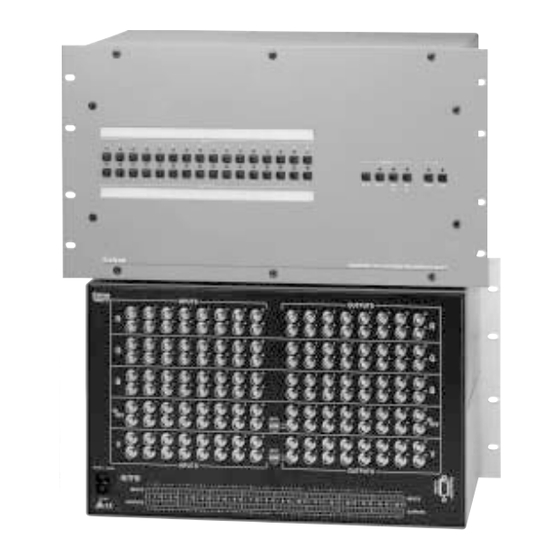
All connectors are on the rear panel. Figure 4 shows the CrossPoint Plus 128HVA. The CrossPoint Plus 84, 88, and 124 are housed in the same 3U enclosure, but have fewer input and/or output connectors to accommodate the different matrix sizes each provides. -
Page 15: Video Input And Output Connections
Video input and output connections All video input and output connections to the CrossPoint Plus switchers are made with female BNC connectors. Some types of video output devices do not have BNC video output connectors. For these cases, a suitable cable or connector adapter is necessary between the device output connector and the BNC input connector of the CrossPoint Plus. -
Page 16: Rs-232/422 Connection
Installation, cont’d Sleeve Tip (Left) Sleeve (Gnd) Ring (Right) Tip (Signal) Tip (Left) Sleeve (Gnd) Sleeve (Gnd) Unbalanced Mono Unbalanced Stereo Figure 7 — Phono audio connectors Connections for audio outputs — These 3.5 mm, 5-pole captive screw connectors output the selected unamplified, line level audio. Connect audio devices, such as an audio amplifier or powered speakers. - Page 17 INPUTS 1 2 4 INPUTS 1 2 4 INPUTS OUTPUTS Figure 9 — Rear panel view, CrossPoint Plus 84HV INPUTS 1 2 4 INPUTS 1 2 4 INPUTS OUTPUTS Figure 10 — Rear panel view, CrossPoint Plus 84HVA INPUTS 1 2 4 INPUTS 1 2 4 INPUTS...
- Page 18 Installation, cont’d INPUTS 1 2 4 INPUTS 1 2 4 INPUTS OUTPUTS Figure 14 — Rear panel view, CrossPoint Plus 124HVA INPUTS 1 2 4 INPUTS 1 2 4 INPUTS OUTPUTS Figure 15 — Rear panel view, CrossPoint Plus 128HV 1 3 5 7 1 3 5 7 Figure 16 —...
- Page 19 1 3 5 7 1 3 5 7 Figure 17 — Rear panel view, CrossPoint Plus 168HVA 1 3 5 7 1 3 5 7 Figure 18 — Rear panel view, CrossPoint Plus 1616HV CrossPoint Plus Matrix Switchers • Installation...
- Page 20 Installation, cont’d CrossPoint Plus Matrix Switchers • Installation...
-
Page 21: Chapter 3 • Operation
CrossPoint Plus Matrix Switchers Chapter Three Operation Front Panel Controls and Indicators Front Panel Operations Rear Panel Controls Worksheets... -
Page 22: Front Panel Controls And Indicators
While the number of inputs and outputs varies depending on the size of the matrix, there are only two front panel arrangements. The CrossPoint Plus 84, 88, 124, and 128 have 12 input buttons and 8 output buttons (figure 19). The CrossPoint Plus 168 and 1616 have 16 input buttons and 16 output buttons (figure 20). -
Page 23: Input Buttons, Output Buttons, And Leds
When a preset is retrieved from memory, it becomes the current configuration. One preset can be assigned to each input button. (On CrossPoint Plus 84, 88, 124, and 128 models, presets 13 through 16 can only be stored and retrieved via the RS-232 link.) -
Page 24: I/O Controls
Operation, cont’d As a secondary function on HVA models, the Esc button increments the audio level of the selected input. In audio adjust mode, the Esc LED indicates a positive (+) gain value. A more detailed explanation of audio level adjustment is included in “Viewing and adjusting the input audio level (HVA models only)”... -
Page 25: Front Panel Operations
Front Panel Operations The following paragraphs detail the power-up process and then provide sample procedures for creating ties, sets of ties, and configurations; changing a configuration; viewing ties, sets of ties, and configurations; saving a preset; recalling a preset; and viewing and adjusting the audio level. Power On all models, power is automatically applied when the power cord is connected to an AC source. -
Page 26: Creating A Configuration
Operation, cont’d The I/O groups can be set up only by using the RS-232 port and either the SIS or the Windows control program. Ties between groups (an input in group 1 tied to an output in group 2) can be created under RS-232 control. Presets can also be created under RS-232 control that tie inputs and outputs across group boundaries. -
Page 27: Example 1: Create A Set Of Video And Audio Ties
If the input button for a grouped input is pressed, and then the output button for an output in a different group is pressed, the associated output LED blinks twice and goes out to indicate that output cannot be tied to the input. -
Page 28: Example 3: Remove A Tie From A Set Of Video And Audio Ties
Operation, cont’d LED key: = off, = on, = blinking, = on for 2 seconds, then off RGBHV INPUTS CONTROL ENTER PRESET VIEW RGBHV AUDIO OUTPUTS ENTER Figure 24 — Example 2: Adding a video tie Press and release the Enter button. The input and output LEDs turn off. The current configuration is now defined as video input 5 tied to video output 1, output 3, output 4, and output 8;... -
Page 29: Viewing A Configuration
LED key: = off, = on, = on for 2 seconds, then off INPUTS AUDIO CONTROL ENTER PRESET VIEW RGBHV AUDIO OUTPUTS ENTER Figure 26 — Example 3d: Removing an audio tie Press and release the Enter button. The input and output LEDs turn off. The current configuration is now defined as video input 5 tied to video output 1, output 3, output 4, and output 8;... -
Page 30: Example 4: View Video And Audio, Audio Only, And Video Only Ties
Operation, cont’d Example 4: View video and audio, audio-only, and video-only ties See figure 27, figure 28, figure 29, and figure 30 and the following steps for an example of viewing the video and audio, audio-only, and video-only ties in the current configuration. -
Page 31: Using Presets
Each CrossPoint Plus switcher has as many presets available from the front panel as input buttons. On the CrossPoint Plus 84, 88, 124, and 128, the extra presets can be saved or stored via the RS-232 link only. -
Page 32: Example 5: Save A Preset
Operation, cont’d The current configuration and all presets are stored in non-volatile memory. When power is removed and restored, the current configuration is still active and all presets are retained. When a preset is recalled, it replaces the current configuration, which is lost unless it is also stored as a preset. -
Page 33: Viewing And Adjusting The Input Audio Level (Hva Models Only)
LEDs. The polarity is indicated by either the Esc ( ) or View ( ) LED blinking. On the CrossPoint Plus 84, 88, 124, and 128, each output LED indicates 1dB when blinking and 2dB when lit. On the CrossPoint Plus 168 and 1616, each output LED indicates 1dB when lit. - Page 34 INPUTS AUDIO CONTROL ENTER PRESET VIEW RGBHV AUDIO OUTPUTS +8dB Figure 33 — Example 7: Viewing the audio level, CrossPoint Plus 84, 88, 124, and 128 LED key: = off (value 0dB, = blinking, = on (value 1dB) TROL INPUTS...
-
Page 35: Executive Mode (Front Panel Security Lockout)
ENTER PRESET VIEW RGBHV AUDIO OUTPUTS -1dB (9 times) VIEW Figure 35 — Example 7d: Adjusting the audio level, CrossPoint Plus 84, 88, 124, and 128 LED key: = off (value 0dB, = blinking, = on (value 1dB) TROL INPUTS... -
Page 36: Rear Panel Controls
1, 3, 5, and 7 on the CrossPoint Plus 168 and 1616 models and inputs 1 through 4 (figure 37) on the CrossPoint Plus 84, 88, 124, and 128 models. The switches provide a way to condition non-TTL sync levels greater than 5Vp-p, enabling the sync to be properly passed from input to selected output(s). -
Page 37: Worksheet Example 2: Drawing Ties
Input sources Output destinations Preset # Title: Video: Audio: Fill in the preset number and use colors, or dashes, etc. to make connecting lines. Indicate if the configuration is for Video, Audio, or both. Figure 38 — Worksheet example 1: System equipment Worksheet example 2: Drawing ties Figure 39 continues from worksheet example 1 by showing the video and audio ties that make up the configuration of preset 3, a solid ink line shows video ties, and a... -
Page 38: Worksheet Example 3: Test Configuration
Operation, cont’d Worksheet example 3: Test configuration The A/V system in our fictional organization needs to be fine tuned on a regular basis. Figure 40 shows a typical test configuration, with an Extron video test generator (input 12) generating a test pattern to all monitors (outputs 1, 2, 3, 4, and 8). -
Page 39: Matrix Switchers Configuration Worksheet
Input sources Output destinations Preset # Title: Video: Audio: Fill in the preset number and use colors, or dashes, etc. to make connecting lines. Indicate if the configuration is for video, audio, or both. Matrix Switchers Configuration Worksheet... - Page 40 Operation, cont’d 3-20 CrossPoint Plus Matrix Switchers • Operation...
-
Page 41: Chapter 4 • Programmer's Guide
CrossPoint Plus Matrix Switchers Chapter Four Programmer’s Guide Host-to-Switcher Instructions Switcher-Initiated Messages Switcher Error Responses Using the Command/Response Table Command/Response Table... -
Page 42: Host-To-Switcher Instructions
The switcher-initiated messages are listed below (underlined). (C) Copyright 2001, Extron Electronics “CrossPoint/Mav/Matrix”, Vx.xx The copyright message is initiated by the switcher when it is first powered on. Vx.xx is the firmware version number. -
Page 43: Switcher Error Responses
RAM Test Failed ROM Checksum Failed EEPROM Reset (Presets/Attenuators) Serial EEPROM Reset (Current Settings) Invalid Jumpers If an error occurs during power-up, the switcher initiates one or more of the messages listed above. All Configuration Memory Cleared The memory cleared message is initiated by the switcher when a system reset has occurred. -
Page 44: Command/Response Table
= Carriage return (no line feed) • = space = Input number 01 – 08 (CrossPoint Plus 84, 88); Input and output numbers in 01 – 12 (CrossPoint Plus 124, 128); commands may be entered as either 1-digit or 2-digit 01 –... - Page 45 Command/response table for SIS commands (Cont’d) Command ASCII Command Response Additional description (host to switcher) (switcher to host) List all sync (DSVP) Input•Horz.•Vert. •• • thru •• • Example: Input•Horz.•Vert. 01••031.50•060.00 Input 1 (H) 31.5 kHz (V) 60 Hz thru thru 16••031.50•060.00 Input 16 (H) 31.5 kHz (V) 60 Hz.
- Page 46 Programmer’s Guide, cont’d Command/response table for SIS commands (Cont’d) Command ASCII Command Response Additional description (host to switcher) (switcher to host) Start direct write of global presets Write Preset Ready Allows direct entry of presets. {Tie commands} {Define ties for preset.} End direct write of global presets End Write Preset Saves directly written presets.
- Page 47 Command/response table for SIS commands (Cont’d) Command ASCII Command Response Additional description (host to switcher) (switcher to host) View preset configuration •(16 total)•Vid• •(16 total)•Aud Example Preset #0 is current configuration. 08•08•08•08•14•09•11•16•08•01•01•01•08•08•08•08•Vid•05•05•05•05•14•09•11•16•08•01•01•01•05•05•05•05•Aud Each position listed in the response is an input, left = input 1, right= input 16. The number in each position is the output tied to the input represented by that position.
- Page 48 Programmer’s Guide, cont’d CrossPoint Plus Matrix Switchers • Programmer’s Guide...
-
Page 49: Chapter 5 • Matrix Software
CrossPoint Plus Matrix Switchers Chapter Five Matrix Software Matrix Switchers Control Program Button-Label Generator... -
Page 50: Matrix Switchers Control Program
By default, the Windows installation creates a C:\MTRX directory, and it places two icons (Matrix Switcher+ Control Program and Matrix Switcher+ Help) into a group or folder named “Extron Electronics”. The program was designed to control most Extron matrix switchers, but its operation is limited to the features and configuration of your CrossPoint Plus Series switcher. -
Page 51: Windows Buttons
Figure 42 — Extron Matrix Switcher+ Control Program window (blank) Figure 43 — Sample program window (complete) To make the control program easier to use, assign a device icon to each input and output. Click on a box that represents an input or output, and drag the desired icon onto the box from the icon palette that appears. -
Page 52: Windows Menus
Matrix Software, cont’d Executive mode — Allows you to lock out front panel operations, except for the view-only mode functions Presets menu — Displays a list of up to 16 presets. You can select a preset from the list to display it in the window. Go —... -
Page 53: Using Emulation Mode
For information about program features, you can access the help program in any of the following ways: • From the Extron Electronics program folder or group, double-click on the Matrix Switcher Help icon (shown at left). • From within the Matrix Switcher Control Program, click on the Help menu on the main screen. -
Page 54: Using The Software
Matrix Software, cont’d Using the software To run the Button-Label Generator program, double-click on the Button-Label Generator icon (shown at left) in the Extron Electronics group or folder, and click OK when prompted. The Extron’s Button-Label Generator window appears (figure 44). -
Page 55: Appendix A • Specifications
CrossPoint Plus Matrix Switchers A ppendix A Specifications Specifications Part Numbers... - Page 56 Specifications Specifications, cont’d Video Routing .......... 84 series ....8 x 4 matrix 88 series ....8 x 8 matrix 124 series ....12 x 4 matrix 128 series ....12 x 8 matrix 168 series ....16 x 8 matrix 1616 series ....
- Page 57 Audio— audio models only Routing .......... 84 series ....8 x 4 stereo matrix 88 series ....8 x 8 stereo matrix 124 series ....12 x 4 stereo matrix 128 series ....12 x 8 stereo matrix 168 series ....16 x 8 stereo matrix 1616 series ....
-
Page 58: Crosspoint Plus Part Numbers
Specifications, cont’d Enclosure dimensions 84/88/124/128 series ..5.25" H x 17.0" W x 9.5" D (excluding connectors) 13.3 cm H x 43.2 cm W x 24.1 cm D 168/1616 series ....10.5" H x 17.0" W x 10.1" D 26.7 cm H x 43.2 cm W x 25.7 cm D Shipping weight 84/88/124/128 series .. - Page 59 Bulk cable Extron Part Part # Super High Resolution Cable SHR-1 bulk , 500’ 22-098-02 SHR-1 bulk , 1000’ 22-098-03 SHR-4 bulk , 500’ 22-099-02 SHR-5 bulk , 500’ 22-100-02 SHR male crimp connectors, qty. 50 100-075-51 BNC-4 Mini HR Cable BNC-4 Mini HR bulk, 500’...
- Page 60 Specifications, cont’d Extron Part Part # BNC-5 Mini HR Cable BNC-5-25’ MHR (25 feet/7.5 meters) 26-260-03 BNC-5-50’ MHR (50 feet/15.0 meters) 26-260-04 BNC-5-75’ MHR (75 feet/23.0 meters) 26-260-16 BNC-5-100’ MHR (100 feet/30.0 meters) 26-260-05 BNC-5-150’ MHR (150 feet/45.0 meters) 26-260-12 BNC-5-200’...
-
Page 61: Appendix B • Reference Information
CrossPoint Plus Matrix Switchers A ppendix B Reference Information Hardware Upgrades Button Labels... -
Page 62: Hardware Upgrades
Before you can perform any of the hardware upgrade procedures, you must open the switcher. The interior of the CrossPoint Plus 84, 88, 124, and 188 switchers is accessed by removing the top cover. The interior of the CrossPoint Plus 168 and 1616 is accessed by removing the front cover. -
Page 63: Opening The Crosspoint Plus 168 And 1616
Self-latching receptacle Place the top cover (CrossPoint Plus 84, 88, 124, and 128) and/or front cover (all models) in place and replace all the screws removed in “Opening the switcher” on page B-2. -
Page 64: Swapping The Serial Ports
Reference Information, cont’d Swapping the serial ports The CrossPoint Plus switchers are factory configured for RS-232 use. If you want to use RS-422 and the switcher is configured for RS-232, or if you want to use RS-232 and the switcher is configured for RS-422, do the following: Follow the appropriate instructions in “Opening the Switcher”... - Page 65 To replace the firmware, do the following: Follow the appropriate instructions in “Opening the Switcher” on page B-2 to gain access to the interior of your switcher, including the instructions for removing the front panel. Locate the RS-232/RS-422 ribbon cable that connects the front panel board to the rear panel RS-232/422 port (figure 47).
-
Page 66: Replacing The Ac Fuse (Crosspoint Plus 84, 88, 124, And 128 Only
The AC fuse on the power supply board is a user-replaceable component of the CrossPoint Plus 84, 88, 124, and 128. To replace the AC fuse, do the following: Follow the instructions in “Opening the CrossPoint Plus 84, 88, 124, and 128”... - Page 67 CrossPoint Plus Matrix Switchers • Reference Information...
- Page 68 Reference Information, cont’d CrossPoint Plus Matrix Switchers • Reference Information...
Need help?
Do you have a question about the CrossPoint Plus 84 and is the answer not in the manual?
Questions and answers