Advertisement
Quick Links
XTP II CrossPoint Series • Setup Guide
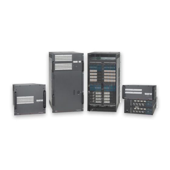
The XTP II CrossPoint Series matrix switchers route multiple signals between multiple local and remote sources and display
devices. This guide provides instructions for an experienced installer to install and connect any XTP II CrossPoint matrix switcher.
The different matrix switcher models share the same basic features
but they may be arranged differently.
•
XTP II CrossPoint 1600 — Supports up to four input and four
output boards in horizontal slots.
•
XTP II CrossPoint 3200 — Supports up to eight input and eight
output boards in vertical slots.
•
XTP II CrossPoint 6400 — Supports up to 16 input and 16
output boards in vertical slots.
Figure 1 shows the rear panel features of an XTP II CrossPoint 3200
matrix switcher but they apply to the other matrix switcher models.
Board Space
Input board space
A
Output board space
B
See "Board and Blank
Plate Installation" below
for details.
Installation
Board and Blank Plate Installation
Changing the boards changes the configuration of the matrix switcher. All boards are hot-swappable and can be installed without
removing power to the matrix switcher. Ensure a board or blank plate is installed in every slot (see figure 1,
ATTENTION:
Do not touch the electronic components or the connectors on the backplane or on the circuit
boards without being electrically grounded. Handle circuit boards by their edges only.
Removal
For boards, disconnect connected cables.
1.
Loosen the two knobs on the board or blank plate until the screws
2.
attaching the board are separated from the enclosure.
For boards, gently pull the knobs away from the enclosure to
3.
dislodge the board from the enclosure.
Slide the board or pull the plate out of the slot. Place boards on
4.
an anti-static surface or in an anti-static container.
Installation
If another board or blank plate interferes with the installation of a
1.
new board, remove it (see Removal).
For boards, slide the board in the slot along the guides and firmly
2.
push it into the enclosure so the panel is flush with the enclosure.
Tighten the two knobs on each end of the board or blank plate to
3.
secure it to the enclosure.
Enclosure Features
RS-232 and RS-422 connector
C
Ethernet LAN connector
D
Reset button and LED
E
AC power connector
F
See
Rear Panel Features
on the next
page for details.
A
XTP
CROSSPOINT 3200
INPUTS
1-4
5-8
9-12
13-16
17-20
21-24
25-28
REMOTE
C
D
LAN
E
RESET
F
DISCONNECT POWER
CORD BEFORE
SERVICING
XTP II CrossPoint 3200
Figure 1.
XTP II CrossPoint Matrix Switcher
Rear Panel Features
IN
IN
IN
IN
IN
IN
IN
IN
TE
O
RE
MO
/RS
422
U
RS
232
T
I
P
N
U
P
T
S
U
T
S
LIN
K
N
LA
T
AC
SE
T
RE
X
MA
--A
-24
0V
100
z
60H
50-
R
T PO
WE
E
NN
EC
OR
CO
RD
BEF
ING
DIS
SER
CO
VIC
XTP II CrossPoint 3200
B
OUTPUTS
29-32
1-4
5-8
9-12
13-16
17-20
21-24
25-28
29-32
1
5
9 13 17 21 25 29
4
8 12 16 20 24 28 32
O
I
U
N
T
P
P
U
U
T
T
S
S
1
5
9 13 17 21 25
29
4
8 12 16 20 24 28 32
and
).
A
B
Align with
Plastic Guides
O U
T
T
O U
O U
T
T
O U
O U
T
T
O U
O U
T
Knobs
1
Advertisement

Related Manuals for Extron electronics XTP II CrossPoint Series


Summary of Contents for Extron electronics XTP II CrossPoint Series
- Page 1 XTP II CrossPoint Series • Setup Guide The XTP II CrossPoint Series matrix switchers route multiple signals between multiple local and remote sources and display devices. This guide provides instructions for an experienced installer to install and connect any XTP II CrossPoint matrix switcher.
- Page 2 XTP II CrossPoint Series • Setup Guide (Continued) Mounting Use screws on each side of the matrix switcher to attach the front panel to a rack (see the XTP II CrossPoint Series User Guide at www.extron.com for more mounting information).
- Page 3 Input connectors Input boards for local sources may include the following connectors: HDMI input connectors — Connect a digital video source to a female HDMI input connector. It can accept HDMI, DVI (with • an appropriate adapter), or dual mode DisplayPort video signals. NOTE: Use an Extron LockIt Lacing Bracket to secure HDMI cables to the rear panel connectors.
- Page 4 Connect the PC to the front panel USB configuration connector, a network connected tot he rear panel Ethernet LAN connector, or rear panel RS-232 and RS-422 connector. For a list of SIS commands and expected responses, see the XTP II CrossPoint Series User Guide at www.extron.com. Internal Web Pages The internal web pages allow configuration and control of the matrix switcher through a network.
Need help?
Do you have a question about the XTP II CrossPoint Series and is the answer not in the manual?
Questions and answers