Table of Contents
Advertisement
Quick Links
Download this manual
See also:
Installation Manual
Advertisement
Table of Contents

Subscribe to Our Youtube Channel
Related Manuals for DFI OPS100-SH


Summary of Contents for DFI OPS100-SH
- Page 1 OPS100-SH User’s Manual A44900714 Chapter 1 Introduction www.dfi.com...
-
Page 2: Copyright
Product names or trademarks appearing in this manual are for identification purpose only and Shielded interface cables must be used in order to comply with the emission limits. are the properties of the respective owners. Chapter 1 Introduction www.dfi.com... -
Page 3: Table Of Contents
I/O Ports (OPS-DB) ..............18 Trademarks ............2 12~19V DC-in (OPS-DB) ................18 Display Interfaces (OPS100-SH and OPS-DB) ..........19 FCC and DOC Statement on Class A ....2 USB Ports (OPS100-SH and OPS-DB) ............20 COM Port (OPS100-SH and OPS-DB) ............21 About this Manual ..........4... -
Page 4: About This Manual
After installation or servicing, cover the system chassis before plugging the power cord. Battery: • Danger of explosion if battery incorrectly replaced. • Replace only with the same or equivalent type recommend by the manufacturer. • Dispose of used batteries according to local ordinance. Chapter 1 Introduction www.dfi.com... -
Page 5: Safety Precautions
• Unplug the power cord before removing the system chassis cover for installation or servic- ing. After installation or servicing, cover the system chassis before plugging the power cord. • 1 OPS100-SH system unit • 1 CD disk includes: Drivers and Manual •... -
Page 6: Chapter 1 - Introduction
USB 3.0 USB 2.0 Power Button Notes: 1. Throughout this guide the OPS100-SH may be referred to as the OPS+ Module. 2. The OPS-DB (referred to as the Docking Board) is an expansion dock, which provides additional I/O connectivity. DP(B) -
Page 7: Specifications
2 x Wi-Fi Module Antenna Holes • Rear Panel The JAE TX25A-80P connector: The Hirose FX18-60S connector: 1 x HDMI 2.0 1 x DP 1.2 1 x DP 1.2 2 x USB 2.0 1 x USB 3.0 1 x 12~19V DC-in Chapter 1 Introduction www.dfi.com... -
Page 8: Getting To Know The Ops100-Sh
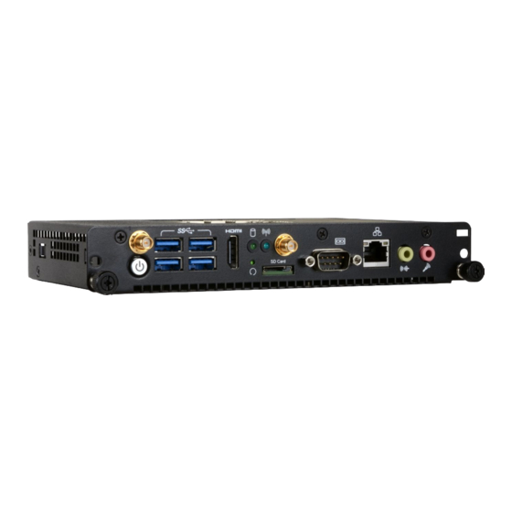
Chapter 1 Getting to Know the OPS100-SH Front View Rear View Antenna Hole HDD LED HDMI-in HRS FX18 JAE TX25A Antenna Hole USB 3.0 Wireless LED Power Button Reset Button Mic-in microSD Card Line-out Power Button with LED (Green) Press this button to power on or power off the system. -
Page 9: Mechanical Dimensions
119.00 56.43 34.15 20.00 17.00 15.74 Right View 10.97 Left View Top View 10.40 2-R2.25 2.95 91.50 0.00 1.50 2-R2.25 7.00 3.00 14.50 5.00 5.00 23.00 192.00 4.50 4.50 14.50 Front View Unit: mm Unit: mm Chapter 1 Introduction www.dfi.com... -
Page 10: Chapter 2 - Getting Started
Installing the Drivers The system package includes a CD disk. The CD includes drivers that must be installed to pro- vide the best system performance. Refer to the Supported Software chapter for instructions on installing the drivers. Chapter 2 Getting Started www.dfi.com... -
Page 11: Chapter 3 - Installing The Devices
Chapter 3 Chapter 3 - Installing the Devices Installing the OPS100-SH into a Display Secure the module by attaching two screws on the front panel. Observe the following precautions and guidelines before starting any installation procedures described in this chapter: Make sure the system and all other peripheral devices connected to it have been powered- off. -
Page 12: Removing The Chassis Cover
Chapter 3 Removing the Chassis Cover Installing the OPS100-SH into the OPS-DB The OPS+ Module has an accompanying Docking Board and allows it to serve as a standalone Observe the precautions at the beginning of this chapter before proceeding with the computing system. -
Page 13: Installing A Sodimm
Notes: The system supports dual-channel configuration. To enable dual-channel, populate both SODIMM sockets. M.2 SSD connector The SODIMM sockets can only accept DDR4 memory modules. Please do not install other types of memory modules. Chapter 3 Installing the Devices www.dfi.com... -
Page 14: Installing A Wi-Fi Module
Secure the card to the riser screw on the board using the screw shipped with the M.2 module. Secure the card to the riser screw on the board using the screw shipped with the M.2 module. M.2 wireless module M.2 SSD card Chapter 3 Installing the Devices www.dfi.com... -
Page 15: Chapter 4 - Board Layout And Jumper Settings
Chapter 4 Chapter 4 - Board Layout and Jumper Settings OPS-DB OPS100-SH Clear CMOS Data USB Power Select COM 1 HRS FX18-60P JAE TX24A-80R MicroSD Clear CMOS USB 3.0 USB 3.0 (J23) Power-on Battery (J3) Buzzer SYS Fan (J3) GPIO (J4) -
Page 16: At/Atx Mode Select
AT power scheme. With the AT mode, you need to manually turn off the system with the power switch; whereas in the ATX mode, the system can be pow- ered off using the shut-down function provided by the OS. Chapter 4 Jumper Settings www.dfi.com... -
Page 17: Chapter 5 - Ports And Connectors
• HDMI-in port • HDD LED (green) • Wireless LED (blue) • Reset button • microSD card slot • COM (RS232) serial port • LAN port • Mic-in and line-out jack Chapter 2 Hardware Installation www.dfi.com Chapter 5 Ports and Connectors... -
Page 18: I/O Ports (Ops-Db)
DC-in jack DC-in Connect a DC power cord to this DC-in jack. Using a voltage more than the recommended range may fail to boot the system or damage the system board. Chapter 2 Hardware Installation www.dfi.com Chapter 5 Ports and Connectors... -
Page 19: Display Interfaces (Ops100-Sh And Ops-Db)
Chapter 5 Display Interfaces (OPS100-SH and OPS-DB) Display Interfaces (OPS100-SH) Display Interfaces (OPS-DB) HRS FX18-60P JAE TX24A-80R HDMI-in SYS Fan (J3) GPIO (J4) I2C (J6) PCIE1(PCIe 3.0 x4) COM 1 Line_out MicroSD Clear (J5) CMOS USB 3.0 USB 3.0 (J23) -
Page 20: Usb Ports (Ops100-Sh And Ops-Db)
The Docking Board is equipped with one USB 3.0 and two USB 2.0 ports. The USB 3.0 can The OPS100-SH is equipped with four USB 3.0 port. USB devices allow data exchange between transfer data up to 5 Gbps whereas the USB 2.0 can transfer data up to 480Mbps. -
Page 21: Com Port (Ops100-Sh And Ops-Db)
Chapter 5 COM Port (OPS100-SH and OPS-DB) COM Port (OPS-DB) COM Port (OPS100-SH) 2 3 4 5 HRS FX18-60P JAE TX24A-80R 6 7 8 9 SYS Fan (J3) GPIO (J4) I2C (J6) PCIE1(PCIe 3.0 x4) COM 1 Line_out (J5) USB PWR... -
Page 22: Rj45 Lan Port (Ops100-Sh)
Chapter 5 RJ45 LAN Port (OPS100-SH) Audio (OPS100-SH) Speed LED ACT/Link LED LAN 1 Mic-in Line-out COM 1 MicroSD Clear COM 1 CMOS USB 3.0 USB 3.0 (J23) Power-on MicroSD Clear CMOS Battery (J3) USB 3.0 USB 3.0 (J23) Power-on... -
Page 23: Storage And Communication Expansion Slots
Chapter 5 Storage and Communication Expansion Slots M.2 Slots (OPS100-SH) (OPS100-SH and OPS-DB) The M.2 card slots on the back side of the system board are used to install M.2 (NGFF) mod- ules. The M.2 Type 2280 (M Key) slot can be inserted with either an mSATA SSD card or a PCIe NVMe card with the form factor of M.2 22x80 mm. -
Page 24: Internal I/O Connectors
Chapter 5 Internal I/O Connectors Line-out Connector (OPS-DB) LPC Connector (OPS100-SH) HRS FX18-60P JAE TX24A-80R COM 1 MicroSD Clear CMOS USB 3.0 USB 3.0 (J23) Power-on SYS Fan (J3) GPIO (J4) Battery (J3) I2C (J6) PCIE1(PCIe 3.0 x4) Line_out (J5) -
Page 25: Fan Connector (Ops100-Sh And Ops-Db)
Chapter 5 FAN Connector (OPS100-SH and OPS-DB) FAN Connector (OPS100-SH) FAN Connector (OPS-DB) COM 1 HRS FX18-60P MicroSD JAE TX24A-80R Clear CMOS USB 3.0 USB 3.0 (J23) Power-on Battery (J3) Buzzer Intel SYS Fan (J3) GPIO (J4) I2C (J6) PCIE1(PCIe 3.0 x4) -
Page 26: Gpio Connector (Ops-Db)
The I2C bus is a multi-device and serial communication bus. It can be used to provide short- distance communication among low-speed peripheral ICs. Chapter 2 Hardware Installation www.dfi.com Chapter 5 Ports and Connectors... -
Page 27: Standby Power Led (Ops100-Sh)
Chapter 5 Standby Power LED (OPS100-SH) Battery (OPS100-SH) COM 1 COM 1 MicroSD Clear MicroSD Clear CMOS USB 3.0 USB 3.0 CMOS USB 3.0 USB 3.0 (J23) Power-on (J23) Power-on Battery (J3) Ground Battery (J3) Battery Buzzer Buzzer Intel Intel... -
Page 28: The Tx25A-80P Connector (Ops100-Sh)
TMDS0_0- DVI-D USB_PN2 Audio: left and right Channel USB: 1*USB 3.0 and 3*USB 2.0 Ground Ground Control and Sensors: 1*UART and Consumer Electronics Control (CEC, note that the OPS100-SH TMDS0_CLK+ DVI-D StdA_SSTX+ USB3.0 does not support this function) TMDS0_CLK- DVI-D StdA_SSTX- USB3.0... -
Page 29: Signal Description
DDP_0N Consumer Electronics Control for Proof of Play/Display initiative. Can also DDP_1P be used for display panel status detection and other control functions. DDP_1N *Note that the OPS100-SH does not support the CEC function. DDP_2P DDP_2N DDP_3P DDP_3N Chapter 2 Hardware Installation www.dfi.com... - Page 30 Reserved 41, 42, 43, 44, RSVD These pins are RESERVED for future expansion and shall be left as No 45, 46, 47, 48, Connect(NC) Chapter 2 Hardware Installation www.dfi.com Chapter 5 Ports and Connectors...
-
Page 31: The Fx18-60S Connector (Ops100-Sh)
Chapter 5 The FX18-60S Connector (OPS100-SH) Ground PCIE-TXN3 PCIe The right angle mate plug connector (p/n: Hirose FX18-60S-0.8SH) should be mated with the receptacle connector (p/n: Hirose FX18-60P-0.8SH); together, they provide interfacing for the PCIE-RXP3 PCIe Ground following functions: PCIE-RXN3... -
Page 32: Signal Description
PCI Express Differential Transmit Pair Signals PCIE-TXN3 PCIE-TXP2 PCIE-TXN2 PCIE-TXP1 PCIE-TXN1 PCIE-TXP0 PCIE-TXN0 PCI_E_WAKE Wake Indicator from PCI-E PHY Device PCIE_CLK_P 100-MHz PCIe 3.0 specification compliant differential output clocks to PCIe devices PCIE_CLK_N Chapter 2 Hardware Installation www.dfi.com Chapter 5 Ports and Connectors... -
Page 33: Chapter 6 - Bios Setup
To display the submenu, move the highlight to you respond, restart the system or press the “Reset” button. You may also restart the system that field and press <Enter>. by pressing the <Ctrl> <Alt> and <Del> keys simultaneously. Chapter 6 BIOS Setup www.dfi.com... -
Page 34: Main
Minute displays minutes from 00 to 59. Second displays seconds from 00 to 59. System Date The date format is <month>, <date>, <year>. Month displays the month, from January to December. Date displays the date, from 1 to 31. Year displays the year, from 1980 to 2099. Chapter 6 BIOS Setup www.dfi.com... - Page 35 Real-time clock battery. Specify the wake up time of the day below: <hour>, formance of operating systems and software that are optimized for hyper-threading <minute>, <second>. technology. Please check the software specifications to determine if enabling HT can be advantageous to the overall system performance. Chapter 6 BIOS Setup www.dfi.com...
- Page 36 CPU)->PCIe graphics devices->PCI graphics devices Note that this option is only shown if the “Boot type” is set to “Dual” or “UEFI”. Internal Graphics Device Enable, disable or automatically detect the internal graphics. Chapter 6 BIOS Setup www.dfi.com...
- Page 37 Control the detection of the high-definition audio devices. Disabled High-definition audio devices will be unconditionally disabled. Enabled High-definition audio devices will be unconditionally enabled. Auto High-definition audio devices will be enabled if present and disabled otherwise. Chapter 6 BIOS Setup www.dfi.com...
- Page 38 PCIe NVMe SSD is used instead of an mSATA SSD, this option will not be Enable this item for operating systems that do not support xHCI Hand-off. The XHCI shown. ownership change will be claimed by the XHCI driver. Chapter 6 BIOS Setup www.dfi.com...
- Page 39 PCIe Speed Select the speed of the PCI Express root port: Auto, Gen1 (2.5 GT/s), Gen2 (5 GT/s) or Gen3 (8 GT/s). Hot Plug Enable or disable the hot plug function of the PCIe root port. Chapter 6 BIOS Setup www.dfi.com...
- Page 40 Management Engine firmware flashing when updating the BIOS. ® Intel AMT Support Enable or disable Intel Active Management Technology BIOS extension. ® Un-Configure ME Clears all ME related configurations without requiring a password on the next boot. Chapter 6 BIOS Setup www.dfi.com...
- Page 41 Enter or choose the serial port number for message output. The options are COM1 (0x3F8)/ COM2 (0x2F8). The default is 0x3F8. EFI Debug baud rate Enter or choose the baud rate for serial communication. The default is 115200. Chapter 6 BIOS Setup www.dfi.com...
- Page 42 Enter the duration (seconds) for the Ethernet’s ACT LED to blink to indicate its presence. NIC Configuration This screen configures the Ethernet controller. Select the link speed from the following options: Auto Negotiated, 10Mbps Half, 10Mbps Full, 100Mbps Half, and 100Mbps Full. Chapter 6 BIOS Setup www.dfi.com...
- Page 43 New Gateway addresses: Enter gateway addresses in the IPv6 format. Local DNS (Domain Name System) Servers: Enter DNS (Domain Name System) server IP New DNS addresses: Enter DNS (Domain Name System) server IP addresses in the IPv6 addresses in the IPv4 format. format. Chapter 6 BIOS Setup www.dfi.com...
- Page 44 Enable or disable the watchdog function. A counter will appear if you select to enable WDT. Input any value between 1 and 255. CPU Smart Fan Control Enable the CPU smart fan control to let the system dynamically adjust fan speeds ac- cording to CPU temperatures. Chapter 6 BIOS Setup www.dfi.com...
- Page 45 Parity: None, Even or Odd. Stop bits: 1 bit or 2 bits. Flow control: None, RTS/CTS or XON/XOFF This is the global setting for all of the designated serial ports for the console redirection function. Chapter 6 BIOS Setup www.dfi.com...
- Page 46 Chapter 6 MEBX Configuration The Manageability Engine BIOS Extension (MEBx) Setup allows you to set up Intel Active ® Management Technology (Intel AMT). For more information, please refer to Chapter 8. ® Chapter 6 BIOS Setup www.dfi.com...
-
Page 47: Security
• Enable: Enable and activate TPM. Clear TPM Remove all TPM ownership contents. Note: To enable the Intel ® TXT function on the system, please enable the activate the TPM function first. Chapter 6 BIOS Setup www.dfi.com... -
Page 48: Boot
Enable or disable Preboot eXecution Environment (PXE) boot to LAN. In the UEFI or Dual boot mode, this function can only be enabled if the Network Stack support is enabled. USB Boot Enable or disable booting to USB boot devices. Chapter 6 BIOS Setup www.dfi.com... -
Page 49: Exit
DSF file extension and can be used for restoration. Restore Setting from file Select this option to restore BIOS configuration settings from a USB drive. Note that this option will not be available if there aren’t any USB devices detected on the system. Chapter 6 BIOS Setup www.dfi.com... -
Page 50: Updating The Bios
EEPROM programmer has been burned and follow the Copyright(c) 2012 - 2017, Insyde Software Corp. All Rights Reserved. technical person's instructions to confirm that the MAC address should be burned Initializing Current BIOS Model name: OPS100-SH or not. New BIOS Model name: OPS100-SH Current BIOS version: B176.06A New BIOS version: B176.06A... -
Page 51: Chapter 7 - Supported Software
Insert the DVD into a DVD-ROM drive. The auto-run screen will appear. If the “Autorun” does not automatically start, please go directly to the root directory of the DVD and double-click “Setup”. For Windows 10 Chapter 7 Supported Software www.dfi.com... -
Page 52: Intel Chipset Software Installation Utility
Click “Next”. 4. Please wait while the instal- lation is in progress. 2. Read the license agreement, and then click “Yes”. 5. Click “Restart Now” to allow the new software installa- tion to take effect. Chapter 7 Supported Software www.dfi.com... - Page 53 2. Read the license agree- 5. Click “Yes, I want to restart ment, and then click “Yes”. this computer now”, and then click “Finish”. Restarting the system will allow the new software installation to take effect. Chapter 7 Supported Software www.dfi.com...
- Page 54 5. After the installation is complete, click “Finish”. 2. Click “I accept the terms in the license agreement” if you accept the agreement, and then click “Next”. 3. Select the program features you want installed, and then click “Next”. Chapter 7 Supported Software www.dfi.com...
- Page 55 1. Setup is ready to install the driver. Click “Next” to continue. 4. Please wait while the prod- uct is being installed. 2. Read the license agree- ment, and then click “Next”. 5. After the installation is complete, click “Finish”. Chapter 7 Supported Software www.dfi.com...
- Page 56 Click “Next” to continue. 4. Setup is currently installing the driver. After the installation is complete, click “Next”. 2. Read the license agreement, and then click “Yes”. 5. After the installation is complete, click “Finish”. Chapter 7 Supported Software www.dfi.com...
- Page 57 Click “I accept the terms in the “Finish”. License Agreement” if you agree with the terms in the agreement and then Restart the system to allow the new click “Next”. software installation to take effect. Chapter 7 Supported Software www.dfi.com...
- Page 58 5. Setup is now installing the driver. 3. Read the file information and then click “Next”. 4. Setup is ready to install the driver. 6. Click “Finish” to exit the setup. Click “Next” to begin the installation. Chapter 7 Supported Software www.dfi.com...
- Page 59 To install Bluetooth drivers, click “Bluetooth ” in the main menu. The Intel PROSet/ Wireless Tools Installation Wizard will start. Please follow the on-screen instructions to complete the installation. 2. Setup is now installing the driver. Chapter 7 Supported Software www.dfi.com...
-
Page 60: Chapter 8 - Intel Amt Settings
It protects the network from threats at the source by proactively blocking incoming threats, reactively containing infected clients before they impact the network, and proactively alerting when critical software agents are removed. 3. In the “Active Management Technology Support” menu, select “Enabled” for “Intel AMT Support”. Chapter 8 Intel AMT Settings www.dfi.com... - Page 61 Copyright(C) 2003-15 Intel Corporation. All Rights Reserved. MAIN MENU MEBx Login > Intel (R) ME General Settings > Intel (R) AMT Configuration MEBx Exit Intel(R) ME Password [↑↓] = Move Highlight [Enter] = Select Entry [Esc]= Exit Chapter 8 Intel AMT Settings www.dfi.com...
- Page 62 Intel(R) Management Engine BIOS Extension v11.0.0.0005/Intel(R) ME v11.0.0.1205 Copyright(C) 2003-15 Intel Corporation. All Rights Reserved. MAIN MENU > Intel (R) ME General Settings > Intel (R) AMT Configuration MEBx Exit [↑↓] = Move Highlight [Enter] = Select Entry [Esc]= Exit Chapter 8 Intel AMT Settings www.dfi.com...
- Page 63 > User Consent Password Policy <Anytime> > Network Setup Activate Network Access Unconfigure Network Access <Full Unprovision> > Remote Setup And Configuration > Power Control [↑↓] = Move Highlight [Enter] = Select Entry [Esc]= Exit Chapter 8 Intel AMT Settings www.dfi.com...
- Page 64 <Full Unprovi- Disabled sion> Enabled > Remote Setup And Configuration > Power Control [↑↓] = Move Highlight [Enter] = Select Entry [Esc]= Exit [↑↓] = Move Highlight [Enter] = Complete Entry [Esc]= Discard Changes Chapter 8 Intel AMT Settings www.dfi.com...
- Page 65 < Enabled> Storage Redirection <Enabled> KVM Feature Selection <Enabled> NONE Disabled Enabled [↑↓] = Move Highlight [Enter] = Complete Entry [Esc]= Discard Changes [↑↓] = Move Highlight [Enter] = Complete Entry [Esc]= Discard Changes Chapter 8 Intel AMT Settings www.dfi.com...
- Page 66 > Remote Setup And Configuration > Power Control Default Password Only During Stepup And Configuration Anytime [↑↓] = Move Highlight [Enter] = Select Entry [Esc]= Exit [↑↓] = Move Highlight [Enter] = Complete Entry [Esc]= Discard Changes Chapter 8 Intel AMT Settings www.dfi.com...
- Page 67 Shared/ Dedicated FQDN <Shared> Dynamic DNS Update <Disabled> Dynamic DNS Update <Disabled> Computer Domain Name Disabled Enabled [Enter] = Complete Entry [Esc]= Discard Changes [↑↓] = Move Highlight [Enter] = Complete Entry [Esc]= Discard Changes Chapter 8 Intel AMT Settings www.dfi.com...
- Page 68 Unconfigure Network Access > Remote Setup And Configuration Full Unprovision > Power Control [↑↓] = Move Highlight [Enter] = Complete Entry [Esc]= Discard Changes [↑↓] = Move Highlight [Enter] = Complete Entry [Esc]= Discard Changes Chapter 8 Intel AMT Settings www.dfi.com...
- Page 69 > RCFG > TLS PKI > TLS PKI Provisioning Mode: PKI Provisioning server address [↑↓] = Move Highlight [Enter] = Select Entry [Esc]= Exit [↑↓] = Move Highlight [Enter] = Select Entry [Esc]= Exit Chapter 8 Intel AMT Settings www.dfi.com...
- Page 70 PKI DNS Suffix > Manage Hashes This will activate Remote Condigura- tion. Continue: (Y/N) Disabled Enabled [↑↓] = Move Highlight [Enter] = Select Entry [Esc]= Exit [↑↓] = Move Highlight [Enter] = Select Entry [Esc]= Exit Chapter 8 Intel AMT Settings www.dfi.com...
- Page 71 Activate Network Access Unconfigure Network Access <Full Unprovision> > Remote Setup And Configuration > Power Control [↑↓] = Move Highlight [Enter] = Select Entry [Esc]= Exit [↑↓] = Move Highlight [Enter] = Select Entry [Esc]= Exit Chapter 8 Intel AMT Settings www.dfi.com...
- Page 72 This configurations are effective only after AMT provisioning has started Intel (R) ME ON in Host Sleep States <Mobile: ON in S0, ME Wake in S3, S4-5 (AC only)> Idle Timeout 65535 Timeout Value (1-65535) 65535 <ENTER> = Complete Entry [ESC]= Discard Changes Chapter 8 Intel AMT Settings www.dfi.com...
Need help?
Do you have a question about the OPS100-SH and is the answer not in the manual?
Questions and answers