Table of Contents
Advertisement
Quick Links
Advertisement
Table of Contents

Related Manuals for DFI DT122-BE


Summary of Contents for DFI DT122-BE
- Page 1 DT122-BE Desktop Box PC User’s Manual A38800532 Chapter 1 Introduction...
-
Page 2: Copyright
Copyright FCC and DOC Statement on Class A This publication contains information that is protected by copyright. No part of it may be re- This equipment has been tested and found to comply with the limits for a Class A digital produced in any form or by any means or used to make any transformation/adaptation without device, pursuant to Part 15 of the FCC rules. -
Page 3: Table Of Contents
Chassis Intrusion Connector ............... 31 Key Features ....................6 LPC Connector ..................32 Specifications ....................7 Standby Power LED ................... 32 Getting to Know the DT122-BE .............. 8 Battery ..................... 33 Mechanical Dimensions ................9 Motherboad Dimensions Chapter 6 - Mounting Options ................ -
Page 4: About This Manual
About this Manual Static Electricity Precautions An electronic file of this manual is included in the CD. To view the user’s manual in the CD, in- It is quite easy to inadvertently damage your PC, system board, components or devices even sert the CD into a CD-ROM drive. -
Page 5: Safety Precautions
• Unplug the power cord before removing the system chassis cover for installation or servic- ing. After installation or servicing, cover the system chassis before plugging the power cord. • 1 DT122-BE system unit • 1 HDD drive bay kit •... -
Page 6: Chapter 1 - Introduction
Chapter 1 Chapter 1 - Introduction Key Features Overview Model Name DT122-BE ® 2nd Generation AMD Embedded R-Series APU FP3 BGA Processor A77E Fusion Controller Hub Chipset ® 2 LAN ports 4 DP ports support DP++ Displays 4 USB 3.0 ports... -
Page 7: Specifications
Chapter 1 Specifications Processor System • CPU Environment • Temperature - 2nd Generation AMD ® Embedded R-Series APU FP3 BGA - Operating: 0 C~45 (28nm process technology) - Storage: -20 C~60 ® • Humidity : AMD RX-427BB, Quad Core, 4M Cache, 2.7GHz (3.6GHz), 35W ®... -
Page 8: Getting To Know The Dt122-Be
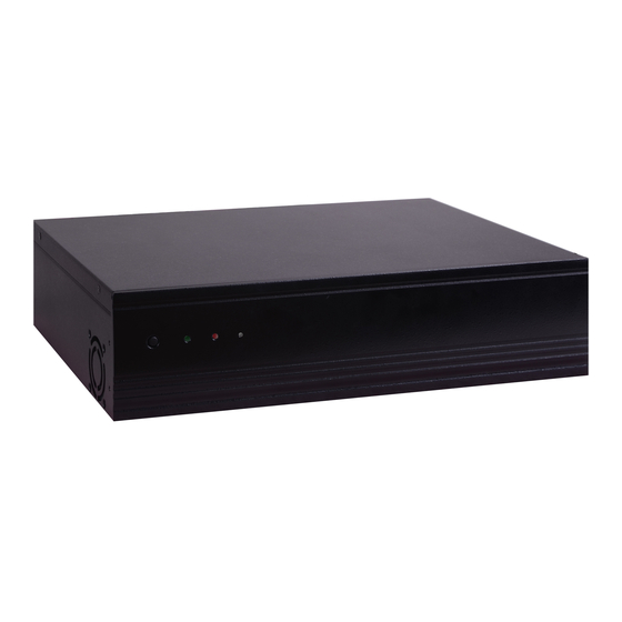
Chapter 1 Getting to Know the DT122-BE Front View Rear View LAN 1-2 DP 2-3 Reset Button DP 0-1 Line-in Power LED Power Button USB 3.0 Mic-in HDD LED USB 3.0 Line-out Power Button DP Ports Press to power-on or power-off the system. -
Page 9: Mechanical Dimensions
Chapter 1 Mechanical Dimensions Motherboard Dimensions 0.00 6.17 Rear View 19.49 36.23 41.25 43.64 61.23 71.71 89.60 92.43 Left View Right View 300.00 117.60 143.43 145.42 148.00 162.07 163.65 Front View 170.00 Chapter 1 Introduction www.dfi .com... -
Page 10: Chapter 2 - Getting Started
Chapter 2 Chapter 2 - Getting Started Preparing the System Before you start using the system, you need the following items: • SATA hard drive • AC power adapter • PS/2 or USB keyboard • PS/2 or USB mouse • CD-ROM drive (for installing software/drivers) •... -
Page 11: Chapter 3 - Installing Devices
Chapter 3 Chapter 3 - Installing Devices 5. The SODIMM sockets, Mini PCIe slot and SATA drive bay are readily accessible after removing the chassis cover. Removing the Chassis Cover 1. Make sure the system and all other peripheral devices connected to it have been powered-off. 2. -
Page 12: Installing The Sodimm Module
Chapter 3 3. Note how the module is keyed to the socket. Installing the SODIMM Module 1. There are two SODIMM sockets on the system board. Notch SODIMM sockets 2. Push the “ejector tabs” which are at the ends of the socket to the side. 4. -
Page 13: Installing The Mini Pcie Card
Chapter 3 Installing the Mini PCIe Card 3. Grasping the Mini PCIe card by its edges, align the card into the slot at an approximately 30 degrees angle. Apply fi rm even pressure to each end of the card until it slips down into the slot. -
Page 14: Installing A 2.5" Or 3.5" Sata Drive
Chapter 3 Installing a 2.5" or 3.5" SATA Drive 3. Align the mounting holes of the SATA drive with the mounting holes on the HDD bracket and then use the provided mounting screws to secure the drive in place. Installing a 2.5” SATA Drive Mounting screw 1. - Page 15 Chapter 3 4. Turn to the other side of the drive bay. Use the provided mounting screws from step 2 to 6. Connect the SATA data cable and SATA power cable to the connectors on the SATA drive. secure the SATA drive (with the HDD) onto the drive bay. Drive bay Mounting screw Mounting screw...
- Page 16 Chapter 3 lnstalling a 3.5" SATA Drive 4. Use the provided mounting screws to secure the SATA drive onto the drive bay. 1. Remove the 4 mounting screws that secure the drive bay to the system. Mounting screw Mounting screw Mounting screw Drive bay Drive bay...
-
Page 17: Installing The Pci Or Pcie X16 Expansion Card
Chapter 3 Installing the PCI or PCIe x16 Expansion Card Important: When inserting the riser card, please select a card within Bracket 175mm (as shown on the next picture). Mounting bracket and mounting screw 1. The PCIe x16 on the motherboard is used to insert a T200-1P or T200-1E riser card. To install the expansion card, you need to remove the mounting bracket and the mounting screw that secure the bracket to the chassis and then remove the bracket. - Page 18 Chapter 3 2. Insert the Expansion card with a bracket into the PCI or PCIe x16 slot that is on the riser card. Replace the screw you removed in step 1 to secure the bracket in place. Bracket Mounting bracket and mounting screw PCIe x16...
-
Page 19: Chapter 4 - Jumper Settings
Chapter 4 Chapter 4 - Jumper Settings Auto Power-on Select Clear CMOS Data JP15 1-2 On: Power-on via power button 1-2 On: (default) Normal (default) 2-3 On: 2-3 On: Power-on via AC power Clear CMOS Data If you encounter the following, JP15 is used to select the method of powering on the system. -
Page 20: Usb Power Select
Chapter 4 USB Power Select SATA DOM Power Select 2-3 On: 1-2 On: +5V +5V_standby (default) USB 3.0 0-1 USB 2.0 0-1/2-3 SATA 0 (JP8) (JP10) USB 3.0 2-3 (JP9) 1-2 On: +5V 1-2 On: GND (default) (default) USB 2.0 5 (JP11) 2-3 On: +5V_standby... -
Page 21: Com 1 Rs232/422/485 Select
Chapter 4 COM 1 RS232/422/485 Select COM 1 RS422 RS232 RS485 Full Duplex COM 1: RS232/422/485 3-4 On: RS422 5-6 On: RS485 1-2 On: RS232 Full Duplex (default) JP4 and JP5 1-3, 2-4 On: 3-5, 4-6 On: RS232 (default) RS422 Full Duplex/RS485 JP3, JP4 and JP5 allow you to configure the Serial COM port 1 to RS232, RS422 (Full Duplex) Note: or RS485. -
Page 22: Digital I/O Power Select
Chapter 4 Digital I/O Power Select Digital I/O Output State DIO 4-7 (JP14) JP12 1-2 On: +5V or +5V_standby (default) 1-2 On: +5V_standby DIO 0-3 (default) (JP13) 2-3 On: GND 2-3 On: +5V JP12 is used to select the power of DIO (Digital I/O) signal. Based on the power level of DIO (Digital I/O) selected on JP12, JP13 (DIO pin 0-3) and JP14 (DIO pin 4-7) are used to select the state of DIO output: pull high or pull low. -
Page 23: Mini Pcie Signal Select
Chapter 4 Mini PCIe Signal Select Mini PCIe Power Select 1-4-7-10, 2-5-8-11 On: 1-2 On: +3.3V_standby (Mini PCIe) PCIe (default) (default) 2-3 On: +3.3V (mSATA) 2-5-8-11, 3-6-9-12 On: mSATA JP7 is used to select the power supplied with the Mini PCIe. JP6 is used to select the Mini PCIe signal: PCIe or mSATA. -
Page 24: Chapter 5 - Ports And Connectors
Chapter 5 Chapter 5 - Ports and Connectors Graphics Interfaces Rear Panel I/O Ports The display ports consist of the followings: • 4 DP ports LAN 1-2 DP 2-3 DP 0-1 Line-in DP 1 DP 3 DP 0-1 Mic-in USB 3.0 Line-out USB 3.0 DP 2-3... -
Page 25: Rj45 Lan Ports
Chapter 5 RJ45 LAN Ports USB Ports LAN 1 LAN 2 USB 1 USB 3 LAN 1 USB 0 USB 2 USB 3.0 USB 3.0 USB 5 LAN 2 USB 2.0 USB 2-3 USB 0-1 Features ® • 1 Intel I210 PCI Express Gigabit Ethernet controller USB 2.0 •... -
Page 26: Audio
Chapter 5 Audio Driver Installation You may need to install the proper drivers in your system operation to use the USB device. Refer to your operating system’s manual or documentation for more information. Wake-On-USB Keyboard/Mouse The Wake-On-USB Keyboard/Mouse function allows you to use a USB keyboard or USB mouse to wake up a system from the S3 (STR - Suspend To RAM) state. -
Page 27: I/O Connectors
Chapter 5 I/O Connectors Digital I/O Connector Digital I/O Power Connector SATA (Serial ATA) Connectors Digital I/O SATA 3 SATA 2 SATA 1 SATA 0 SATA 3.0 6Gb/s Digital I/O power +12V Ground +5V_standby Features The 8-bit Digital I/O connector provides powering-on function to external devices that are con- nected to these connectors. -
Page 28: Cooling Fan Connectors
Chapter 5 Cooling Fan Connectors COM (Serial) Ports COM 4 COM 3 COM 2 COM 2/COM 3/COM 4: RS232 System Fan COM 1: RS232/422/485 COM 2 to COM 4 are fixed at RS232. The pin functions of COM port 1 will vary according to JP3’s, JP4’s and JP5’s setting. They are used to configure the Serial COM port 1 to pure RS232, RS422 Full Duplex or RS485. -
Page 29: Front Panel Connector
Chapter 5 Front Panel Connector SMBus Connector Front Panel PWR-LED SMBUS Data HDD-LED PWR-BTN RESET-SW 11 12 SMBus +3.3V_standby SMBUS_Alert SMBUS Clock HDD-LED - HDD LED This LED will light when the hard drive is being accessed. RESET-SW - Reset Switch The SMBus (System Management Bus) connector is used to connect SMBus devices. -
Page 30: S/Pdif Connector
Chapter 5 S/PDIF Connector ATX Power Connector +3.3V +3.3V +3.3V -12V ATX power PS_ON# PWR_OK +5VSB +12V +12V +3.3V S/PDIF Use a power supply that complies with the ATX12V Power Supply Design Guide Version 1.1. An ATX12V power supply unit has a standard 24-pin ATX main power connector that must be inserted into the 24-pin connector. -
Page 31: Expansion Slots
Chapter 5 Expansion Slots Chassis Intrusion Connector Mini PCI Express Chassis Intrusion PCI Express x16 PCI Express x16 Slot The board supports the chassis intrusion detection function. Connect the chassis intrusion sensor cable from the chassis to this connector. When the system’s power is on and a chassis Install PCI Express x16 graphics card, that comply to the PCI Express specifications, into the intrusion occurred, an alarm will sound. -
Page 32: Lpc Connector
Chapter 5 LPC Connector Standby Power LED Standby Power LED 1211 This LED will lit red when the system is in the standby mode. It indicates that there is power on the system board. Power-off the PC and then unplug the power cord prior to installing any devices. -
Page 33: Battery
Chapter 5 Battery Battery The lithium ion battery powers the real-time clock and CMOS memory. It is an auxiliary source of power when the main power is shut off. Safety Measures • Danger of explosion if battery incorrectly replaced. • Replace only with the same or equivalent type recommend by the manufacturer. •... -
Page 34: Chapter 6 - Mounting Options
Chapter 6 Chapter 6 - Mounting Options 2. At the sides of the system, use the mounting screws removed in step 1 to secure the wall mount brackets on each side of the system. Wall Mount Note: The system unit used in the following illustrations may not resemble the actual one. Wall mount bracket These illustrations are for reference only. - Page 35 Chapter 6 Type B wall mount kit include: • 2 type B wall mount brackets • Bracket screws 1. The 4 mounting holes on the sides of the system are used to mount the type B wall mount bracket. Ø8.50 R2.50 5.00 5.00...
-
Page 36: Chapter 7 - Bios Setup
Chapter 7 Chapter 7 - BIOS Setup Legends Overview Keys Function The BIOS is a program that takes care of the basic level of communication between the CPU and peripherals. It contains codes for various advanced features found in this system board. Moves the highlight left or right to select a menu. -
Page 37: Ami Bios Setup Utility
Total Memory 4080 MB (DDR3) ACPI Settings System ACPI Parameters. System Language [English] Trusted Computing DFI Wakeup Confi guration System Date [Tue 07/28/2015] CPU Confi guration System Time [09:39:23] DDR3 Voltage Setting Select Screen ... - Page 38 Chapter 7 ACPI Settings Trusted Computing This section is used to configure the ACPI Settings. This section configures settings relevant to Trusted Computing innovations. Aptio Setup Utility - Copyright (C) 2015 American Megatrends, Inc. Aptio Setup Utility - Copyright (C) 2015 American Megatrends, Inc. Advanced Advanced ACPI Settings...
- Page 39 DFI Wakeup Configuration CPU Configuration This section configures the DFI Wakeup ACPI Power Managemnet Coniguration. This section is used to configure the CPU. It will also display the detected CPU information. Aptio Setup Utility - Copyright (C) 2015 American Megatrends, Inc.
- Page 40 Chapter 7 IDE Configuration DDR3 Voltage Setting This section is used to configure the IDE device. This section is used to configure the DDR3 Voltage Setting. Aptio Setup Utility - Copyright (C) 2015 American Megatrends, Inc. Aptio Setup Utility - Copyright (C) 2015 American Megatrends, Inc. Advanced Advanced DDR3 Voltage Setting.
- Page 41 Chapter 7 MCTP Configuration MCTP Support This section is used to configure the Management Component Transport Protocol (MCTP). Enable or disable the MCTP support. Aptio Setup Utility - Copyright (C) 2015 American Megatrends, Inc. Aptio Setup Utility - Copyright (C) 2015 American Megatrends, Inc. Advanced Advanced Realtek LAN card DASH...
- Page 42 Chapter 7 NCT6106D Super IO Configuration USB Configuration This section is used to configure USB parameters. This section is used to set the serial port functions. Aptio Setup Utility - Copyright (C) 2015 American Megatrends, Inc. Aptio Setup Utility - Copyright (C) 2015 American Megatrends, Inc. Advanced Advanced NCT6106D Super IO Confi...
- Page 43 Chapter 7 Aptio Setup Utility - Copyright (C) 2015 American Megatrends, Inc. Aptio Setup Utility - Copyright (C) 2015 American Megatrends, Inc. Advanced Advanced Serial Port 2 Confi guration Serial Port 4 Confi guration Enable or Disable Serial Enable or Disable Serial Port (COM).
- Page 44 Chapter 7 NCT6106D HW Monitor System/CPU Fan Mode This section monitors the hardware status. Select the smart fan mode. SysFan Temp Target Aptio Setup Utility - Copyright (C) 2015 American Megatrends, Inc. Advanced Enter the value for the system fan target temperature. PC Health Status Enable or Disable Smart Fan.
- Page 45 Chapter 7 NCT6106D Super IO Features Serial Port Console Redirection This section is used to configure some control functions. This section is used to configure the console redirection of serial COM port 1. Aptio Setup Utility - Copyright (C) 2015 American Megatrends, Inc. Aptio Setup Utility - Copyright (C) 2015 American Megatrends, Inc.
- Page 46 Chapter 7 Terminal Type VT-UTFB Combo Key Support Select the terminal types. Enable or disable the support of VT-UTFB combination key for ANSI/VT100 terminals. VT100 Recorder Mode ASCII char set Text will be sent on the Enabled mode to capture the terminal data. VT100+ Extend VT100+ to support color, function keys, etc.
- Page 47 Chapter 7 Network Stack Network Stack This section configures settings relevant to the network stack. Enable or disable UEFI network stack. Ipv4 PXE Support Aptio Setup Utility - Copyright (C) 2015 American Megatrends, Inc. When enabled, Ipv4 PXE boot supports. When disabled, Ipv4 PXE boot option will not Advanced be created.
-
Page 48: Chipset
Chapter 7 Chipset GFX Configuration This section configures relevant chipset functions. Aptio Setup Utility - Copyright (C) 2015 American Megatrends, Inc. Main Advanced Chipset Boot Security Save & Exit Select Primary Video Aptio Setup Utility - Copyright (C) 2015 American Megatrends, Inc. GFX Confi... - Page 49 Chapter 7 South Bridge SB SATA Configuration Aptio Setup Utility - Copyright (C) 2015 American Megatrends, Inc. Aptio Setup Utility - Copyright (C) 2015 American Megatrends, Inc. Main Advanced Chipset Boot Security Save & Exit Main Advanced Chipset Boot Security Save &...
- Page 50 Chapter 7 SB USB Configuration North Bridge Aptio Setup Utility - Copyright (C) 2015 American Megatrends, Inc. Aptio Setup Utility - Copyright (C) 2015 American Megatrends, Inc. Main Advanced Chipset Boot Security Save & Exit Chipset View Information related North Bridge Confi guration to Socket 0.
-
Page 51: Boot
Chapter 7 Boot CSM Parameters Aptio Setup Utility - Copyright (C) 2015 American Megatrends, Inc. Aptio Setup Utility - Copyright (C) 2015 American Megatrends, Inc. Main Advanced Chipset Boot Security Save & Exit Main Advanced Chipset Boot Security Save & Exit This option controls if Launch CSM [Enabled]... -
Page 52: Security
Chapter 7 Security Save & Exit Aptio Setup Utility - Copyright (C) 2015 American Megatrends, Inc. Aptio Setup Utility - Copyright (C) 2015 American Megatrends, Inc. Main Advanced Chipset Boot Security Save & Exit Main Advanced Chipset Boot Security Save & Exit Password Description Set Administrator Save Changes and Reset... -
Page 53: Updating The Bios
Chapter 7 Updating the BIOS Save as User Defaults To save changes done so far as user default, select this field and then press <Enter>. To update the BIOS, you will need the new BIOS file and a flash utility, AFUDOS.EXE. A dialog box will appear. -
Page 54: Chapter 8 - Supported Software
Chapter 8 Chapter 8 - Supported Software For Windows 7 The CD that came with the system board contains drivers, utilities and software applications required to enhance the performance of the system board. Insert the CD into a CD-ROM drive. The autorun screen (Mainboard Utility CD) will appear. If after inserting the CD, “Autorun”... - Page 55 Chapter 8 AMD Embedded GPU and Chipset Software Installation 3. After completing installation, click Finish. Utility To install the driver, click “AMD Embedded GPU and Chipset Software Installation Utility” on the main menu. 1. Select the language you would like the installation to display and then click Next.
- Page 56 Chapter 8 Intel LAN Driver 4. Click Install to begin the instal- lation. To install the driver, click “Intel LAN Driver” on the main menu. 1. Setup is now ready to install the LAN driver. Click Next. 5. After completing installation, click Finish.
- Page 57 Chapter 8 Realtek LAN Drivers 4. After completing installation, click Finish. To install the driver, click “Realtek LAN Drivers” on the main menu. 1. Setup is ready to install the driver. Click Next. 3. Select the program features you want to install then click Next. 3.
- Page 58 Chapter 8 Realtek Audio Driver TPM Driver and Tool (optional) To install the driver, click “Realtek Audio Driver” on the main menu To install the driver, click “Infineon TPM driver and tool (optional)” on the main menu. 1. Read the message and click Yes. 1.
- Page 59 Chapter 8 4. Enter the necessary information 8. The installation is completed and then click Next. and click Finish. 5. Select a setup type and then click Next. 6. Click Install to begin the installation. Chapter 8 Supported Software www.dfi .com...
- Page 60 Chapter 8 HW Utility 3. Enter “User Name” and “Organi- zation” information and then click Next HW Utility provides information about the board, HW Health, Watchdog, and DIO. To access the utility, click “HW Utility” on the main menu. Note: If you are using Windows 7, you need to access the operating system as an administrator to be able to install the utility.
- Page 61 Chapter 8 The DFI Utility icon will appear on the desktop. Double-click the icon to open the utility. HW Health Set Information HW Health WatchDog Chapter 8 Supported Software www.dfi .com...
- Page 62 Chapter 8 DP Emulators 1. Introduction DP Emulator carries out the simulation on four DP ports of BE170/BE171/BE173 respectively. Current Status indicates that the simulation on all DP ports is enabled or disabled. Disable: means the simulation does not work. All DP ports will not be simulated and stay on the usual status.
-
Page 63: Adobe Acrobat Reader
Chapter 8 2. Status Adobe Acrobat Reader 9.3 To install the reader, click “Adobe Acrobat Reader 9.3” on the main menu. 1. Click Next to install or click Change Destination Folder to select another folder. I. The block of Enable DP Emulator is used to set the present status of the specific DP port. Checked means the simulation on the DP port is enabled;... -
Page 64: Chapter 9 - Digital I/O Programming Guide
Chapter 9 Chapter 9 - Digital I/O Programming Guide The Configuration Register (register 3) configures the direction of the I/O pins. If a bit in this register is set to 1, the corresponding port pin is enabled as an input with a high-impedence Register Description output driver. -
Page 65: Function Description
Chapter 9 Function Description GPIO Output Process I2CWriteByte(SlaveAddr, SubAddr, Data): #defi ne SLAVE_ADDR 0x42 Write a Byte data to a specified I2C Device. #defi ne INPUT_PORT 0x00 #defi ne OUTPUT_PORT 0x01 I2CReadByte(SlaveAddr, SubAddr, *Data): 0x02 #defi ne INVERSION_PORT Read a Byte data from a specified I2C Device. 0x03 #defi... -
Page 66: Appendix A - Watchdog Sample Code
Appendix A Appendix A - Watchdog Sample Code ;Software programming example: ;--------------------------------------------- ;(1) Enter Super IO Confi guration mode ;--------------------------------------------- DX,4EH AL,87H DX,AL DX,AL ;------------------------------------------------------------------------------------------- ;(2) Confi guration Logical Device 8, register CRF0/CRF1 (WDT Control/WDT timer) ;------------------------------------------------------------------------------------------- DX,4EH AL,07H ;Ready to Program Logical Device DX,AL DX,4FH AL,08H... -
Page 67: Appendix B - System Error Message
Appendix B Appendix B - System Error Message Hard Disk(s) fail (20) When the BIOS encounters an error that requires the user to correct something, either a beep HDD initialization error. code will sound or a message will be displayed in a box in the middle of the screen and the message, PRESS F1 TO CONTINUE, CTRL-ALT-ESC or DEL TO ENTER SETUP, will be shown in Hard Disk(s) fail (10) the information box at the bottom. -
Page 68: Appendix C - Troubleshooting Checklist
Appendix C Appendix C - Troubleshooting Checklist The picture seems to be constantly moving. Troubleshooting Checklist 1. The monitor has lost its vertical sync. Adjust the monitor’s vertical sync. 2. Move away any objects, such as another monitor or fan, that may be creating a magnetic This chapter of the manual is designed to help you with problems that you may encounter field around the display. -
Page 69: Hard Drive
Appendix C Hard Drive System Board 1. Make sure the add-in card is seated securely in the expansion slot. If the add-in card is Hard disk failure. loose, power off the system, re-install the card and power up the system. 1.
Need help?
Do you have a question about the DT122-BE and is the answer not in the manual?
Questions and answers