
Related Manuals for DFI KS211


Summary of Contents for DFI KS211
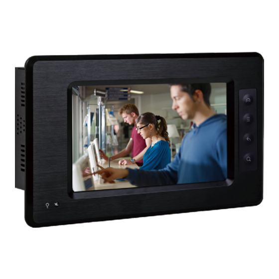
- Page 1 KS211/212 7” Touch Panel PC User’s Manual A27010427 Chapter 1 Introduction www.dfi.com...
-
Page 2: Copyright
Copyright FCC and DOC Statement on Class B This publication contains information that is protected by copyright. No part of it may be re- This equipment has been tested and found to comply with the limits for a Class B digital produced in any form or by any means or used to make any transformation/adaptation without device, pursuant to Part 15 of the FCC rules. -
Page 3: Table Of Contents
Chapter 1 - Introduction ���������������������������������������������������������������������������6 Overview �������������������������������������������������������������������������������������������������������6 Key Features ������������������������������������������������������������������������������������������������6 Specifications �����������������������������������������������������������������������������������������������7 Getting the Know the KS211/212 ���������������������������������������������������������� 9 Mechanical Dimensions ��������������������������������������������������������������������������� 10 Chapter 2 - Installation �������������������������������������������������������������� 11 Connecting Cables to Terminal Blocks ����������������������������������������������� 11 Removing the Chassis Cover ������������������������������������������������������������������12... -
Page 4: About This Manual
About this Manual Static Electricity Precautions An electronic file of this manual is included in the CD. To view the user’s manual in the CD, in- It is quite easy to inadvertently damage your PC, system board, components or devices even sert the CD into a CD-ROM drive. -
Page 5: Safety Precautions
Safety Precautions About the Package • Use the correct DC input voltage range. The package contains the following items. If any of these items are missing or damaged, please contact your dealer or sales representative for assistance. • Unplug the power cord before removing the system chassis cover for installation or servic- ing. -
Page 6: Chapter 1 - Introduction
• 7" WVGA Touch Screen Fanless Panel PC • 1GB DDR3 onboard • 4GB eMMC onboard • 4 customizable function keys (KS211) • 1 SD/MMC socket • 1 HDMI, 2 USB 2.0, 1 Mini USB, 1 LAN, 1 COM, 12-bit GPIO Chapter 1 Introduction www.dfi... -
Page 7: Specifications
Chapter 1 Specifications KS211 PROCESSOR • Freescale i.MX535 EXPANSION • 1 Mini PCIe slot (DFI Proprietary) - ARM Cortex-A8 core SLOTS - Supports half size Mini PCIe card - Processor speed: up to 1GHz - Supports USB interface for 3G module •... - Page 8 Chapter 1 Specifications KS212 PROCESSOR • Freescale i.MX535 EXPANSION • 1 Mini PCIe slot (DFI Proprietary) - ARM Cortex-A8 core SLOTS - Supports half size Mini PCIe card - Processor speed: up to 1GHz - Supports USB interface for 3G module •...
-
Page 9: Getting The Know The Ks211/212
Chapter 1 Getting to Know the KS211/212 Top View Front View SD/MMC SD/MMC Indicates to insert and SD and MMC. Power LED Function Keys Bottom View Power LED Indicates the power status of the system. Line-out USB 9-30V DC-in Function Keys (KS211) Used to navigate through the pages. -
Page 10: Mechanical Dimensions
Chapter 1 Mechanical Dimensions KS211 KS212 214.60 214.60 Top View Top View 40.80 235.00 230.40 221.00 190.00 154.40 (V,A FOR T/P) 20.20 Ø3.50 35.80 153.00 (A,A FOR T/P) Left View Front View Right View 95.00 11.20 90.00 190.00 20.20 Bottom View... -
Page 11: Chapter 2 - Installation
1. Insert the cable end of the power adaptor to the terminal block. To firmly fix the cable into the terminal block, use a screwdriver to clamp down the wires to the screw that is in the terminal block Terminal block Wire White Wire Black Wire Power adapter cable Chapter 2 Installation www.dfi.com... -
Page 12: Removing The Chassis Cover
SIM card slot chassis. Remove these screws and then put them in a safe place for later use. Mounting Screw Mounting Screw 4. After removing the mounting screws, lift the cover up. Lift the Cover Upward Chapter 2 Installation www.dfi.com... -
Page 13: Chapter 3 - Hardware Installation
RTC_Battery Panel Power Chassis Intrusion Select Power LED 3G LED (J11) JTAG Top View eMMC Touch Screen DDR3 Android Hot Key Connector Power LED Features • DDR3 onboard Bottom View • Onboard memory - 1GB: standard - 2GB: optional Chapter 3 Hardware Installation www.dfi.com... -
Page 14: Jumper Settings
1 On, 2-3 Off RS232 To load the default values stored in the ROM BIOS, please follow the steps below. 1,2 On, 3 Off RS422 1. Power-off the system and unplug the power cord. 2 On, 1,3 Off RS485 2. Set JP1 pins 2 and 3 to On. Wait for a few seconds and set JP1 back to its default setting, pins 1 and 2 On. SW4 (for COM2) is used to configure the COM port to RS232, RS422 (Full Duplex) or RS485. 3. Now plug the power cord and power-on the system. JP7 is used to configure the COM port set via the hardware mode or software mode. Note: If you use the SW4 to select RS232/ RS422/ RS485, make sure JP7 is set via the “Hardware Mode”. Chapter 3 Hardware Installation www.dfi.com... - Page 15 J11 is used to select the power that supplies with the LVDS panel. SW28 and SW29 are used to set the MMC/SD Card socket via the selections of Program Mode, eMMC Boot, or SD Boot. Important: Before powering-on the system, make sure J11’s setting matches the LVDS panel’s specification. Selecting the incorrect voltage will seriously damage the LVDS panel. Chapter 3 Hardware Installation www.dfi.com...
-
Page 16: Top Panel I/O Port
Chapter 3 Ports and Connectors Side Panel I/O Port Top Panel I/O Port 2W built-in speaker SD/MMC The front panel I/O port consist of the following: • 1 SD/MMC card socket The side panel I/O port consist of the following: •... -
Page 17: Bottom Panel I/O Ports
Chapter 3 GPIO Bottom Panel I/O Ports Line-out USB 9-30V DC-in HDMI Power Switch RS232/422/485 COM 12-bit GPIO Mini USB The bottom panel I/O ports consist of the following: • 1 12-bit GPIO (6-bit in/6-bit out) • 1 HDMI port (Type B) •... - Page 18 Chapter 3 Mini USB HDMI Mini USB HDMI The HDMI interface which carries both digital audio and video signals is used to connect a LCD monitor or digital TV that has the HDMI port. Note: The graphics features are controlled by CPU. When HDMI and LVDS displays simultaneously, the system board transmits video signals from HDMI port only.
- Page 19 Chapter 3 Line-out COM (Serial) Port Line-out COM: RS232/422/485 The pin function of COM port will vary according to JP7/SW4’s settings. Refer to “COM RS232/ RS422/RS485 Select” in this chapter for more information. The serial COM port is an asynchronous communication port with 16C550A-compatible UARTs that can be used with modems, serial printers, remote display terminals, and other serial The line-out jack is used to connect a headphone or external speakers.
-
Page 20: Lan Port
Chapter 3 USB 2.0/1.1 Ports LAN Port USB 2.0 USB 6-7 Features • SMSC 8710 10/100M Ethernet transceiver USB 2.0 The LAN port allows the system board to connect to a local area network by means of a network hub. USB allows data exchange between your computer and a wide range of simultaneously acces- sible external Plug and Play peripherals. - Page 21 Chapter 3 9~30V DC-in DC-in This DC-in terminal block provides a maximum of 60W power and is considered a low power solution. Connect a DC power cord to this jack. Use a power adapter with 9~30V DC output voltage. Using a voltage higher than the recommended one may fail to boot the system or cause damage to the system board.
-
Page 22: Chapter 4 - Mounting Options
Chapter 4 Chapter 4 - Mounting Options 3. Attach the other bracket (wall mount bracket 2) to the rear of the Panel PC. Wall Mount The wall mount kit includes the following: Mounting screw • 2 Wall mount brackets Wall mount bracket 2 •... -
Page 23: Panel Mount
Panel Mount The panel mounting kit includes the following: • 6 mounting clamps Select a place on the panel where you will mount the Panel PC. Cut out a shape on the panel that corresponds to the Panel PC’s rear dimensions (217.6mm x 128.6mm). - Page 24 Chapter 4 4. Slide the Panel PC through the hole until it is properly fi tted against the panel. 5. Position the mounting clamps along the rear edges of the Panel PC, fi tting them into the slits that are around the Panel PC. Mounting 128.60 clamp...
-
Page 25: Appendix A - Bsp User Guide
Get Android Source Code (Android/Kernel/uboot) $export CROSS_COMPILE=~/android_fs200/Android_2_3_7_sources_v115_3G/prebuilt/linux-x86/tool- Please get an Android BSP from DFI for implementing your android system, which contains chain/arm-eabi-4.3.1/bin/arm-eabi- the bootloader (uboot), kernel code, and android system, as well as tool chain, on the FS200 $make distclean board. - Page 26 UBI volumes with UBIFS format. android_recovery.img: UBI raw image is generated from "recovery/." It contains recovery UBI volumes with UBIFS format. Please use the following steps to build up the Android image: Appendix A BSP User Guide www.dfi.com...
- Page 27 (modify the init.rc, change the mmcblk0 to mmcblk1) # find . | cpio --create --format=’newc’ | gzip > ../ramdisk.img # mkimage -A arm -O linux -T ramdisk -C none -a 0x70308000 -n “Android Root Filesystem” -d ./ramdisk.img ./uramdisk.img Appendix A BSP User Guide www.dfi.com...
- Page 28 Appendix A Storage Partitions Note: /dev/sdxN, the x is the disk index from ‘a’ to ‘z’, that may be different from each The layout of the MMC/SD card or eMMC for Android system is showed below. Linux PC. • [Partition type/index] is defined in the MBR. •...
- Page 29 Appendix A MFG Tool Guide Step 3 Now you need to connect your board to one USB port on your PC. Please make sure that you The features, including windows style GUI, multiple devices support, explicit status monitoring, have set the board to the bootstrap mode before powering on the board. versatile functionalities and highly flexible architecture, make it a best choice to meet your critical timing, cost and customization requirements.
- Page 30 Appendix A Step 4 Click the “Scan” button on the main dialog to auto scan the devices connected to your PC. The other way is to click the “Options” menu at upper-right corner, and further click configura- tion item. Then, a popup window as shown below will appear. Click the “USB Ports” tab and you can view all the USB ports.
- Page 31 Appendix A You can find some information from the terminal. Step 5 Now you can find that the tool is ready to do a demo work. Click the “Start” button. If you have a terminal tool to monitor the debug serial port on your board, it is suggested to open it. You can get more information from it.
- Page 32 Appendix A How to do your own work If you are an operator in the factory, then all the knowledge you need is enough till now. But, if you are a developer, you will probably have a couple of questions such as how to burn my own image and default files, how to choose the dedicated storage device, etc.
- Page 33 Appendix A Boot from MMC/SD and eMMC Choose your own setting and click “OK” to close the window. It’s done. Then go back to the main menu after configurating and press the ‘Start’ icon to program the Before booting from the SD or eMMC device, please configure the jumper switch (SW28 and specified images.
- Page 34 Appendix A When a MMC/SD or eMMC device is ready for Android system boot, you can power on the board to setup the u-boot environment for loading the kernel/ramdisk from the device by pressing any key to enter. On the u-boot shell: U-Boot >...
-
Page 35: Appendix B - Android Bsp Known Issue
Appendix B – Android BSP Known Issue 1. The video playing cannot support the clone display with Android 2.3, provided by Freescale. The video playing is only available on the HDMI output and the KS211/212 LCD panel is blank. 2. The static IP is not supported by Android 2.3, provided by Freescale.
Need help?
Do you have a question about the KS211 and is the answer not in the manual?
Questions and answers