
Subscribe to Our Youtube Channel
Related Manuals for DFI DT122-HD


Summary of Contents for DFI DT122-HD
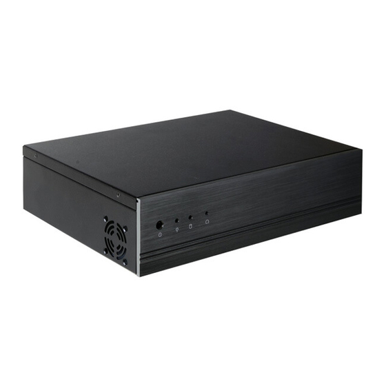
- Page 1 DT122-HD Desktop Box PC User’s Manual A36300541 Chapter 1 Introduction www.dfi .com...
-
Page 2: Copyright
Copyright FCC and DOC Statement on Class A This publication contains information that is protected by copyright. No part of it may be re- This equipment has been tested and found to comply with the limits for a Class A digital produced in any form or by any means or used to make any transformation/adaptation without device, pursuant to Part 15 of the FCC rules. -
Page 3: Table Of Contents
....................... 6 Key Features Front Panel Connector ................29 ....................6 Specifications Standby Power LED ................... 30 ....................7 Getting to Know the DT122-HD S/PDIF Connector ..................30 ............. 8 Mechanical Dimensions Expansion Slots ..................31 ................9 Motherboad Dimensions Battery ..................... 31 ................ -
Page 4: About This Manual
About this Manual Static Electricity Precautions An electronic file of this manual is included in the CD. To view the user’s manual in the CD, in- It is quite easy to inadvertently damage your PC, system board, components or devices even sert the CD into a CD-ROM drive. -
Page 5: About The Package
• Unplug the power cord before removing the system chassis cover for installation or servic- ing. After installation or servicing, cover the system chassis before plugging the power cord. • 1 DT122-HD system unit • 1 HDD drive bay kit •... -
Page 6: Chapter 1 - Introduction
Chapter 1 Chapter 1 - Introduction Key Features Overview Model Name DT122-HD ® 4th Generation Intel Core processors Processor ® Intel H81 Express chipset Chipset 2 LAN ports 2 COM ports 1 HDMI, 1 DVI-I Displays 4 USB 2.0 ports 2 USB 3.0 ports... -
Page 7: Specifications
Chapter 1 Specifications Processor System • Processors: I/O Ports • Front Panel - 4th Generation Intel ® Core processors (22nm process technology) - 1 Power button : Intel ® Core i7-4790S (8M Cache, up to 4.0 GHz); 65W - 1 Reset button ®... -
Page 8: Getting To Know The Dt122-Hd
Chapter 1 Getting to Know the DT122-HD Front View Rear View LAN 1 DVI-I Reset Button Line-in LAN 2 COM 2 Power LED PS/2 KB/MS Power Button Mic-in USB 3.0 COM 1 HDMI Line-out HDD LED USB 2.0 USB 2.0... -
Page 9: Mechanical Dimensions
Chapter 1 Mechanical Dimensions Motherboard Dimensions 10.16 Rear View 0.00 22.86 39.32 46.97 49.47 64.32 83.89 Left View Right View 300.00 107.88 124.47 140.94 Front View 153.29 154.94 154.94 159.84 Chapter 1 Introduction www.dfi .com... -
Page 10: Chapter 2 - Getting Started
Chapter 2 Chapter 2 - Getting Started Preparing the System Before you start using the system, you need the following items: • SATA hard drive • AC power adapter • PS/2 or USB keyboard • PS/2 or USB mouse • CD-ROM drive (for installing software/drivers) •... -
Page 11: Chapter 3 - Installing Devices
Chapter 3 Chapter 3 - Installing Devices 5. The DIMM sockets and SATA drive bay are readily accessible after removing the chassis cover. 1. Make sure the system and all other peripheral devices connected to it has been powered-off. 2. Disconnect all power cords and cables. 3. -
Page 12: Installing A 2.5" Or 3.5" Sata Drive
Chapter 3 Installing a 2.5" or 3.5" SATA Drive 3. Align the mounting holes of the SATA drive with the mounting holes on the HDD bracket and then use the provided mounting screws to secure the drive in place. Installing a 2.5” SATA Drive 1. - Page 13 Chapter 3 4. Turn to the other side of the drive bay. Use the provided mounting screws from step 2 to 6. Connect the SATA data cable and SATA power cable to the connectors on the SATA drive. secure the SATA drive (with HDD bracket) onto the drive bay. Drive bay Mounting screw Mounting screw...
-
Page 14: Installing A 3.5" Sata Drive
Chapter 3 lnstalling a 3.5" SATA Drive 4. Use the provided mounting screws to secure the SATA drive onto the drive bay. 1. Remove the 4 mounting screws that secure the drive bay to the system. Mounting screw Mounting screw Mounting screw Drive bay Drive bay... -
Page 15: Installing The Pci Or Pcie X16 Expansion Card
Chapter 3 Installing the PCI or PCIe x16 Expansion Card Important: When inserting the riser card, please select a card within Bracket 175mm (as shown on the next picture). Mounting bracket and mounting screw 1. The PCIe x16 on the motherboard is used to insert a TS200-1P or TS200-1E riser card. To install the expansion card, you need to remove the mounting bracket and the mounting screw that secure the bracket to the chassis and then remove the bracket. - Page 16 Chapter 3 2. Insert the Expansion card with a bracket into the PCI or PCIe x16 slot that is on the riser card. Replace the screw you removed in step 1 to secure the bracket in place. Bracket Mounting bracket and mounting screw Expansion card...
-
Page 17: Chapter 4 - Jumper Settings
Chapter 4 Chapter 4 - Jumper Settings PS/2 Keyboard/Mouse Power Select Clear CMOS Data 1-2 On: Normal (default) 1-2 On: +5V 2-3 On: (default) +5V_standby 2-3 On: Clear CMOS Data JP1 is used to select the power of the PS/2 keyboard/mouse port. Selecting +5V_standby will If you encounter the followings, allow you to use the PS/2 keyboard or PS/2 mouse to wake up the system. -
Page 18: Usb Power Select
Chapter 4 USB Power Select Power-on Select 2-3 On: 1-2 On: +5V JP10 +5V_standby (default) 1-2 On: +5V 2-3 On: (default) +5V_standby USB 0-1 (JP5) USB 2-3 (JP8) 1-2 On: USB 10-11 Power-on via power button (JP13) (default) USB 4-5 2-3 On: (JP6) Power-on via AC power... -
Page 19: Mini Pcie Signal Select
Chapter 4 Mini PCIe Signal Select LCD/Inverter Power Select JP12 1-2 On: +12V 1-4-7-10, 2-5-8-11 On: PCIe (default) 2-3 On: +5V (default) 2-5-8-11, 3-6-9-12 On: mSATA JP12 is used to select the Mini PCIe signal. JP2 is used to select the power level of LVDS LCD inverter connector. Chapter 4 Jumper Settings www.dfi... -
Page 20: Panel Power Select
Chapter 4 Panel Power Select LVDS Channel and bpp Select 1 On: Single LVDS JP11 6 4 2 1-2 On: +12V 1 Off: Dual LVDS 2 On: VESA (24bpp) 6 4 2 3-4 On:+5V 2 Off: JEIDA or VESA (18bpp) 6 4 2 5-6 On: +3.3V (default) -
Page 21: Digital I/O Power Select
Chapter 4 Digital I/O Power Select Digital I/O Output State DIO 0-3 (JP16) JP15 1-2 On: +5V or +5V_standby DIO 4-7 (default) (JP17) 1-2 On: +5V_standby (default) 2-3 On: GND 2-3 On: +5V Based on the power level of DIO (Digital I/O) selected on JP15, JP16 (DIO pin 0-3) and JP17 JP15 is used to select the power of DIO (Digital I/O) signal. -
Page 22: Chapter 5 - Ports And Connectors
Chapter 5 Chapter 5 - Ports and Connectors Rear Panel I/O Ports PS/2 Keyboard/Mouse Port PS/2 Keyboard/Mouse LAN 1 DVI-I LAN 2 Line-in COM 2 PS/2 KB/MS Mic-in COM 1 USB 3.0 HDMI Line-out USB 2.0 USB 2.0 The rear panel I/O ports consist of the following: •... -
Page 23: Rj45 Lan Ports
Chapter 5 RJ45 LAN Ports USB Ports USB 2.0 LAN 2 LAN 1 LAN 2 -Data -Data +Data +Data LAN 1 N. C. USB 2-3 USB 11 USB 10 USB 2.0 USB 1 USB 0 USB 3.0 USB 5 USB 4 Features USB 2.0 •... -
Page 24: Graphics Intefaces
Chapter 5 Graphics Interfaces Wake-On-USB Keyboard/Mouse The Wake-On-USB Keyboard/Mouse function allows you to use a USB keyboard or USB mouse The display ports consist of the following: to wake up a system from the S3 (STR - Suspend To RAM) state. To use this function: •... -
Page 25: Com (Serial) Ports
Chapter 5 COM (Serial) Ports Audio COM 2 Rear audio COM 1/COM 2: Line-in RS232 Line-out COM 1 Mic-in 1 2 3 4 5 Front audio 6 7 8 9 Line2-JD Line2-L Front_IO_Sense Mic2-JD Line2-R Presence Signal Mic2-R Mic2-L COM 1 and COM 2 are fixed at RS232. Rear Audio The serial ports are asynchronous communication ports with 16C550A-compatible UARTs that The system board is equipped with 3 audio jacks. -
Page 26: I/O Connectors
Chapter 5 I/O Connectors Digital I/O Connector Digital I/O Power Connector SATA (Serial ATA) Connectors SATA 3.0 6Gb/s Digital I/O SATA 1 SATA 0 Digital I/O power Features The 8-bit Digital I/O connector provides powering-on function to external devices that are con- •... -
Page 27: Cooling Fan Connectors
Chapter 5 Cooling Fan Connectors Power Connectors 12 24 +3.3V +12V ATX power Ground +12V System Fan Power +5VSB Sense PWR_OK Ground PS_ON# Power Sense CPU Fan +3.3V -12V Speed Control +3.3V +3.3V +12V Power +12V Ground The fan connectors are used to connect cooling fans. The cooling fans will provide adequate Ground airflow throughout the chassis to prevent overheating the CPU and system board components. -
Page 28: Lvds Lcd Panel Connector
Chapter 5 LVDS LCD Panel Connector LVDS LCD Panel Connector LCD/Inverter Power Connector LCD/Inverter Power Connector Pins Function Pins Function Pins Function LCD/Inverter LVDS_Out3+ LVDS_Out7+ power Panel Inverter Brightness Voltage Control LVDS_Out3- LVDS_Out7- Panel Power +3.3V LVDS_Out2+ LVDS_Out6+ Panel Backlight On/Off Control LVDS_Out2- LVDS_Out6- LCD/Inverter Power... -
Page 29: Chassis Intrusion Connector
Chapter 5 Chassis Intrusion Connector Front Panel Connector 12 11 Chassis Front Intrusion Panel ATX-SW RESET-SW HDD-LED PWR-LED Signal Ground HDD-LED - HDD LED This LED will light when the hard drive is being accessed. The board supports the chassis intrusion detection function. Connect the chassis intrusion sensor cable from the chassis to this connector. -
Page 30: Standby Power Led
Chapter 5 Standby Power LED S/PDIF Connector Standby Power LED SPDIF in Ground SPDIF out S/PDIF This LED will lit red when the system is in the standby mode. It indicates that there is power The S/PDIF connector is used to connect an external S/PDIF port. Your S/PDIF port may be on the system board. -
Page 31: Expansion Slots
Chapter 5 Expansion Slots Battery Battery Mini PCI Express PCI Express x16 PCI Express x16 Slot The lithium ion battery powers the real-time clock and CMOS memory. It is an auxiliary source Install PCI Express x16 graphics card, that comply to the PCI Express specifications, into the of power when the main power is shut off. -
Page 32: Chapter 6 - Mounting Options
Chapter 6 Chapter 6 - Mounting Options 2. At the sides of the system, use the mounting screws removed in step 1 to secure the wall mount brackets on each side of the system. Wall Mount Note: The system unit used in the following illustrations may not resemble the actual one. Wall mount bracket These illustrations are for reference only. - Page 33 Chapter 6 Type B wall mount kit include: • 2 type B wall mount brackets • Bracket screws 1. The 4 mounting holes on the sides of the system are used to mount the type B wall mount bracket. Ø8.50 R2.50 5.00 5.00...
-
Page 34: Chapter 7 - Bios Setup
Chapter 7 Chapter 7 - BIOS Setup Legends Overview Keys Function The BIOS is a program that takes care of the basic level of communication between the CPU and peripherals. It contains codes for various advanced features found in this system board. Moves the highlight left or right to select a menu. -
Page 35: Ami Bios Setup Utility
Chapter 7 AMI BIOS Setup Utility Advanced The Advanced menu allows you to configure your system for basic operation. Some entries are Main defaults required by the system board, while others, if enabled, will improve the performance of your system or let you set some features according to your preference. The Main menu is the first screen that you will see when you enter the BIOS Setup Utility. - Page 36 Chapter 7 ACPI Power Management Configuration Trusted Computing This section is used to configure the ACPI Power Management. This section configures settings relevant to Trusted Computing innovations. Aptio Setup Utility - Copyright (C) 2012 American Megatrends, Inc. Aptio Setup Utility - Copyright (C) 2012 American Megatrends, Inc. Advanced Advanced Confi...
- Page 37 Chapter 7 CPU Configuration SATA Configuration This section is used to configure the CPU. It will also display the detected CPU information. This section is used to configure the settings of SATA device. Aptio Setup Utility - Copyright (C) 2012 American Megatrends, Inc. Aptio Setup Utility - Copyright (C) 2012 American Megatrends, Inc.
- Page 38 Chapter 7 When IDE mode is selected in the SATA Mode Selection, it will display the following SATA Controller Speed information: Indicates the maximum speed that the SATA controller can support. Aptio Setup Utility - Copyright (C) 2012 American Megatrends, Inc. Port 0, Port 1 and Port 4 Advanced SATA Controller(s)
- Page 39 Chapter 7 PCH-FW Configuration USB Configuration This section is used to configure the parameters of Management Engine Technology. This section is used to configure the parameters of the USB device. Aptio Setup Utility - Copyright (C) 2012 American Megatrends, Inc. Aptio Setup Utility - Copyright (C) 2012 American Megatrends, Inc.
- Page 40 Chapter 7 Super IO Configuration Serial Port 0 Configuration to Serial Port 1 Configuration This section is used to configure the I/O functions supported by the onboard Super I/O chip. Sets the parameters of serial port 0 (COM A) and serial port 1 (COM B). Aptio Setup Utility - Copyright (C) 2012 American Megatrends, Inc.
- Page 41 Chapter 7 System Smart Fan Control PC Health Status When this feature is set to Automatic, the System’s fan speed will rotate according to This section displays the hardware health monitor. the System’s temperature. The higher the temperature, the faster the speed of rotation. Aptio Setup Utility - Copyright (C) 2012 American Megatrends, Inc.
- Page 42 Chapter 7 Network Stack Ipv4 PXE Support When enabled, Ipv4 PXE boot supports. When disabled, Ipv4 PXE boot option will not Aptio Setup Utility - Copyright (C) 2012 American Megatrends, Inc. be created. Advanced Network Stack [Enabled] Enable or disable UEFI Ipv6 PXE Support network stack.
- Page 43 Chapter 7 Intel(R) Ethernet Network Connection i217-LM - 88:88:88:... Intel(R) I210 Gigabit Network Connection - 00:01:29:26... (Only for reference) (Only for reference) This section is used to configure the parameters of Gigabit Ethernet device. This section is used to configure the parameters of Gigabit Ethernet device. Aptio Setup Utility - Copyright (C) 2012 American Megatrends, Inc.
-
Page 44: Chipset
Chapter 7 Chipset Graphics Configuration This field configures the graphics settings. This section configures relevant chipset functions. Aptio Setup Utility - Copyright (C) 2012 American Megatrends, Inc. Aptio Setup Utility - Copyright (C) 2012 American Megatrends, Inc. Main Advanced Chipset Boot Security Save &... - Page 45 Chapter 7 LCD Control LCD Panel Type This field configures the LCD control. Selects LCD panel used by Internal Graphics Device via selecting the appropriate setup item. Aptio Setup Utility - Copyright (C) 2012 American Megatrends, Inc. Chipset Aptio Setup Utility - Copyright (C) 2012 American Megatrends, Inc. Chipset LCD Control Select the Video Device...
- Page 46 Chapter 7 NB PCIe Configuration Memory Configuration This field is used to configure the settings of NB PCI Express. This field only displays the memory configuration. Aptio Setup Utility - Copyright (C) 2012 American Megatrends, Inc. Aptio Setup Utility - Copyright (C) 2012 American Megatrends, Inc. Chipset Chipset NB PCIe Confi...
- Page 47 Chapter 7 PCH-IO Configuration PCI Express Configuration This section illustrates the PCH parameters. This field is used to configure the PCI Express settings. Aptio Setup Utility - Copyright (C) 2012 American Megatrends, Inc. Aptio Setup Utility - Copyright (C) 2012 American Megatrends, Inc. Chipset Chipset PCI Express Confi...
- Page 48 Chapter 7 XHCI Mode USB Configuration Selects the operation mode of XHCI controller. These options are Auto, Enabled, This field is used to configure the USB settings. and Disabled. When Disabled is selected in the XHCI Mode, it will display the following information: Aptio Setup Utility - Copyright (C) 2012 American Megatrends, Inc.
- Page 49 Chapter 7 USB Ports Per-Port Disable Control PCH Azalia Configuration This field is used to control each of the USB ports(0~13) disabling. When enabled, This field is used to configure the PCH Azalia settings. it will display the following information: Aptio Setup Utility - Copyright (C) 2012 American Megatrends, Inc.
-
Page 50: Boot
Chapter 7 Boot CSM Parameters Aptio Setup Utility - Copyright (C) 2012 American Megatrends, Inc. Aptio Setup Utility - Copyright (C) 2012 American Megatrends, Inc. Main Advanced Chipset Boot Security Save & Exit Main Advanced Chipset Boot Security Save & Exit Boot Confi... -
Page 51: Security
Chapter 7 Security Save & Exit Aptio Setup Utility - Copyright (C) 2012 American Megatrends, Inc. Aptio Setup Utility - Copyright (C) 2012 American Megatrends, Inc. Main Advanced Chipset Boot Security Save & Exit Main Advanced Chipset Boot Security Save & Exit Password Description Set Administrator Save Changes and Reset... -
Page 52: Updating The Bios
Chapter 7 Updating the BIOS Notice: BIOS SPI ROM To update the BIOS, you will need the new BIOS file and a flash utility, AFUDOS. 1. The Intel Management Engine has already been integrated into this system board. Due to ®... -
Page 53: Chapter 8 - Supported Software
Chapter 8 Chapter 8 - Supported Software For Windows 7 The CD that came with the system board contains drivers, utilities and software applications required to enhance the performance of the system board. Insert the CD into a CD-ROM drive. The autorun screen (Mainboard Utility CD) will appear. If after inserting the CD, “Autorun”... -
Page 54: Intel Chipset Software Installation Utility
Chapter 8 Intel Chipset Software Installation Utility 3. Go through the readme document for more installa- tion tips then click Next. The Intel Chipset Software Installation Utility is used for updating Windows INF files so that ® the Intel chipset can be recognized and configured properly in the system. To install the utility, click “Intel Chipset Software Installation Utility”... - Page 55 Chapter 8 Intel HD Graphics Drivers 3. Go through the readme document for system re- quirements and installation To install the driver, click “Intel HD Graphics Drivers” on the main menu. tips then click Next. 1. Setup is now ready to install the graphics driver.
- Page 56 Chapter 8 Intel Management Engine Drivers 3. Setup is currently installing the driver. After installation has completed, click Next. To install the driver, click “Intel Management Engine Drivers” on the main menu. 1. Setup is ready to install the driver. Click Next. 4.
- Page 57 Chapter 8 Audio Drivers Intel LAN Drivers To install the driver, click “Audio Drivers” on the main menu. To install the driver, click “Intel LAN Drivers” on the main menu. 1. Setup is ready to install the 1. Setup is ready to install the driver.
- Page 58 Chapter 8 NuvSerial 4. Click Install to begin the installation. To install the driver, click “NuvSerial” on the main menu. 1. The setup program is preparing to install the driver. 5. After completing installa- tion, click Finish. 2. The setup program is now ready to install the utility.
- Page 59 Chapter 8 Intel USB 3.0 Drivers (For Windows 7) 4. Installing status. To install the driver, click “Intel USB 3.0 Driver” on the main menu. 1. Setup is ready to install the driver. Click Next. 5. Click “Finish“ to exit the wizard after the installation is completed.
-
Page 60: Intel Rapid Storage Technology
Chapter 8 Intel Rapid Storage Technology 3. Go through the readme docu- ment for more installation tips then click Next. The Intel Rapid Storage Technology is a utility that allows you to monitor the current status of the SATA drives. It enables enhanced performance and power management for the storage subsystem. - Page 61 Chapter 8 3. Read the license agreement then 6. Click “Yes, I want to restart my click Yes. computer now” then click Finish. Restarting the system will allow the new software installation to take effect. 4. Go through the readme document for system requirements and instal- lation tips then click Next.
- Page 62 Chapter 8 Adobe Acrobat Reader 9.3 To install the reader, click “Adobe Acrobat Reader 9.3” on the main menu. 1. Click Next to install or click Change Destination Folder to select another folder. 2. Click Install to begin installa- tion. 3.
-
Page 63: Chapter 9 - Digital I/O Programming Guide
Chapter 9 Chapter 9 - Digital I/O Programming Guide The Configuration Register (register 3) configures the direction of the I/O pins. If a bit in this register is set to 1, the corresponding port pin is enabled as an input with a high-impedence Register Description output driver. -
Page 64: Function Description
Chapter 9 Function Description GPIO Output Process I2CWriteByte(SlaveAddr, SubAddr, Data): #defi ne SLAVE_ADDR 0x42 Write a Byte data to a specified I2C Device. #defi ne INPUT_PORT 0x00 #defi ne OUTPUT_PORT 0x01 I2CReadByte(SlaveAddr, SubAddr, *Data): 0x02 #defi ne INVERSION_PORT Read a Byte data from a specified I2C Device. 0x03 #defi... -
Page 65: Appendix A - Watchdog Sample Code
Appendix A Appendix A - Watchdog Sample Code ;Software programming example: ;--------------------------------------------- ;(1) Enter Super IO Confi guration mode ;--------------------------------------------- DX,4EH AL,87H DX,AL DX,AL ;------------------------------------------------------------------------------------------- ;(2) Confi guration Logical Device 8, register CRF0/CRF1 (WDT Control/WDT timer) ;------------------------------------------------------------------------------------------- DX,4EH AL,07H ;Ready to Program Logical Device DX,AL DX,4FH AL,08H... -
Page 66: Appendix B - System Error Message
Appendix B Appendix B - System Error Message Hard Disk(s) fail (20) When the BIOS encounters an error that requires the user to correct something, either a beep HDD initialization error. code will sound or a message will be displayed in a box in the middle of the screen and the message, PRESS F1 TO CONTINUE, CTRL-ALT-ESC or DEL TO ENTER SETUP, will be shown in Hard Disk(s) fail (10) the information box at the bottom. -
Page 67: Appendix C - Troubleshooting Checklist
Appendix C Appendix C - Troubleshooting Checklist The picture seems to be constantly moving. Troubleshooting Checklist 1. The monitor has lost its vertical sync. Adjust the monitor’s vertical sync. 2. Move away any objects, such as another monitor or fan, that may be creating a magnetic This chapter of the manual is designed to help you with problems that you may encounter field around the display. -
Page 68: Hard Drive
Appendix C Hard Drive System Board 1. Make sure the add-in card is seated securely in the expansion slot. If the add-in card is Hard disk failure. loose, power off the system, re-install the card and power up the system. 1.
Need help?
Do you have a question about the DT122-HD and is the answer not in the manual?
Questions and answers