
Related Manuals for DFI RM641


Summary of Contents for DFI RM641
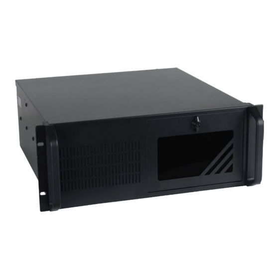
- Page 1 RM641-SD Desktop Box IPC User’s Manual A44010952 Chapter 1 Introduction www.dfi.com...
-
Page 2: Copyright
Product names or trademarks appearing in this manual are for identification purpose only and Shielded interface cables must be used in order to comply with the emission limits. are the properties of the respective owners. Chapter 1 Introduction www.dfi.com... -
Page 3: Table Of Contents
Chapter 7 - Supported Software....44 Overview .................6 Chapter 8 - RAID .........62 Specifications ................7 Getting to Know the RM641-SD ..........8 Chapter 9 - Intel AMT Settings ....66 Chapter 2 - Getting Started......10 Appendix A - System Error Message..79 Preparing the System ............. 10 Installing Devices .............. -
Page 4: About This Manual
About this Manual Static Electricity Precautions An electronic file of this manual can be obtained from the DFI website at www.dfi.com. It is quite easy to inadvertently damage your PC, system board, components or devices even To download the user’s manual from our website, please go to “Support” > “Download Center.”... -
Page 5: Safety Precautions
• Unplug the power cord before removing the system chassis cover for installation or servic- ing. After installation or servicing, cover the system chassis before plugging the power cord. • 1 RM641 system unit • 1 SATA Cable • Danger of explosion if battery incorrectly replaced. -
Page 6: Chapter 1 - Introduction
Chapter 1 Chapter 1 - Introduction Key Features Overview Model Name RM641-SD Processor 6th generation Intel ® Core processors Chipset Intel® Q170 Chipset 2 LAN ports 1 COM port Display 1 HDMI, 1 VGA, DVI-I (DVI-D signal) 2 USB 2.0 ports at the rear panel I/O ports;... -
Page 7: Specifications
ISTA Project 1A Package Drop 1 x HDD LED Certification Front I/O 2 x USB 2.0 (available upon request) Front 1 x Drive Panel Door With Keylock Door Buttons 1 x Power Switch 1 x Reset Switch Chapter 1 Introduction www.dfi.com... -
Page 8: Getting To Know The Rm641-Sd
Chapter 1 Getting to Know the RM641-SD Front View Rear View Reset Power LED HDD LED Power USB 2.0 DC-in Jack LAN 1-2 USB 3.0 Line-out DVI-I Mic-in keyboard/mouse HDMI USB 2.0 Power Button DC-in jack Press to power on or power off the system. - Page 9 Chassis Dimensions Motherboard Dimensions Rear View 429.80 10.16 0.00 22.86 46.94 75.29 93.99 144.25 150.29 154.94 154.94 167.08 2 10 174.85 185.28 187.28 2 10 482.60 194.68 464.60 227.33 227.33 233.68 RESET POWER H.D.D. POWER Front View Chapter 1 Introduction www.dfi.com...
-
Page 10: Chapter 2 - Getting Started
Please refer to your operating system manual for instructions on installing an operating system. Installing the Drivers The system requires you to install drivers for some devices to operate properly. Refer to the Supported Software chapter for instructions on installing the drivers. Chapter 2 Getting Started www.dfi.com... -
Page 11: Chapter 3 - Installing The Device
2. Align the mounting holes of the SATA drive with the mounting holes on the HDD brackets and 4. The DIMM sockets are readily accessible after removing the chassis cover. then use the mounting screws to secure the drive in place. Mounting screw SATA drive DIMM socket HDD bracket Chapter 3 Installing the Device www.dfi.com... - Page 12 The system can accommodate 4 disks (3.5” or 2.5”). However, 3.5” to 5.25” or 2.5” to 5.25” drive mounting bracket adapters will be required to install HDDs in the optical bays. SATA power and data connector Chapter 3 Installing the Device www.dfi.com...
-
Page 13: Installing The Dimm Module
2. Make sure to keep the protective cap. RMA requests will be accepted and pro- cessed only if the LGA 1151 socket comes with the protective cap. CPU socket DIMM socket Protective Cap Chapter 3 Installing the Device www.dfi.com... - Page 14 5. Lift the load lever to lift the load plate. Lift the load lever up to the angle shown on the photo. Gold triangular mark Important: The CPU will fit in only one orientation and can easily be inserted without exerting any force. Chapter 3 Installing the Device www.dfi.com...
-
Page 15: Installing The Fan And Heat Sink
4 mounting holes “Unlocked” position around the socket. “Locked” position of of push-pin push-pin 5. Connect the CPU fan’s cable to the CPU fan connector on the system board. CPU Fan connector Chapter 3 Installing the Device www.dfi.com... -
Page 16: Installing The Pci/Pcie Expansion Card
Secure the PCIe expansion card to the system with the screws. Make sure the PC and all other peripheral devices connected to it has been powered down. Disconnect all power cords and cables. Take off the card bracket secured on the system’s chassis. Chapter 3 Installing the Device www.dfi.com... -
Page 17: Chapter 4 - Jumper Settings
2. Set JP9 pins 2 and 3 to On. Wait for a few seconds and set JP9 back to its default setting, pins 1 and 2 On. 3. Now plug the power cord and power-on the system. Chapter 4 Jumper Settings www.dfi.com... -
Page 18: Com1/Com2 Rs232/422/485 Select
1. When COM 1 RS232/422/485 is selected, JP6 and JP7 must be set in accordance to JP5. 2. When COM 2 RS232/422/485 is selected, JP2 and JP3 3-4 On: RS422 5-6 On: RS485 1-2 On: RS232 must be set in accordance to JP1. Full Duplex (default) Chapter 4 Jumper Settings www.dfi.com... -
Page 19: Com1/Com2 Rs232/Power Select
JP8 (for COM 1) and JP4 (for COM 2) are used to configure Serial COM ports to pure RS232 or RS232 with power. The pin functions of COM 1 and COM 2 will vary according to JP8’s and JP4’s setting respectively. Chapter 4 Jumper Settings www.dfi.com... -
Page 20: Chapter 5 - Ports And Connectors
If you are using the Wake-On-USB Keyboard/Mouse function for 2 USB ports, the +5V_standby power source of your power supply must support ≥1.5A. For 3 or more USB ports, the +5V_standby power source of your power supply must support ≥2A. Chapter 5 Ports and Connectors www.dfi.com... -
Page 21: Rear Panel I/O Ports
Configure the wake-up function of PS/2 keyboard/mouse in the Advanced menu (“ACPI Con- figuration” submenu) of the BIOS. Refer to the chapter 3 for more information. Important: The +5V_standby power source of your power supply must support ≥720mA. Chapter 5 Ports and Connectors www.dfi.com... - Page 22 Configure the serial COM ports in the Advanced menu (“SIO NUVOTON6106D” submenu) of Configure the display devices in the Advanced menu (“Video Configuration” submenu) of the the BIOS. Refer to the chapter 3 for more information. BIOS. Refer to the chapter 3 for more information. Chapter 5 Ports and Connectors www.dfi.com...
- Page 23 BIOS. Refer to the chapter 3 for more information. Driver Installation You may need to install the proper drivers in your system operation to use the USB device. Refer to your operating system’s manual or documentation for more information. Chapter 5 Ports and Connectors www.dfi.com...
- Page 24 This jack is used to connect a headphone or external speakers. • Mic-in Jack (Pink) This jack is used to connect an external microphone. Driver Installation Install the audio driver. Refer to the chapter 4 for more information. Chapter 5 Ports and Connectors www.dfi.com...
-
Page 25: I/O Connectors
8 series chipset are intermittently detected. Before using SSD devices ® DIO0 or mSATA SSD devices, please check whether the device and the cable which are used on the system board conform to Intel’s official regulations. Chapter 5 Ports and Connectors www.dfi.com... - Page 26 Insufficient power supplied to the system may result in instability or the add-in boards and peripherals not functioning properly. Calculating the system’s approximate power usage is important to ensure that the power supply meets the system’s consumption requirements. Chapter 5 Ports and Connectors www.dfi.com...
- Page 27 On Suspend) state, it will blink every second. When the system is in the S3 (STR - Suspend To RAM) state, it will blink every 4 seconds. Pin Pin Assignment Pin Pin Assignment HDD Power LED Power HDD-LED Signal PWR-LED LED Power Ground Signal RST Signal Ground RESET SW ATX-SW N.C. Signal Chapter 5 Ports and Connectors www.dfi.com...
- Page 28 PCI card only) into the PCI slot. PCI Express x4 Slot Install PCI Express cards such as network cards or other cards that comply to the PCI Express specifications into the PCI Express x4 slot. Chapter 5 Ports and Connectors www.dfi.com...
- Page 29 1 of the S/PDIF connector. Safety Measures • Danger of explosion if battery incorrectly replaced. • Replace only with the same or equivalent type recommend by the manufacturer. • Dispose of used batteries according to local ordinance Chapter 5 Ports and Connectors www.dfi.com...
-
Page 30: Chapter 6 - Bios Setup
When ““ appears on the left of a particular field, it indicates that a submenu which contains additional options are available for that field. To display the submenu, move the highlight to that field and press <Enter>. Chapter 6 BIOS Setup www.dfi.com... -
Page 31: Insyde Bios Setup Utility
The time format is <hour>, <minute>, <second>. The time is based on the 24-hour military-time clock. For example, 1 p.m. is 13:00:00. Hour displays hours from 00 to 23. Minute displays minutes from 00 to 59. Second displays seconds from 00 to 59. Chapter 6 BIOS Setup www.dfi.com... - Page 32 This field is to specify what state to go when power is re-applied after a power failure (G3 state). S0 State The system working state. S5 State Off, except for trickle current to devices such as the power button. Chapter 6 BIOS Setup www.dfi.com...
- Page 33 Video Configuration on the setup options. Internal Graphics <Auto> Always Enabled PEG <Disabled> Boot display <VGA+DVI> Help ↑/↓ Select Item F5/F6 Change Values Setup Defaults Exit ←/→ Select Item Enter Select SubMenu Save and Exit Chapter 6 BIOS Setup www.dfi.com...
- Page 34 This option allows you to create RAID or Intel Matrix Storage configuration on Serial ATA devices. Serial ATA Port 0, 1, 2, 3, 4, and 5 This field is used to enable or disable the serial ATA port. Chapter 6 BIOS Setup www.dfi.com...
- Page 35 Save and Exit PCI Express Root Port This field is used to enable or disable the PCI Express Root Port. PCIe Speed Select the speed of the PCI Express Root Port: Auto, Gen1, Gen2 or Gen3. Chapter 6 BIOS Setup www.dfi.com...
- Page 36 This field is used to enable or disable the flash ME region. This field is used to enable or disable Intel(R)Active Management Technology BIOS Extension. Un-Configure ME This field is used to enable or disable un-figuring ME without password. Chapter 6 BIOS Setup www.dfi.com...
- Page 37 Configure the settings to use the serial port. Fan Speed Count 1 to Fan Speed Count 4 Disable No configuration Set the fan speed. The range is from 1-100%. Enable User configuration RS485 Auto Flow Enable or disable RS485 auto flow. Chapter 6 BIOS Setup www.dfi.com...
- Page 38 Base I/O Address <2E8> Interrupt <IRQ3> COM Port 5 <Enable> Base I/O Address <2F0> Interrupt <IRQ4> Help ↑/↓ Select Item F5/F6 Change Values Setup Defaults Exit ←/→ Select Item Enter Select SubMenu Save and Exit Chapter 6 BIOS Setup www.dfi.com...
-
Page 39: Security
This option allowes you to go to Storage Password List Help. Set all master HDD password and suggest the length of password greater than one character. This item can be displayed when any security mode of HDD is not Lock. Chapter 6 BIOS Setup www.dfi.com... -
Page 40: Boot
Only pressing “Enter” would clear HDD password and make HDD secutiry disable PXE Boot Capability when set new master HDD password. Disabled : Suppoort Network Stack UEFI PXE : IPv4/IPv6 Legacy : Legacy PXE OPROM only Chapter 6 BIOS Setup www.dfi.com... - Page 41 Select Normal Boot Option Boot Device Priority Priority or Advance Boot Option Priority Normal Boot Menu <Normal> Help ↑/↓ Select Item F5/F6 Change Values Setup Defaults Exit ←/→ Select Item Enter Select SubMenu Save and Exit Chapter 6 BIOS Setup www.dfi.com...
-
Page 42: Exit
Select this field and then press <Enter> to exit the system setup and save your changes. Load Optimal Defaults Select this field and then press <Enter> to load optimal defaults. Discard Changes Select this field and then press <Enter>to exit the system setup without saving your changes. Chapter 6 BIOS Setup www.dfi.com... -
Page 43: Updating The Bios
Copyright(c) 2012 - 2016, Insyde Software Corp. All Rights Reserved. Initializing Current BIOS Model name: SD631-Q170/C236 New BIOS Model name: SD631-Q170/C236 Current BIOS version: 65.05A New BIOS version: 65.05A Updating Block at FFFFF000h 100% 100% C:\SD631-Q170/C236>_ Chapter 6 BIOS Setup www.dfi.com... -
Page 44: Chapter 7 - Supported Software
“Setup”. If your product package does not include a CD/DVD, you can download the latest drivers from the DFI Download Center: http://www.dfi.com/DownloadCenter Once you are in the Download Center page, select your product or type the model name and click "Search"... - Page 45 Intel chipset can be recognized and configured properly in the system. To install the utility, click “Intel Chipset Software Installation Utility” on the main menu. 1. Setup is ready to install the utility. Click Next. 2. Read the license agreement then click Yes. Chapter 7 Supported Software www.dfi.com...
- Page 46 1 to 2 minutes (while WinSAT is running) before the Windows 7/Windows 8.1/Windows 10 desktop appears. The “blank screen” period is the time Windows is testing the graphics performance. 2. Read the license agreement then click Yes. Chapter 7 Supported Software www.dfi.com...
- Page 47 Restarting the system will allow the new software installation to take effect. 5. Click “Yes, I want to restart this computer now” then click Finish. Restarting the system will allow the new software installation to take effect. Chapter 7 Supported Software www.dfi.com...
- Page 48 1. Setup is ready to install the driver. Click Next. 5. After completing installa- tion, click Finish. 2. Click “I accept the terms in the license agreement” then click “Next”. 3. Select the program features you want installed then click Next. Chapter 7 Supported Software www.dfi.com...
- Page 49 3. Click “Restart Now“ to restart your computer when the installation is complete. To install the driver, click “Kernel Mode Driver Framework” on the main menu. 1. Click “Yes“ to install the update. 2. The update is installed now. Chapter 7 Supported Software www.dfi.com...
- Page 50 1. Setup is ready to install the driver. Click Next. 4. Please wait while the prod- uct is being installed. 2. Read the license agreement then click Next. 5. After completing installa- tion, click Finish. Chapter 7 Supported Software www.dfi.com...
- Page 51 1. Setup is ready to install the driver. 4. The wizard is ready to begin installation. Click “Install”. 2. Click “Next” to continue. 5. Please wait while the program features are being installed. Chapter 7 Supported Software www.dfi.com...
- Page 52 Note: The screenshot displayed above is for illustrative purpose only, and may not resemble the actual screen. The SD631-C236/Q170 HW Utility features the following tabs: Information, HW Health, HW Healthset, Watchdog, and DIO. Click on the tabs to access information about the board. Chapter 7 Supported Software www.dfi.com...
- Page 53 1. Setup is ready to install the driver. Click Next. 4. Setup is currently installing the driver. After installation has com- pleted, click Next. 2. Read the license agreement then click Yes. 5. After completing installation, click Finish. Chapter 7 Supported Software www.dfi.com...
- Page 54 1. Setup is ready to install the driver. Click Next. 4. Setup is ready to install the driver. Click Next. 2. Read the license agreement then Click “I accept the terms click Yes. in the License Agreement” then click Next. Chapter 7 Supported Software www.dfi.com...
- Page 55 To install the driver, click “Microsoft Framework 4.5.2” on the main menu. 1. Setup is now extracting files. 6. Click Finish. 2. Read the license agreement care- fully. Click “I have read and accept the terms of the License Agree ment” then click Install. Chapter 7 Supported Software www.dfi.com...
- Page 56 SATA drives. It enables enhanced performance and power management for the storage subsystem. To install the driver, click “Intel Rapid Storage Technology” on the main menu. Please refer to next chapter for more information. 4. Click Finish. Chapter 7 Supported Software www.dfi.com...
- Page 57 5. Select a setup type and then click Next. 2. The setup program is now ready to install the utility. Click Next. 6. Click Install. 3. Click “I accept the terms in the license agreement” and then click “Next”. Chapter 7 Supported Software www.dfi.com...
- Page 58 7. TPM requires installing the Micro- 10. Click “Yes“ to restart your system. soft Visual C++ package prior to installing the utility. Click Install. 8. The setup program is currently installing the Microsoft Visual C++ package. 9. Click Finish. Chapter 7 Supported Software www.dfi.com...
- Page 59 Select a setup type and then click Next. The setup program is now ready to install the utility. Click Next. Click Install. Click “I accept the terms in the license agreement” and then click “Next”. Chapter 7 Supported Software www.dfi.com...
- Page 60 TPM requires installing the Microsoft 10. Click “Yes“ to restart your system. Visual C++ package prior to install- ing the utility. Click Install. The setup program is currently installing the Microsoft Visual C++ package. Click Finish. Chapter 7 Supported Software www.dfi.com...
- Page 61 To install the reader, click “Adobe Acrobat Reader 9.3” on the main menu. 1. Click Next to install or click Change Destination Folder to select another folder. 2. Click Install to begin installa- tion. 3. Click Finish to exit installation. Chapter 7 Supported Software www.dfi.com...
-
Page 62: Chapter 8 - Raid
Single Drive Failure Disk mirroring Block-level data striping with RAID 5 Single Drive Failure distributed parity 1 Disk Per Mirrored Combination of RAID 0 (data striping) RAID 10 Stripe (not same mirror) and RAID 1 (mirroring) Chapter 8 RAID www.dfi.com... - Page 63 6. Press <Enter>. 7. Use the up or down arrow keys to select the strip size and press <Enter>. 8. Enter the volume size and press <Enter>. 9. At the prompt, press <Y> to confirm volume creation. Chapter 8 RAID www.dfi.com...
- Page 64 4. Read the license agree- ment and click “I accept the terms in the License Agreement.“ Then, click Next. Chapter 5 RAID 7. Confirm the installation and click Next. Chapter 8 RAID www.dfi.com...
- Page 65 Chapter 8 Chapter 5 8. Click “Yes, I want to restart this computer now” to complete the installation and then click Finish. Chapter 5 RAID Chapter 8 RAID www.dfi.com...
-
Page 66: Chapter 9 - Intel Amt Settings
Help ↑/↓ Select Item F5/F6 Change Values Setup Defaults Exit ←/→ Select Item Enter Select SubMenu Save and Exit Un-Configure ME Un-configure ME without password. You can select enabled or disabled. Chapter 9 Intel AMT Settings www.dfi.com... - Page 67 MEBx Exit Help ↑/↓ Select Item F5/F6 Change Values Setup Defaults Exit ←/→ Select Item Enter Select SubMenu Save and Exit Intel(R) ME Password [↑↓] = Move Highlight [Enter] = Select Entry [Esc]= Exit Chapter 9 Intel AMT Settings www.dfi.com...
- Page 68 Intel(R) Management Engine BIOS Extension v11.0.0.0005/Intel(R) ME v11.0.0.1205 Copyright(C) 2003-15 Intel Corporation. All Rights Reserved. MAIN MENU > Intel (R) ME General Settings > Intel (R) AMT Configuration MEBx Exit [↑↓] = Move Highlight [Enter] = Select Entry [Esc]= Exit Chapter 9 Intel AMT Settings www.dfi.com...
- Page 69 > User Consent Password Policy <Anytime> > Network Setup Activate Network Access Unconfigure Network Access <Full Unprovision> > Remote Setup And Configuration > Power Control [↑↓] = Move Highlight [Enter] = Select Entry [Esc]= Exit Chapter 9 Intel AMT Settings www.dfi.com...
- Page 70 <Full Unprovi- Disabled sion> Enabled > Remote Setup And Configuration > Power Control [↑↓] = Move Highlight [Enter] = Select Entry [Esc]= Exit [↑↓] = Move Highlight [Enter] = Complete Entry [Esc]= Discard Changes Chapter 9 Intel AMT Settings www.dfi.com...
- Page 71 < Enabled> Storage Redirection <Enabled> KVM Feature Selection <Enabled> NONE Disabled Enabled [↑↓] = Move Highlight [Enter] = Complete Entry [Esc]= Discard Changes [↑↓] = Move Highlight [Enter] = Complete Entry [Esc]= Discard Changes Chapter 9 Intel AMT Settings www.dfi.com...
- Page 72 > Remote Setup And Configuration > Power Control Default Password Only During Stepup And Configuration Anytime [↑↓] = Move Highlight [Enter] = Select Entry [Esc]= Exit [↑↓] = Move Highlight [Enter] = Complete Entry [Esc]= Discard Changes Chapter 9 Intel AMT Settings www.dfi.com...
- Page 73 Shared/ Dedicated FQDN <Shared> Dynamic DNS Update <Disabled> Dynamic DNS Update <Disabled> Computer Domain Name Disabled Enabled [Enter] = Complete Entry [Esc]= Discard Changes [↑↓] = Move Highlight [Enter] = Complete Entry [Esc]= Discard Changes Chapter 9 Intel AMT Settings www.dfi.com...
- Page 74 Unconfigure Network Access > Remote Setup And Configuration Full Unprovision > Power Control [↑↓] = Move Highlight [Enter] = Complete Entry [Esc]= Discard Changes [↑↓] = Move Highlight [Enter] = Complete Entry [Esc]= Discard Changes Chapter 9 Intel AMT Settings www.dfi.com...
- Page 75 > TLS PKI > TLS PKI Provisioning Mode:PKI Provisioning server address [ESC] = Exit [↑↓] = Move Highlight [Enter] = Select Entry [Esc]= Exit [↑↓] = Move Highlight [Enter] = Select Entry [Esc]= Exit Chapter 9 Intel AMT Settings www.dfi.com...
- Page 76 This will activate Remote Condigura- tion. Continue: (Y/N) Disabled Enabled [ESC] = Exit [ESC] = Exit [↑↓] = Move Highlight [Enter] = Select Entry [Esc]= Exit [↑↓] = Move Highlight [Enter] = Select Entry [Esc]= Exit Chapter 9 Intel AMT Settings www.dfi.com...
- Page 77 Activate Network Access Unconfigure Network Access <Full Unprovision> > Remote Setup And Configuration > Power Control [↑↓] = Move Highlight [Enter] = Select Entry [Esc]= Exit [↑↓] = Move Highlight [Enter] = Select Entry [Esc]= Exit Chapter 9 Intel AMT Settings www.dfi.com...
- Page 78 This configurations are effective only after AMT provisioning has started Intel (R) ME ON in Host Sleep States <Mobile: ON in S0, ME Wake in S3, S4-5 (AC only)> Idle Timeout 65535 Timeout Value (1-65535) 65535 <ENTER> = Complete Entry [ESC]= Discard Changes Chapter 9 Intel AMT Settings www.dfi.com...
-
Page 79: Appendix A - System Error Message
The BIOS reports memory test fail if the memory has error(s). VIDEO selection. FLOPPY DISK(S) fail (80) Unable to reset floppy subsystem. FLOPPY DISK(S) fail (40) Floppy type mismatch. Hard Disk(s) fail (80) HDD reset failed. Hard Disk(s) fail (40) HDD controller diagnostics failed. Appendix A System Error Message www.dfi.com... -
Page 80: Appendix B - Troubleshooting Checklist
4. There is not enough space left on the diskette. Use another diskette with adequate storage 4. Adjust the brightness of the display by turning the monitor’s brightness control knob. space. Appendix B Troubleshooting Checklist www.dfi.com... - Page 81 Nothing happens when a key on the keyboard was pressed. 1. Make sure the keyboard is properly connected. 2. Make sure there are no objects resting on the keyboard and that no keys are pressed dur- ing the booting process. Appendix B Troubleshooting Checklist www.dfi.com...
Need help?
Do you have a question about the RM641 and is the answer not in the manual?
Questions and answers