
Related Manuals for DFI KS310-IMX6


Summary of Contents for DFI KS310-IMX6
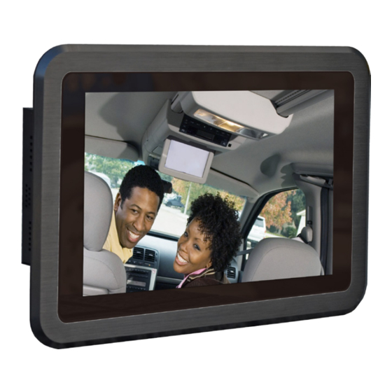
- Page 1 KS310-IMX6 10.1” Touch Panel PC User’s Manual A35830551 Chapter 1 Introduction www.dfi.com...
-
Page 2: Copyright
Product names or trademarks appearing in this manual are for identification purpose only and Shielded interface cables must be used in order to comply with the emission limits. are the properties of the respective owners. Chapter 1 Introduction www.dfi.com... -
Page 3: Table Of Contents
.......................6 MXM Connector ..................29 Key Features ....................6 Specifications ....................7 Chapter 5 - Mounting Options .............. 32 Getting the Know the KS310-IMX6 ............8 Mechanical Dimensions ................9 Wall Mount ....................32 Panel Mount ....................33 Chapter 2 - Installing the Devices ��������������������������������������������... -
Page 4: About This Manual
To reduce the risk of electric shock: • Unplug the power cord before removing the system chassis cover for installation or servic- ing. After installation or servicing, cover the system chassis before plugging the power cord. Battery: • Danger of explosion if battery incorrectly replaced. • Replace only with the same or equivalent type recommend by the manufacturer. • Dispose of used batteries according to local ordinance. Chapter 1 Introduction www.dfi.com... -
Page 5: Safety Precautions
• Disconnect the system from the DC outlet before cleaning. Use a damp cloth. Do not use liquid or spray detergents for cleaning. Chapter 1 Introduction www.dfi.com... -
Page 6: Chapter 1 - Introduction
Chapter 1 Chapter 1 - Introduction Key Features Overview Model Name KS310-IMX6 KS310-IMX6 Processor Freescale i.MX 6 series processor 1 LAN 2 COM Display 1 HDMI 1 USB Client port and 2 USB 2.0/1.1 ports Audio Line-out/Mic-in jack Side View... -
Page 7: Specifications
- Supports PCIe and USB signals - Supports full size Mini PCIe card • 1 mSATA slot (Mini PCIe type) • 1 SIM card socket - Reserved for 3G/LTE module Environment • Temperature - Operating: 0 C ~ 55 - Storage: -30 C ~ 80 • Relative Humidity - 85% RH at 65 Chapter 1 Introduction www.dfi.com... -
Page 8: Getting The Know The Ks310-Imx6
Chapter 1 Getting to Know the KS310-IMX6 Side View Bottom View Line-out/Mic-in DC-in 2 1W built-in speakers HDMI Power Switch 8-bit GPIO USB Client COM Port Used to connect a serial device. USB Ports Used to connect USB 2.0/1.1 devices. -
Page 9: Mechanical Dimensions
Mechanical Dimensions 262.30 15.35 15.35 102.03 97.00 96.07 90.71 Top View 293.00 75.00 75.71 59.52 41.71 39.21 29.94 26.71 24.00 17.00 14.98 Left View Front View Right View 262.30 0.00 15.35 Bottom View 293.00 75.00 Rear View Chapter 1 Introduction www.dfi.com... -
Page 10: Chapter 2 - Installing The Devices
Chapter 2 Chapter 2 - Installing the Devices 2. Plug the terminal block into the DC-in connector and then tighten the screws to secure the terminal block in place. Connecting the Cable to the Terminal Block Note: The system unit used in the following illustrations may not resemble the actual one. DC-in These illustrations are for reference only. -
Page 11: Removing The Chassis Cover
Chapter 2 Removing the Chassis Cover 5. The Mini PCIe slots and SIM card slot are readily accessible after removing the chassis cover. Note: The system unit used in the following illustrations may not resemble the actual one. These illustrations are for reference only. 1. -
Page 12: Installing The Microsd Card And The Qseven Module
Chapter 2 Installing the microSD Card and the Qseven Module 3. Note the key on the MXM connector. The key ensures that the Qseven module with a mi- croSD card in the socket can be plugged into the connector in one direction only. Note: The system unit used in the following illustrations may not resemble the actual one. - Page 13 Chapter 2 5. Press down the Qseven module with a microSD card in the socket and use mounting screws to fix it on place. Mounting screw Chapter 2 Installing the Devices www.dfi .com...
-
Page 14: Chapter 3 - Jumper Settings
Chapter 3 Chapter 3 - Jumper Settings COM RS232/UART5 Select Jumper Settings - System Board Panel Power Select JP12 JP11 1-2 On: RS232 (default) 2-3 On: UART5 JP11 and JP12 are used to configure the COM port to RS232 (default) or UART5. Important: You need to set JP11 and JP12 simultaneously. -
Page 15: Com 1/Com 2 Rs232/422/485 Select
Chapter 3 COM 1/COM 2 RS232/422/485 Select JP4 (for COM 1)/JP6 (for COM 2) 3-4 On: RS422 5-6 On: RS485 1-2 On: RS232 Full Duplex (default) COM 1 COM 1: RS232/422/485 RTS- CTS- COM 1 DSR- TXD- TXD+ DTR- RXD- RXD+ DCD- DATA-... -
Page 16: Touch Panel Power Select
Chapter 3 Touch Panel Power Select Dimming Mode Select JP10 1-2 On: 1-2 On: 2-3 On: +5V_standby 2-3 On: +3V_standby PWM Mode (default) (default) Voltage Mode JP3 controls the power level of the touch panel IC. JP10 allows you to select the mode for the lightness control of the LVDS panel. Important: You need to refer to your panel’s user guide to determine the type of mode (PWM or Voltage) most appropriate for your panel. -
Page 17: Lcd/Inverter Power Select
Chapter 3 LCD/Inverter Power Select Download Mode Select 1-2 On: Serial Download Mode 2-3 On: Normal Boot (default) JP9 allows you to select the download mode for the serial port to update the firmware and OS. 6 4 2 6 4 2 6 4 2 5-6 On: +3V_standby 1-2 On: +12V... -
Page 18: Line-Out/Mic-In Select
Chapter 3 Jumper Setting - Qseven Module Line-out/Mic-in Select Boot Device Select JP7 1-2, 3-4, 5-6 On: JP8 1-2, 3-4, 5-6 On: Line-out Mic-in (default) 2 4 6 JP7 JP8 1 Off, 2 Off, 3 On, 4 On: Switch eMMC 1 Off, 2 Off, 3 On, 4 Off: 1 On, 2 On, 3 Off, 4 On: SPI3 on board SPI... -
Page 19: Chapter 4 - Ports And Connectors
Chapter 4 Chapter 4 - Ports and Connectors SD Card Socket Top Panel I/O Ports The top panel I/O ports consist of the following: • 1 SD card socket • 1 COM port SD Card Socket SD Card Socket This expansion port is used to insert a Secure Digital Input/Output (SDIO) device. Aside from storing data files, an SDIO card is also capable of storing powerful software applications. -
Page 20: Serial (Com) Port
Chapter 4 Side Panel I/O Ports Serial (COM) Port 2 built-in 1W speakers The side panel I/O ports consist of the following: • 2 built-in 1W speakers (left and right sides) COM 2: RS232/422/485 The serial COM port is RS232 asynchronous communication port with 16C550A-compatible Built-in Speakers UARTs that can be used with modems, serial printers, remote display terminals, and other se- rial devices. -
Page 21: Bottom Panel I/O Ports
Chapter 4 Bottom Panel I/O Ports Serial (COM) Port 1 2 3 4 5 Line-out/Mic-in DC-in COM: RS232 or UART5 6 7 8 9 HDMI Power Switch 8-bit GPIO USB Client The bottom panel I/O ports consist of the following: •... -
Page 22: Hdmi Port
Chapter 4 HDMI Port USB Client Port HDMI USB Client The shape of the mini USB port is smaller than the standard one and is a device operating as The HDMI port which carries both digital audio and video signals is used to connect a LCD a client port. -
Page 23: Usb Ports
Chapter 4 USB Ports Audio Line-out/Mic-in USB 2.0 USB 1 USB 0 The USB device allows data exchange between your computer and a wide range of simultane- The system unit is equipped with 1 audio jack to operate as a line-out jack or a mic-in jack. ously accessible external Plug and Play peripherals. -
Page 24: Dc-In
Chapter 4 12~36V DC-in RJ45 LAN Port DC-in The onboard RJ45 LAN port allows the system board to connect to a local area network by This jack is considered a low power solution. Connect a DC power cord to this jack. Use a means of a network hub. -
Page 25: 8-Bit Gpio
DIO_IN-0 Refer to the “Jumper Settings” section in chapter 3 for settings relevant to the LVDS LCD panel. DIO_OUT-1 DIO_IN-1 DIO_OUT-2 DIO_IN-2 Note: DFI board's LVDS connector: Hirose DF13-40DP-1.25V(91)/40P/1.25mm; cable side DIO_OUT-3 DIO_IN-3 connector: Hirose DF13-40DS-1.25C. DIO_OUT-4 DIO_IN-4 DIO_OUT-5 DIO_IN-5 +3.3V... -
Page 26: Flexcan Connector
Chapter 4 FlexCAN Connector The table below illustrates the pin functions of the LVDS LCD Panel connector: Pins Function Pins Function LVDS1_Out3+ LVDS0_Out3+ LVDS0_Out3- LVDS1_Out3- LVDS0_Out2+ LVDS1_Out2+ LVDS0_Out2- LVDS1_Out2- LVDS0_Out1+ LVDS1_Out1+ LVDS0_Out1- LVDS1_Out1- FlexCAN LVDS0_Out0+ LVDS1_Out0+ LVDS0_Out0- LVDS1_Out0- CAN_HI CAN_LO LVDS0_CLK+ LVDS1_CLK+ LVDS0_CLK-... -
Page 27: Expansion Slots
Chapter 4 Expansion Slots LEDs SIM Card Socket Mini PCIe (supports PCIe and USB signals) Mini PCIe SD LED (Supports mSATA signal) Power LED SD Card Socket SD LED Mini PCIe Slot The Mini PCIe socket is used to install a Mini PCIe card. Mini PCIe card is a small form factor The SD LED will light when the SDIO card is inserted into the SD card socket. -
Page 28: Rtc Battery
Chapter 4 RTC Battery Power Switch Power Switch Battery Power_Enable +3.3V Power Switch The power switch is used to power on or power off the system. Connect to the battery connector Battery The RTC Battery powers the real-time clock and CMOS memory. It is an auxiliary source of power when the main power is shut off. -
Page 29: Serial (Com) Port
Chapter 4 Serial (COM) Port MXM Connector COM 1: RS232/422/485 The system board is equipped with a 9-pin connector for connecting an external serial COM port (COM 1). COM port 1 will vary according to JP4’s setting. The serial COM port is RS232 asynchronous communication port with 16C550A-compatible UARTs that can be used with modems, serial printers, remote display terminals, and other se- rial devices. - Page 30 Chapter 4 Signal Signal Signal Signal LVDS_A0- LVDS_B0- LVDS_A1+ LVDS_B1+ GBE_MDI3- GBE_MDI2- LVDS_A1- LVDS_B1- GBE_MDI3+ GBE_MDI2+ LVDS_A2+ LVDS_B2+ GBE_LINK100# GBE_LINK1000# LVDS_A2- LVDS_B2- GBE_MDI1- GBE_MDI0- LVDS_PPEN LVDS_BLEN GBE_MDI1+ GBE_MDI0+ LVDS_A3+ LVDS_B3+ GBE_LINK# GBE_ACT# LVDS_A3- LVDS_B3- SUS_S5# WAKE# SUS_S3# LVDS_A_CLK+ LVDS_B_CLK+ SUS_STAT# PWRBTN# LVDS_A_CLK- LVDS_B_CLK-...
- Page 31 Chapter 4 Signal Signal SPI_MOS0 SPI_SCK MFG_NC4 5V_SB 5V_SB MFG_NC0 MFG_NC2 MFG_NC1 MFG_NC3 VCC (+5V) VCC (+5V) VCC (+5V) VCC (+5V) VCC (+5V) VCC (+5V) VCC (+5V) VCC (+5V) VCC (+5V) VCC (+5V) VCC (+5V) VCC (+5V) VCC (+5V) VCC (+5V) VCC (+5V) VCC (+5V) VCC (+5V)
-
Page 32: Chapter 5 - Mounting Options
Chapter 5 Chapter 5 - Mounting Options 3. Attach the other bracket (wall mount bracket 2) to the rear of the Panel PC. Wall Mount Note: Mounting screw The system unit used in the following illustrations may not resemble the actual one. These illustrations are for reference only. -
Page 33: Panel Mount
Chapter 5 Panel Mount Note: The system unit used in the following illustrations may not resemble the actual one. These illustrations are for reference only. The panel mounting kit includes the following: • 4 mounting clamps Select a place on the panel where you will mount the Panel PC. Cut out a shape on the panel that corresponds to the Panel PC’s rear dimensions (265.3mm x 169mm). - Page 34 Chapter 5 3. Slide the Panel PC through the hole until it is properly fi tted against the panel. 4. Position the mounting clamps along the rear edges of the Panel PC, fi tting them into the slits that are around the Panel PC. Mounting clamp Slit for mounting...
-
Page 35: Chapter 6 - Bsp Installation Guide
Chapter 6 Chapter 6 - BSP Installation Guide 2. Installing the MFG Tool 1. Preparing the Working Environment for the BSP Installation Set the jumper Download Mode Select (JP19) to 1-2: On. • 1 Windows XP/7 32-bit/64-bit • 1 Putty.exe. •... - Page 36 Chapter 6 2. Connect the Mini USB cable and the RS232 cable, and then power-on the system. 3. Burn Bin files and copy Bin files into the content of MFG Tool. 3. Double check if the device is correctly installed. •...
- Page 37 Chapter 6 5. Click “Start“ to burn the file. Putty.exe Chapter 6 BSP User Guide www.dfi .com...
-
Page 38: How To Use The Adb Tool
Chapter 6 3. How to Use the ADB Tool 6. After the burning is done, click “Stop“ and shut down FS700. Set to the “Start Mode“ and then reboot the device into the OS. 1. Install the driver while booting Android. Path: C:\ADB\adb_usb_driver Chapter 6 BSP User Guide www.dfi... - Page 39 Chapter 6 2. Check if the USB debugging in Android is ticked off. If not, click on “Settings”->”Developer 3. Prepare the ADB Tool. options”->“USB debugging”. • Copy the “.android“ content to windows • Path: C:\ADB • XP: copy the “.android“ content to C:\Documents and Settings\“Your PC logging name” •...
- Page 40 Chapter 6 Enter “adb devices.“ When “0123456789ABCDEF“ appears, it means the connection is success- ful. The adb command can be used. 5. adb command • Install APK --> “adb install D:\demo\APK\ ES1.4.8.9.apk” • Close the adb service --> “adb kill-server” •...
Need help?
Do you have a question about the KS310-IMX6 and is the answer not in the manual?
Questions and answers