Advertisement
EC800 Series Installation Guide
• 1 EC800 system unit
• 1 Power adapter: 60W
• 6 mounting screws for Mini PCIe module
• 1 Quick Installation Guide
• 1 CD disk includes:
- Drivers / Manual
DFI reserves the right to change the specifi cations at any time prior to the product's release. For the latest revision and for a
more details of the installation process, please refer to the user's manual on the website.
Package Contents
Panel
LAN 2
LAN 1
HDD LED
Mic-in
COM 1
CFast
Front View
Wi-Fi/3G
Antenna
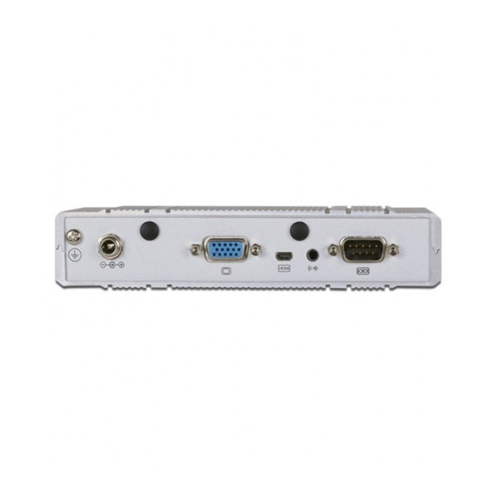
9~24V DC-in
VGA
micro HDMI
Dual Display Rear View
Wi-Fi/3G
Antenna
9~24V DC-in
DVI-I
Single Display Rear View
www.dfi .com
1
Reset
USB
Power
Status LED
Wi-Fi/3G
Antenna
Line-out
COM 2
Wi-Fi/3G
Antenna
Line-out
COM 2/
Isolated 4-bit DIO
Advertisement
Table of Contents

Related Manuals for DFI EC800 Series


Summary of Contents for DFI EC800 Series
-
Page 1: Package Contents
Single Display Rear View DFI reserves the right to change the specifi cations at any time prior to the product's release. For the latest revision and for a more details of the installation process, please refer to the user's manual on the website. -
Page 2: Removing The Chassis Cover
Removing the Chassis Cover 1. Make sure the system and all other peripheral devices connected to it has been powered- off. 2. Disconnect all power cords and cables. 3. The 4 mounting screws on the bottom side (labeled side) of the system are used to secure the cover to the chassis. - Page 3 Installing a Mini PCIe and/or mSATA Card 1. Locate the Mini PCIe slot on the system PCIe x1, USB, board. 3G signal PCIe x1, USB, Wi-Fi signal Full length 2. The system board is equipped with 2 Mini PCIe slots. The Mini PCIe slot supports full length and half length Mini PCIe card.
- Page 4 Board Layout and Jumper Settings Chassis Intrusion Battery Power-on/ CMOS SPI Flash BIOS Select (JP5) System fan HDD_LED Fintek F81866 Mini PCIe 1 mSATA Mini PCIe 2 COM 2/ DIO Select (JP10) SIM Card slot Buzzer COM 2/ DIO Select (JP9) Realtek 9VRS4339 ALC886...
Need help?
Do you have a question about the EC800 Series and is the answer not in the manual?
Questions and answers