Table of Contents
Advertisement
Quick Links
Download this manual
See also:
Installation Manual
Advertisement
Table of Contents

Related Manuals for DFI EC800


Summary of Contents for DFI EC800
- Page 1 EC800 Fanless Embedded System User’s Manual A26050441 Chapter 1 Introduction www.dfi .com...
-
Page 2: Copyright
Copyright FCC and DOC Statement on Class A This publication contains information that is protected by copyright. No part of it may be re- This equipment has been tested and found to comply with the limits for a Class A digital produced in any form or by any means or used to make any transformation/adaptation without device, pursuant to Part 15 of the FCC rules. -
Page 3: Table Of Contents
Cooling Fan Connector ................26 Key Features ....................6 LEDs ......................27 Specifications ....................7 Battery ..................... 27 Getting the Know the EC800 Series ............. 8 Mechanical Dimensions Chapter 6 - Mounting Options ................9 .............. 28 Chapter 2 - Getting Started .............. -
Page 4: About This Manual
About this Manual Static Electricity Precautions An electronic file of this manual is included in the CD. To view the user’s manual in the CD, in- It is quite easy to inadvertently damage your PC, system board, components or devices even sert the CD into a CD-ROM drive. -
Page 5: Safety Precautions
• Unplug the power cord before removing the system chassis cover for installation or servic- ing. After installation or servicing, cover the system chassis before plugging the power cord. • 1 EC800 system unit • 1 Power adapter: 60W • Danger of explosion if battery incorrectly replaced. -
Page 6: Chapter 1 - Introduction
Chapter 1 Chapter 1 - Introduction Overview Key Features EC800 Series Processor Intel ® Atom D2550/N2800/N2600 processors Chipset Intel ® NM10 2 LAN ports 2 COM ports Display DVI-I or VGA and micro HDMI 4 Type A USB 2.0/1.1 ports at the front panel... -
Page 7: Specifications
• Supports RS485 auto direction control Expansion • 3 Mini PCIe slots - 2 slots for communication Rear I/O Ports EC800-CD2040 EC800-CD1440 EC800-CD2041 : One slot supports PCIe x1, USB, and LPC signals for Wi-Fi module or LPC module DC-in power jack... -
Page 8: Getting The Know The Ec800 Series
Chapter 1 Getting to Know the EC800 Series Front View Rear View LAN 2 Reset Wi-Fi/3G Wi-Fi/3G Antenna Antenna Mic-in LAN 1 Power HDD LED with DVI-I 9~24V DC-in DVI-I Line-out CFast Status LED Wi-Fi/3G Wi-Fi/3G USB Ports Antenna Antenna Used to connect USB 2.0/1.1 devices. -
Page 9: Mechanical Dimensions
Chapter 1 Mechanical Dimensions Chassis Dimension Motherboard Dimension 161.00 102.00 98.40 79.32 60.54 58.47 44.21 37.32 Left View Right View 3.20 Front View 0.00 Chapter 1 Introduction www.dfi .com... -
Page 10: Chapter 2 - Getting Started
Chapter 2 Chapter 2 - Getting Started Preparing the System Before you start using the system, you need the following items: • CFast card • AC power adapter • USB keyboard • USB mouse • CD-ROM drive (for installing software/drivers) Installing Devices The following are devices that can be installed in the system. -
Page 11: Chapter 3 - Installing Devices
Chapter 3 Chapter 3 - Installing Devices 5. The CFast socket, and Mini PCIe/mSATA slot are readily accessible after removing the chassis cover. And the SIM slot is also accessible at the side of the system board. Removing the Chassis Cover 1. -
Page 12: Installing A Cfast Card
Chapter 3 Installing a CFast Card Installing a SIM Card 1. Locate the CFast socket on the system board. 1. Locate the SIM slot on the system board. CFast Socket 2. Note the key on the socket. The key ensures the CFast card can be plugged into the socket in SIM slot only one direction. -
Page 13: Installing A Mini Pcie And/Or Msata Card
Chapter 3 Installing a Mini PCIe and/or mSATA card 3. Grasping the Mini PCIe card by its edges, align the card into the slot at an approximately 30 degrees angle. Apply fi rm even pressure to each end of the card until it slips down into the Installing the Mini PCIe Card slot. -
Page 14: Installing Msata Card
Chapter 3 Installing the mSATA Card 3. Grasping the mSATA card by its edges, align the card into the slot at an approximately 30 degrees angle. Apply fi rm even pressure to each end of the card until it slips down into the slot. -
Page 15: Chapter 4 - Jumper Settings
Chapter 4 Chapter 4 - Jumper Settings Power-on/ Clear CMOS 1-3 On: Power-on via 2-4 On: Normal power button (default) (default) 3-5 On: Auto Power-on 4-6 On: Clear CMOS Power-on Clear CMOS JP5 is used to select the method of powering on the system. If you want the system to pow- If you encounter the following, er-on whenever AC power comes in, set JP5 pins 3 and 5 to On. -
Page 16: Usb Power Select
Chapter 4 USB Power Select COM2/DIO Select USB 0-1 USB 2-5 JP9 and JP10 1-4-7-10, 2-5-8-11 On: COM2 (default) 2-4 On: +5V 1-3 On: +5V 3-5 On: +5V_standby 4-6 On: +5V_standby 2-5-8-11, 3-6-9-12 (default) (default) On: DIO These jumpers are used to select the power of the USB ports. Selecting +5V_standby will allow The system board uses JP9 and JP10 to select between RS232/422/485 COM2 or isolated 4-bit you to use a USB device to wake up the system. -
Page 17: Chapter 5 - Ports And Connectors
Chapter 5 Chapter 5 - Ports and Connectors USB Ports Front Panel I/O Ports LAN 2 USB 0-3 LAN 1 Mic-in CFast The front panel I/O port consists of the following: -Data -Data +Data +Data • 4 USB ports • 1 CFast socket N. -
Page 18: Com1 (Serial) Port
Chapter 5 COM1 (Serial) Port Wake-On-USB Keyboard/Mouse The Wake-On-USB Keyboard/Mouse function allows you to use a USB keyboard or USB mouse to wake up a system from the S3 (STR - Suspend To RAM) state. To use this function: • Jumper Setting JP8 must be set to “4-6 On: +5V_standby”. -
Page 19: Cfast Socket
Chapter 5 CFast Socket Mic-in jack Mic-in CFast The CFast socket is used for inserting a CFast card. A CFast card is a small removable mass This jack is used to connect an external microphone. storage device designed with flash technology - a non-volatile storage solution that does not require a battery to retain data indefinitely. -
Page 20: Rj45 Lan Ports
Chapter 5 RJ45 LAN Ports LAN 2 LAN 1 Features • Intel WG82574L PCI Express Gigabit Ethernet controller ® The LAN ports allow the system board to connect to a local area network by means of a net- work hub. BIOS Setting Configure the onboard LAN in the Chipset menu (“South Bridge Configuration”... -
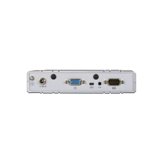
Page 21: Rear Panel I/O Ports
Configure the display device in the Chipset menu (“North Bridge Configuration” submenu) of • 1 RS232/422/485 COM port the BIOS. Refer to chapter 7 for more information. • 1 Line-out jack Driver Installation Rear I/O Ports EC800- EC800- EC800- EC800- CD2040-2x2 CD1440-2x2... -
Page 22: Vga Port
Chapter 5 VGA Port micro HDMI Port micro HDMI The VGA port is used for connecting a VGA monitor. Connect the monitor’s 15-pin D-shell cable The HDMI port which carries both digital audio and video signals is used to connect a LCD connector to the VGA port. -
Page 23: Dc-In
Chapter 5 DC-in Line-out jack Line-out This jack provides maximum of 60W power and is considered a low power solution. Connect This jack is used to connect a headphone or external speakers. a DC power cord to this jack. Use a power adapter within 9~24V DC output voltage. Using a voltage range out of 9~24V may fail to boot the system or cause damage to the system board. -
Page 24: Com2 (Serial) Port/ Isolated 4-Bit Dio
Chapter 5 COM2 (Serial) Port/ Isolated 4-bit DIO RS232/422/485 COM2 or Isolated 4-bit DIO COM 2 1 2 3 4 5 1 2 3 4 5 1 2 3 4 5 RS232 RS422 RS485 Full Duplex This DB-9 port can be used as an RS232/422/485 COM port or as an isolated 4-bit DIO. Refer COM2 Function to the jumper setting in this section for its respective configuration. -
Page 25: I/O Connectors
Chapter 5 I/O Connectors Expansion Slots SIM slot Mini PCIe slot for Mini PCIe slot for Digital I/O Connector PCIe x1, USB, and 3G PCIe x1, USB, and Wi-Fi signals signals Mini PCIe for mSATA 4-bit in and 4-bit out DIO with power The 4-bit in and 4-bit out Digital I/O connector provides powering-on function to external de- vices that are connected to these connectors. -
Page 26: Chassis Intrusion Connector
Chapter 5 Chassis Intrusion Connector Cooling Fan Connector Ground Ground Sense Power Signal System fan The board supports the chassis intrusion detection function. Connect the chassis intrusion The fan connectors are used to connect cooling fans. The cooling fans will provide adequate sensor cable from the chassis to this connector. -
Page 27: Leds
Chapter 5 LEDs Battery HDD LED Battery Ground Battery Standby Power LED Standby Power LED This LED will blink when the system is in the standby mode. It indicates that there is power on the system board. Power-off the PC and then unplug the power cord prior to installing any devices. -
Page 28: Chapter 6 - Mounting Options
Chapter 6 Chapter 6 - Mounting Options 2. At the bottom side of the system, use the provided mounting screws to secure the wallmount brackets on each side of the system. Wall Mount Mounting screw The wall mount kit includes the following: •... -
Page 29: Vesa Mount
• 2 VESA mount bracket B • Bracket screws Mounting Screw EC800 VESA bracket A VESA bracket B 1. Prior to installing the VESA mount bracket A, make sure you have already installed the VESA mount bracket B. 2. Used the provided mounting screws to secure the VESA bracket A in place. - Page 30 1 DIN Rail mount bracket • 1 bracket • Bracket screws EC800 Bracket EC800 1. Turn the system to the bottom side (labeled side) and top side and locate the mounting Bracket screw. Remove these screws and then put them in a safe place for later use.
- Page 31 Chapter 6 4. Align the mounting holes of the bracket in the system and the mounting holes on the DIN rail bracket, and then use the provided mounting screws to secure the bracket in place. DIN Rail bracket Mounting Screw Bracket Chapter 6 Mounting Options www.dfi...
-
Page 32: Chapter 7 - Bios Setup
Chapter 7 Chapter 7 - BIOS Setup Legends Overview Keys Function The BIOS is a program that takes care of the basic level of communication between the CPU and peripherals. It contains codes for various advanced features found in this system board. Moves the highlight left or right to select a menu. -
Page 33: Ami Bios Setup Utility
Security Save & Exit Compliency UEFI 2.3; PI 1.2 Project Version 1APJK 0.15.013 x64 Legacy OpROM Support F81866A WDT Parameters. Model Name DFI-CD952 Launch PCI-E NIC PXE [Disabled] Bios Name CD9520C5.28A Launch I82574 WOL [Disabled] Bios Version RA07 Launch Resume on Ring... - Page 34 Chapter 7 PCI Subsystem Settings ACPI Power Management Configuration This section is used to configure the PCI Subsystem. This section is used to configure the ACPI Setting. Aptio Setup Utility - Copyright (C) 2012 American Megatrends, Inc. Aptio Setup Utility - Copyright (C) 2012 American Megatrends, Inc. Advanced Advanced ACPI Power Management Confi...
- Page 35 Chapter 7 CPU Configuration IDE Configuration This section is used to configure the CPU. It will also display the detected CPU This section is used to configure IDE functions. information. Aptio Setup Utility - Copyright (C) 2012 American Megatrends, Inc. Advanced Aptio Setup Utility - Copyright (C) 2012 American Megatrends, Inc.
- Page 36 Chapter 7 USB Configuration Super IO Configuration This section is used to configure USB. This section is used to configure the I/O functions supported by the onboard Super I/O chip. Aptio Setup Utility - Copyright (C) 2012 American Megatrends, Inc. Aptio Setup Utility - Copyright (C) 2012 American Megatrends, Inc.
- Page 37 Chapter 7 Serial Port 1 Configuration to Serial Port 2 Configuration PC Health Status This section displays the hardware health monitor. Aptio Setup Utility - Copyright (C) 2012 American Megatrends, Inc. Advanced Aptio Setup Utility - Copyright (C) 2012 American Megatrends, Inc. Serial Port 1 Confi...
- Page 38 Chapter 7 PPM Configuration WatchDog Configuration This section is used to configure the PPM functions. This section is used to configure the watchdog functions. Aptio Setup Utility - Copyright (C) 2012 American Megatrends, Inc. Aptio Setup Utility - Copyright (C) 2012 American Megatrends, Inc. Advanced Advanced Enable/Disable F81866...
- Page 39 Chapter 7 Chipset Host Bridge Configures relevant chipset functions. Aptio Setup Utility - Copyright (C) 2012 American Megatrends, Inc. Chipset Select the Video Device Aptio Setup Utility - Copyright (C) 2012 American Megatrends, Inc. Intel IGD Confi guration which will be activated IGFX - Boot Type [VBIOS Default] Main...
- Page 40 Chapter 7 South Bridge TPT Devices Enable or disable Intel IO Controller Hub (TPT) devices Aptio Setup Utility - Copyright (C) 2012 American Megatrends, Inc. Chipset Aptio Setup Utility - Copyright (C) 2012 American Megatrends, Inc. Enable/ Disable Intel (R) ...
- Page 41 Chapter 7 PCI Express Root Port 0~3 This section is used to configure the PCI Express Root functions. Aptio Setup Utility - Copyright (C) 2012 American Megatrends, Inc. Advanced [Enabled] PCI Express Port 0 Enable/Disable Intel SpeedStep Select Screen ...
- Page 42 Chapter 7 Boot Security Aptio Setup Utility - Copyright (C) 2012 American Megatrends, Inc. Aptio Setup Utility - Copyright (C) 2012 American Megatrends, Inc. Main Advanced Chipset Boot Security Save & Exit Main Advanced Chipset Boot Security Save & Exit Boot Confi...
-
Page 43: Updating The Bios
Chapter 7 Save & Exit Updating the BIOS To update the BIOS, you will need the new BIOS file and a flash utility, AFUDOS.EXE. Aptio Setup Utility - Copyright (C) 2012 American Megatrends, Inc. Please contact technical support or your sales representative for the files. Main Advanced Chipset... -
Page 44: Chapter 8 - Supported Software
Chapter 8 Chapter 8 - Supported Software Auto Run Page (For Windows 7) The CD that came with the system board contains drivers, utilities and software applications required to enhance the performance of the system board. Insert the CD into a CD-ROM drive. The autorun screen (Mainboard Utility CD) will appear. If after inserting the CD, “Autorun”... - Page 45 Chapter 8 Microsoft .NET Framework 3.5 (For Windows XP only) 3. Click Exit. Note: Before installing Microsoft .NET Framework 3.5, make sure you have updated your Windows XP operating system to Service Pack 3. To install the driver, click “Microsoft .NET Framework 3.5” on the main menu. 1.
- Page 46 Chapter 8 Microsoft DirectX 9.0C (For Windows XP only) Intel Chipset Software Installation Utility (For Windows XP) To install the utility, click “Microsoft DirectX 9.0C Driver” on the main menu. The Intel Chipset Software Installation Utility is used for updating Windows INF files so that ®...
- Page 47 Chapter 8 Intel Chipset Software Installation Utility 3. Go through the readme document for system (For Windows 7) requirements and installation tips then click Next. The Intel Chipset Software Installation Utility is used for updating Windows INF files so that ®...
- Page 48 Chapter 8 Intel Graphics Drivers (For Windows XP) 3. Go through the readme document for system re- quirements and installation To install the driver, click “Intel Graphics Drivers” on the main menu. tips then click Next. 1. Setup is now ready to install the graphics driver.
- Page 49 Chapter 8 Intel Graphics Drivers (For Windows 7) 4. Setup is now installing the driver. To install the driver, click “Intel Graphics Drivers” on the main menu. 1. Setup is now ready to install the graphics driver. Click Next. 5. Click “Yes” to restart this computer now.
- Page 50 Chapter 8 Audio Drivers (For Windows XP) 3. Go through the readme docu- ment for system requirements and installation tips then click To install the driver, click “Audio Drivers” on the main menu. Next. 1. Setup is now ready to install the audio driver.
- Page 51 Chapter 8 Audio Drivers (For Windows 7) Intel LAN Drivers (For Windows XP) To install the driver, click “Audio Drivers” on the main menu. To install the driver, click “Intel LAN Drivers” on the main menu. 1. Setup is ready to install the 1.
- Page 52 Chapter 8 Intel LAN Drivers (For Windows 7) 4. Click Install to begin the installation. To install the driver, click “Intel LAN Drivers” on the main menu. 1. Setup is ready to install the driver. Click Next. 5. After completing installa- tion, click Finish.
- Page 53 Chapter 8 Intel Rapid Storage Technology 4. Click Install to begin the installation. The Intel Rapid Storage Technology is a utility that allows you to monitor the current status of the SATA drives. It enables enhanced performance and power management for the storage subsystem.
- Page 54 Chapter 8 3. Read the license agreement then 6. Click “Yes, I want to restart my click Yes. computer now” then click Finish. Restarting the system will allow the new software installation to take effect. 4. Go through the readme document 7.
- Page 55 DFI Utility This is used to create a floppy driver diskette needed when you install Windows DFI Utility provides information about the board, Watchdog, DIO, and Backlight. ® XP using the F6 installation method. This will allow you to install the operating To access the utility, click “DFI Utility”...
- Page 56 Chapter 8 3. Enter “User name” and “Organization” information then click “Next”. 4. Click “Install” to begin the installation. 5. After completing installa tion, click “Finish”. Chapter 8 Supported Software www.dfi .com...
- Page 57 Chapter 8 Adobe Acrobat Reader 9.3 To install the reader, click “Adobe Acrobat Reader 9.3” on the main menu. 1. Click Next to install or click Change Destination Folder to select another folder. 2. Click Install to begin installa- tion. 3.
-
Page 58: Appendix A - Watchdog Sample Code
Appendix A Appendix A - Watchdog Sample Code ;Software programming example: ;--------------------------------------------- ;(1) Enter Super IO Confi guration mode ;--------------------------------------------- DX,2EH AL,87H DX,AL DX,AL ;------------------------------------------------------------------------------------------- ;(2) Confi guration Logical Device 7, register CRF5/CRF6 (WDT Control /WDT timer) ;------------------------------------------------------------------------------------------- DX,2EH AL,07H ;Ready to Program Logical Device DX,AL DX,2FH... -
Page 59: Appendix B - System Error Message
Appendix B Appendix B - System Error Message Hard Disk(s) fail (20) When the BIOS encounters an error that requires the user to correct something, either a beep HDD initialization error. code will sound or a message will be displayed in a box in the middle of the screen and the message, PRESS F1 TO CONTINUE, CTRL-ALT-ESC or DEL TO ENTER SETUP, will be shown in Hard Disk(s) fail (10) the information box at the bottom. -
Page 60: Appendix C - Troubleshooting Checklist
Appendix C Appendix C - Troubleshooting Checklist The picture seems to be constantly moving. Troubleshooting Checklist 1. The monitor has lost its vertical sync. Adjust the monitor’s vertical sync. 2. Move away any objects, such as another monitor or fan, that may be creating a magnetic This chapter of the manual is designed to help you with problems that you may encounter field around the display. -
Page 61: System Board
Appendix C Hard Drive System Board 1. Make sure the add-in card is seated securely in the expansion slot. If the add-in card is Hard disk failure. loose, power off the system, re-install the card and power up the system. 1. -
Page 62: Appendix D - Exploded Diagram
Appendix D Appendix D - Exploded Diagram 531-510750-000G A31-027014-200G A33-630019-A70G A31-025011-200G A71-210010-000G A52-035008-000G PCBA-CD952 A33-530019-070G A31-027009-200G A31-023023-200G Appendix D Exploded Diagram www.dfi .com... -
Page 63: Appendix E - Digital I/O User Guide
CD952 Series: Isolated 8-bit Digital I/O Pin Define IL max: 50mA For example: DIN= 5V RL= 500Ω IL= 1mA DFI DIO DIN1 Utility D0 4-bit in and 4-bit out DIO with power Set DIO at Input Mode The 4-bit in and 4-bit out Digital I/O connector provides powering-on function to external de- vices that are connected to these connectors. - Page 64 Example1 OUT1 to Low. Example2 OUT1 to High. VL: 60V max IL max: 600mA For example: VL= 5V RL= 1KΩ IL= 5mA DFI DIO OUT1 Utility D4 DOUT Example2 with Dout0A/Dout0B According DIO pin to GPIO Programming Setting Pins Function DIN0A...
- Page 65 Appendix E DOUT MAP Pins Function DOUT0A Couple for GPIO 84 DOUT0B DOUT1A Couple for GPIO 85 DOUT1B DOUT2A Couple for GPIO 86 DOUT2B DOUT3A Couple for GPIO 87 DOUT3B +5V_standby DIN MAP Appendix E Digital I/O User Guide www.dfi .com...
- Page 66 Appendix E Digital I/O Proramming Guide 3. Relative Registers 1. Pins for Digital I/O Item Standard GPIO80 (Pin111) GP80 GPIO81 (Pin112) GP81 GPIO82 (Pin113) GP82 GPIO83 (Pin114) GP83 GPIO84 (Pin115) GP84 GPIO85 (Pin116) GP85 GPIO86 (Pin117) GP86 GPIO87 (Pin118) GP87 GPIO71 (Pin104) CTR-GP71 GPIO72 (Pin105)
- Page 67 Appendix E Appendix E Digital I/O User Guide www.dfi .com...
- Page 68 Appendix E 4. Sample Code in C Language 4.2 Control of GP80 to GP87 4.1 Control of GP03, GP02 and GP07 #define AddrPort 0x2E #define DataPort 0x2F #define AddrPort 0x2E <Enter the Extended Function Mode> #define DataPort 0x2F WriteByte(AddrPort, 0x87) WriteByte(AddrPort, 0x87) //Must write twice to entering <Enter the Extended Function Mode>...
- Page 69 Appendix E CD952 Series: Isolated 4-bit Digital I/O Jumper Setting CD952 Series: Isolated 4-bit Digital I/O Pin Define COM2/DIO Select COM2 (Serial) Port/ Isolated 4-bit DIO RS232/422/485 COM2 or Isolated 4-bit DIO JP9/JP10 COM port mode 1-4-7-10, 2-5-8-11 On: COM2 (default) Pins DIO Function DIN0A...
- Page 70 Appendix E Isolated 4-bit Digital I/O Input Request Pins Input Request 5V~12V 5V~12V AC or DC Loading AC or DC 5V~60V Load AC or DC Loading AC or DC 5V~60V Load ABSOLUTE MAXIMUM RATINGS SPECIFICATION *Pin1/Pin3 : - Diode forward current(DC) rating IF =50mA/ch. *Pin6/Pin8 : - MOS FET Continuous Load Current rating IL =600mA.
- Page 71 Pins Input Request 5V~12V Pin 1 and 2 are couple, DIN1 5V~12V Pin 3 and 4 are couple, DIN2 DFI DIO OUT1 Utility D4 AC or DC Pin 6 and 7 are Loading AC or DC 5V~60V Load couple, OUT1...
- Page 72 Appendix E DOUT Example3 with Dout1A/Dout1B Set DIO at Output Mode, Press D5 to H Example3 OUT2 to Low. Example4 OUT2 to High. DFI DIO OUT2 Utility D5 DOUT Example4 with Dout1A/Dout1B DIN Example1 with DIN0A/DIN0B IL max: 50mA For example: DIN= 5V RL= 500Ω...
- Page 73 Appendix E Set DIO at Input Mode Set DIO at Input Mode Example1 DIN1= 5V D0 to L Example2 DIN2= 5V D1 to L DIN Example1 with DIN1A/DIN1B DFI DIO OUT2 Utility D1 Appendix E Digital I/O User Guide www.dfi .com...
Need help?
Do you have a question about the EC800 and is the answer not in the manual?
Questions and answers