
Related Manuals for DFI ST101-CR


Summary of Contents for DFI ST101-CR
- Page 1 ST101-CR Desktop Box PC User’s Manual A25700301 Chapter 1 Introduction www.dfi.com...
-
Page 2: Copyright
The changes or modifications not expressly approved by the party responsible for compli- ance could void the user’s authority to operate the equipment. Shielded interface cables must be used in order to comply with the emission limits. Chapter 1 Introduction www.dfi.com... -
Page 3: Table Of Contents
Overview �������������������������������������������������������������������������������������������������������6 Expansion Slots ����������������������������������������������������������������������������������������� 31 Key Features ������������������������������������������������������������������������������������������������6 Battery ����������������������������������������������������������������������������������������������������� 32 Specifications �����������������������������������������������������������������������������������������������7 Getting the Know the ST101-CR ����������������������������������������������������������� 8 Chapter 6 - Mounting Options �������������������������������������������������������������� 33 Mechanical Dimensions ����������������������������������������������������������������������������� 9 Wall Mount ������������������������������������������������������������������������������������������������� 33 Chapter 2 - Getting Started ��������������������������������������������������������... -
Page 4: About This Manual
To reduce the risk of electric shock: • Unplug the power cord before removing the system chassis cover for installation or servic- ing. After installation or servicing, cover the system chassis before plugging the power cord. Battery: • Danger of explosion if battery incorrectly replaced. • Replace only with the same or equivalent type recommend by the manufacturer. • Dispose of used batteries according to local ordinance. Chapter 1 Introduction www.dfi.com... -
Page 5: Safety Precautions
• Unplug the power cord before removing the system chassis cover for installation or servic- ing. After installation or servicing, cover the system chassis before plugging the power cord. • 1 ST101-CR system unit • 1 75W power adapter • Danger of explosion if battery incorrectly replaced. -
Page 6: Chapter 1 - Introduction
Chapter 1 Chapter 1 - Introduction Key Features Overview ST101-CR ® PROCESSOR 3rd/2nd Generation Intel Core processors ® CHIPSET Intel HM76 2 LAN ports 2 COM ports (1 optional) DISPLAYS 1 DVI-I, 1 HDMI 4 USB 3.0; 4 USB 2.0/1.1 ports AUDIO Mic-in/Center+Subwoofer, Line-in/Surround, Line-out Chapter 1 Introduction www.dfi.com... -
Page 7: Specifications
- 1 HDD LED - 1 Power LED - 1 Power button • Rear Panel - 2 DB-9 COM - 1 HDMI - 1 DVI-I - 2 LAN - 2 USB 2.0 - 4 USB 3.0 - Mic-in/Center+Subwoofer, Line-in/Surround, Line-out - 12V DC-in Chapter 1 Introduction www.dfi.com... -
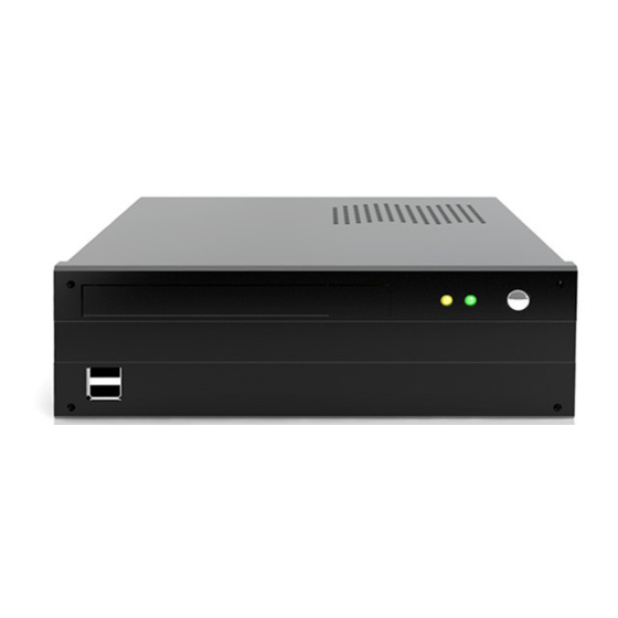
Page 8: Getting The Know The St101-Cr
Chapter 1 Getting to Know the ST101-CR Front View Bottom View Power LED LAN 1 Mic-in/Center+Subwoofer HDD LED USB 2.0 DVI-I LAN 2 Power COM 2 (optional) Line-in/ Surround COM 1 HDMI USB 3.0 DC-in USB 2.0 Optical drive bay (optional) -
Page 9: Mechanical Dimensions
Chapter 1 Mechanical Dimensions Chassis Dimensions Motherboard Dimensions 10.16 10.16 Rear View 0.00 22.86 46.94 47.01 98.01 113.73 70.10 219.00 Left View Right View 132.40 154.94 154.94 160.02 160.02 Front View Chapter 1 Introduction www.dfi.com... -
Page 10: Chapter 2 - Getting Started
Installing the Drivers The system package includes a CD disk. The CD includes drivers that must be installed to pro- vide the best system performance. Refer to the Supported Software chapter for instructions on installing the drivers. Chapter 2 Getting Started www.dfi.com... -
Page 11: Chapter 3 - Installing Devices
4. Lift the cover by first pulling it backward (1) then lifting it up (2). 2. The 4 screws are used to secure the drive bay bracket. Remove these screws and put them in a safe place for later use. Top View Side View Side View Chapter 3 Installing Devices www.dfi.com... -
Page 12: Installing The Sata And Optical Drive Bays
While holding the SATA drive in place, turn the drive bay bracket to the top side then adjust the drive so that the mounting holes on the drive match the mounting holes on the bracket. Now secure the drive by fastening 4 screws. Mounting screw Chapter 3 Installing Devices www.dfi.com... - Page 13 4. After removing the drive bay cover, on the top side of the bracket, position the optical drive as shown below. SATA connector SATA connector Rear view of the optical drive SATA power cable For SATA drive SATA data cable Chapter 3 Installing Devices www.dfi.com...
- Page 14 8. Connect the SATA data cable and SATA power cable (from the system board) to their respective 10. Connect the cable for DVD-ROM to the SATA data and power connectors at the rear of the connectors at the rear of the SATA drive. optical drive. SATA data cable SATA power cable Chapter 3 Installing Devices www.dfi.com...
- Page 15 15. When you power up the system, configure the drives in the BIOS. Refer to the system board manual in the provided DVD. 16. Refer to the manual or documentation enclosed with the drives for additional information on using the drive. Chapter 3 Installing Devices www.dfi.com...
-
Page 16: Chapter 4 - Jumper Settings
2. Set JP10 pins 2 and 3 to On. Wait for a few seconds and set JP10 back to its default set- ting, pins 1 and 2 On. 3. Now plug the power cord and power-on the system. Chapter 4 Jumper Settings www.dfi.com... -
Page 17: Panel Power Select
(default) COM 1 1 2 3 4 5 1 2 3 4 5 1 2 3 4 5 6 7 8 9 6 7 8 9 6 7 8 9 RS422 RS232 RS485 Full Duplex Chapter 4 Jumper Settings www.dfi.com... -
Page 18: Com1/Com2 Rs232 Power Select
VCC12 (+12V) JP3 (for COM 1) is used to configure pin 1 and pin 9 signal of the COM port. The pin function of the COM ports will vary according to the jumper’s setting. Chapter 4 Jumper Settings www.dfi.com... -
Page 19: Power-On Select
The BIOS fields are in the “South Bridge Configuration” submenu (Chipset menu) of the AMI BIOS utility. To power-on via AC Power: 1. Set JP12 pins 2 and 3 to On. 2. Set the “After G3” field to Power On. Chapter 4 Jumper Settings www.dfi.com... -
Page 20: Switch
Chapter 4 Switch 1-2 Off: One PCIe x16(default) 1 On, 2 Off: Two PCIe x8 1-2 On: One PCIe x8, Two PCIe x4 SW1 is used to configure the PCIe x16 slot. Chapter 4 Jumper Settings www.dfi.com... -
Page 21: Chapter 5 - Ports And Connectors
The Wake-On-USB Keyboard/Mouse function allows you to use a USB keyboard or USB mouse to wake up a system from the S3 (STR - Suspend To RAM) state. To use this function: • Jumper Setting JP7 must be set to “2-3 On: +5V_standby”. Refer to “USB Power Select” in this chapter for more information. Important: If you are using the Wake-On-USB Keyboard/Mouse function for 2 USB ports, the +5V_standby power source of your power supply must support ≥1.5A. For 3 or more USB ports, the +5V_standby power source of your power supply must support ≥2A. Chapter 5 Ports and Connectors www.dfi.com... -
Page 22: Rear Panel I/O Ports
The rear panel I/O ports consist of the following: • 1 DC-in • 2 LAN ports • 2 USB 2.0 ports • 4 USB 3.0 ports • 1 DVI-I port • 1 HDMI port • 2 RS232/422/485 COM ports (1 optional) • 1 Line-in/Surround jack • 1 Line-out jack • 1 Mic-in/Center+Subwoofer jack Chapter 5 Ports and Connectors www.dfi.com... -
Page 23: Com (Serial) Ports
Configure the serial ports in the Advanced menu (“Super IO Configuration” submenu) of the BIOS. Refer to chapter 8 for more information. BIOS Setting Configure the display device in the Chipset menu (“North Bridge Configuration” submenu) of the BIOS. Refer to chapter 3 for more information. Chapter 5 Ports and Connectors www.dfi.com... -
Page 24: Rj45 Lan Ports
Configure the onboard USB in the Advanced menu (“USB Configuration” submenu) of the BIOS. Refer to chapter 3 for more information. Driver Installation You may need to install the proper drivers in your operating system to use the USB device. Refer to your operating system’s manual or documentation for more information. Chapter 5 Ports and Connectors www.dfi.com... -
Page 25: Audio
BIOS Setting Configure the onboard audio in the Chipset menu (“South Bridge” submenu) of the BIOS. Refer to chapter 7 for more information. Driver Installation Install the audio driver. Refer to chapter 8 for more information. Chapter 5 Ports and Connectors www.dfi.com... -
Page 26: I/O Connectors
The Serial ATA connectors are used to connect Serial ATA devices. Connect one end of the Se- rial ATA cable to a SATA connector and the other end to your Serial ATA device. BIOS Setting Configure the Serial ATA drives in the Advanced menu (“IDE Configuration” submenu) of the BIOS. Refer to chapter 7 for more information. Chapter 5 Ports and Connectors www.dfi.com... -
Page 27: Lvds Lcd Panel Connectors
LVDS_CLK1- LVDS_CLK2- Configure the LCD panel in the Advanced Chipset Features submenu of the BIOS. Refer to chapter 7 for more information. LVDS_DDCCLK N.C. LVDS_DDCDAA N.C. Panel Power Panel Power Panel Power Panel Power Chapter 5 Ports and Connectors www.dfi.com... -
Page 28: Chassis Instrusion Connector
When enabled, a warning message will appear when the chassis is open. The utility can also be configured so that a beeping alarm will sound when the chassis is open. Refer to the “MyGuard Hardware Monitor” section in chapter 7 for more information. Chapter 5 Ports and Connectors www.dfi.com... -
Page 29: Standby Power Led
(CPU power, amount of memory, add-in cards, peripherals, etc.) may exceed the minimum power requirement. To ensure that adequate power is provided, we strongly recom- mend that you use a minimum of 400 Watt (or greater) power supply. Important: Insufficient power supplied to the system may result in instability or the add-in boards and peripherals not functioning properly. Calculating the system’s approximate power usage is important to ensure that the power supply meets the system’s consumption requirements. Chapter 5 Ports and Connectors www.dfi.com... -
Page 30: Front Panel Connectors
This switch is used to power on or off the system. Connect to storage devices PWR-LED - Power/Standby LED When the system’s power is on, this LED will light. When the system is in the S1 (POS - Power On Suspend) state, it will blink every second. When the system is in the S3 (STR - Suspend To RAM) state, it will blink every 4 seconds. Pin Pin Assignment Pin Pin Assignment HDD Power LED Power HDD-LED Signal PWR-LED LED Power Ground Signal RESET SW PWR-BTN RST Signal Ground N.C. Signal Chapter 5 Ports and Connectors www.dfi.com... -
Page 31: Lpc Connector
LPC bus is implemented over a 4 bit serialized data interface, which uses a 33MHz LPC bus clock. For more information about LPC bus refer to the Intel Low Pin Count Interface ® Specification Revision 1.1’. Chapter 5 Ports and Connectors www.dfi.com... -
Page 32: Battery
The lithium ion battery powers the real-time clock and CMOS memory. It is an auxiliary source of power when the main power is shut off. Safety Measures • Danger of explosion if battery incorrectly replaced. • Replace only with the same or equivalent type recommend by the manufacturer. • Dispose of used batteries according to local ordinance Chapter 5 Ports and Connectors www.dfi.com... -
Page 33: Chapter 6 - Mounting Options
Please refer to the provided DVD for details relevant to the system board. 2. The mounting holes are located at the bottom of the system. Mount the wall mount brackets on each side of the system using the mounting screws. Wall mount bracket Wall mount bracket Chapter 6 Mounting Options www.dfi.com... - Page 34 Chapter 6 4.00 17.50 219.00 Ø10.00 6.00 234.00 249.00 Chapter 6 Mounting Options www.dfi.com...
-
Page 35: Chapter 7 - Bios Setup
“Press DEL to run setup” will appear on the screen. If the message disappears before you respond, restart the system or press the “Reset” button. You may also restart the system by pressing the <Ctrl> <Alt> and <Del> keys simultaneously. Chapter 7 BIOS Setup www.dfi.com... -
Page 36: Ami Bios Setup Utility
The time format is <hour>, <minute>, <second>. The time is based on the 24-hour military-time clock. For example, 1 p.m. is 13:00:00. Hour displays hours from 00 to 23. Minute displays minutes from 00 to 59. Second displays seconds from 00 to 59. Chapter 7 BIOS Setup www.dfi.com... - Page 37 Version 2.14.1219. Copyright (C) 2011 American Megatrends, Inc. CPU Smart Fan Control When this feature is set to Automatic, the CPU’s fan speed will rotate according to the CPU’s temperature. The higher the temperature, the faster the speed of rotation. Chapter 7 BIOS Setup www.dfi.com...
- Page 38 3 or less than 3. Intel Virtualization Technology When this field is set to Enabled, the VMM can utilize the additional hardware capabilities provided by Vanderpool Technology. Chapter 7 BIOS Setup www.dfi.com...
- Page 39 Enter PCH to aggressively enter link power state. This option allows the Serial ATA devices to use AHCI (Advanced Host Controller Inter- face). SATA Test Mode This field is used to enable or disable the Serial ATA test mode. Chapter 7 BIOS Setup www.dfi.com...
- Page 40 Disables support for legacy when no USB devices are connected. Disabled Keeps USB devices available only for EFI applications. EHCI Hand-off This is a workaround for OSes that does not support EHCI hand-off. The EHCI ownership change should be claimed by the EHCI driver. Chapter 7 BIOS Setup www.dfi.com...
- Page 41 “Auto” uses default value: for a Root port it is 100 ms, for a Hub port the delay is taken from Hub descriptor. Select Screen → ←: Select Item ↑↓: Enter: Select +/ -: Change Opt. General Help Previous Values Optimized Defaults ESC: Exit Version 2.14.1219. Copyright (C) 2011 American Megatrends, Inc. Chapter 7 BIOS Setup www.dfi.com...
- Page 42 If the system’s power is on when AC power failure occurs, the system will power-on when power returns. Watchdog Timer Enable or disable Super I/O watchdog timer. Chapter 7 BIOS Setup www.dfi.com...
- Page 43 Version 2.14.1219. Copyright (C) 2011 American Megatrends, Inc. Version 2.14.1219. Copyright (C) 2011 American Megatrends, Inc. Serial Port Enables or disables the serial port. Change Settings Selects the IO/IRQ setting of the I/O device. Device Mode Enable or disable serial port (COM) Chapter 7 BIOS Setup www.dfi.com...
-
Page 44: Chipset
Long Duration Maintained Time window which the long duration power is maintained. Short Duration Power Limit Short duration power limit in Watts, 0 means use factory default. ACPI T State Enable or disable ACPI T state support. Chapter 7 BIOS Setup www.dfi.com... - Page 45 PCI Express Root Port 1 to PCI Express Root Port 3 After G3 Controls the PCI Express Root Port. Power Off / WOL Power-on the system via WOL after G3. Power On Power-on the system after G3. Chapter 7 BIOS Setup www.dfi.com...
- Page 46 Azalia internal HDMI codec Mode of operation of xHCI controller. Options are Smart Auto, Auto, Enabled, Enables or disable the Azalia internal HDMI codec. Disabled. EHCI1 and EHCI2 These fields are used to enable or disable USB 2.0. Chapter 7 BIOS Setup www.dfi.com...
- Page 47 Version 2.14.1219. Copyright (C) 2011 American Megatrends, Inc. DVMT Total Gfx Mem Enabled PEG This field is used to select the graphics memory size used by DVMT mode. To enable or disable the PEG. Chapter 7 BIOS Setup www.dfi.com...
-
Page 48: Boot
Has no effect for BBS boot options. GateA20 Active Upon Request- GA20 can be disabled using BIOS services. Alwasy- Do not allow disabling GA20; this option is useful when any RT code is executed above 1MB. Chapter 7 BIOS Setup www.dfi.com... - Page 49 Enter: Select +/ -: Change Opt. General Help Previous Values Optimized Defaults ESC: Exit Version 2.14.1219. Copyright (C) 2011 American Megatrends, Inc. Launch Storage OpROM policy Controls the execution of UEFI and legacy storage OpROM. Chapter 7 BIOS Setup www.dfi.com...
-
Page 50: Security
Select Yes to save values as user default. Restore User Defaults To restore user default to all the setup options, select this field and then press <Enter>. A dialog box will appear. Select Yes to restore user default. Chapter 7 BIOS Setup www.dfi.com... -
Page 51: Updating The Bios
Copyright (C)2008 American Megatrends Inc. All Rights Reserved. +--------------------------------------------------------------------------------------------------------+ Reading file ......done Erasing flash ......done Writing flash ......done Verifying flash ......done Erasing BootBlock ....done Writing BootBlock ....done Verifying BootBlock ....done C:\AFU\AFUDOS> Chapter 7 BIOS Setup www.dfi.com... -
Page 52: Chapter 8 - Supported Software
Insert the CD into a CD-ROM drive. The autorun screen (Mainboard Utility CD) will appear. If after inserting the CD, “Autorun” did not automatically start (which is, the Mainboard Utility CD screen did not appear), please go directly to the root directory of the CD and double-click “Setup”. Chapter 8 Supported Software www.dfi.com... - Page 53 To install the driver, click “Microsoft .NET Framework 3.5” on the main menu. 1. Read the license agreement carefully. Click “I have read and accept the terms of the License Agreement” then click Install. 2. Setup is now installing the driver. Chapter 8 Supported Software www.dfi.com...
-
Page 54: Intel Chipset Software Installation Utility
To install the utility, click “Intel Chipset Software Installation Utility” on the main menu. 1. Setup is ready to install the utility. Click Next. 4. Click Finish to exit setup. 2. Read the license agreement then click Yes. Chapter 8 Supported Software www.dfi.com... - Page 55 “blank screen” period is the time Windows is testing the graphics perfor- mance. 2. Read the license agreement then click Yes. 5. Click “Yes, I want to restart this computer now” then click Finish. Restarting the system will allow the new software installation to take effect. Chapter 8 Supported Software www.dfi.com...
- Page 56 1. Setup is now ready to install the utility. Click Next. 2. Read the license agreement and then click “I accept the terms in the license agree- ment”. Click Next. 3. The setup program is currently installing the software. Chapter 8 Supported Software www.dfi.com...
- Page 57 2. Click “Yes, I want to restart 2. Click Install to begin the my computer now” then installation. click Finish. Restarting the system will allow the new software installation to take effect. 3. After completing installa- tion, click Finish. Chapter 8 Supported Software www.dfi.com...
- Page 58 1. Setup is ready to install the graphics driver. Click Next. 5. After completing installa- tion, click Finish. 2. Read the license agreement then click Yes. 3. Go through the readme document for more installa- tion tips then click Next. Chapter 8 Supported Software www.dfi.com...
- Page 59 To install the driver, click “Intel Management Engine Drivers” on the main menu. 1. Setup is ready to install the driver. Click Next. 4. After completing installa- tion, click Finish. 2. Read the license agreement then click Yes. Chapter 8 Supported Software www.dfi.com...
- Page 60 Next. 2. Read the license agreement then click Yes. 5. Click “Yes, I want to restart this computer now.” then click Finish. Restarting the system will allow the new software installlation to take effect. Chapter 8 Supported Software www.dfi.com...
- Page 61 To run the Fintek Hardware Monitor utility, click the Start button and then select FitHwMonitor > FintekLPCHWMonitorManager > Fintek_LPC_HW_MonitorManager. 2. Setup is ready to install the driver. Click Next. 3. Click “Install” to begin the installation. Chapter 8 Supported Software www.dfi.com...
- Page 62 Chapter 8 DFI Utility 3. Enter “User name” and “Organization” information DFI Utility provides information about the board, Watchdog, DIO, and Backlight. then click “Next”. To access the utility, click “DFI Utility” on the main menu. Note: If you are using Windows 7, you need to access the operating system as an administrator to be able to install the utility.
- Page 63 32-bit and 64-bit operating systems. The path to the drivers are shown below. 32-bit CD Drive:\AHCI_RAID\F6FLOPPY\f6flpy32 64-bit CD Drive:\AHCI_RAID\F6FLOPPY\f6flpy64 2. To start installation, click Next. 3. Click Finish. Reboot the system for DirectX to take effect. Chapter 8 Supported Software www.dfi.com...
- Page 64 To install the reader, click “Adobe Acrobat Reader 9.3” on the main menu. 1. Click Next to install or click Change Destination Folder to select another folder. 2. Click Install to begin installa- tion. 3. Click Finish to exit installation. Chapter 8 Supported Software www.dfi.com...
-
Page 65: Appendix A - Nlite And Ahci Installation Guide
Browse, select the folder The downloaded driver files and then click Next. should include iaahci.cat, iaAHCI.inf, iastor.cat, iaStor. inf, IaStor.sys, license.txt and TXTSETUP.OEM. Appendix A NLITE and AHCI Installation Guide www.dfi.com... - Page 66 Drivers and version that you are using Bootable ISO. Click Next. and then click OK. Integrating 64-bit drivers into 32-bit Windows or vice versa will cause file load errors and failed installation. Appendix A NLITE and AHCI Installation Guide www.dfi.com...
- Page 67 RAID/AHCI the installation. controllers and then click When the program is finished applying the changes, click Next. Click Next. Appendix A NLITE and AHCI Installation Guide www.dfi.com...
- Page 68 Or you can choose to burn it directly to a disc by selecting the Direct Burn mode under the General section. Select the optical device and all other necessary settings and then click Next. Appendix A NLITE and AHCI Installation Guide www.dfi.com...
- Page 69 Controllers, then select Update Driver. 7. Select “Don’t search. I will choose the driver If the controller you to install” and then click selected did not work, try Next. selecting another one. Appendix A NLITE and AHCI Installation Guide www.dfi.com...
- Page 70 SATA control- AHCI Controller of your ler from IDE to AHCI. By hardware device and doing so, Windows will then click Next. work normally with the SATA controller that is in AHCI mode. Appendix A NLITE and AHCI Installation Guide www.dfi.com...
-
Page 71: Appendix B - Watchdog Sample Code
;Select watchdog timer register DX,AL DX,2FH AL,10H ;Set watchdog timer value DX,AL DX,2EH AL, F5H ;Select watchdog Control Register DX,AL DX,2FH AL,61H ;Set Watchdog Control Value DX,AL ;---------------------------------------------------------------- ;(1) Exit extended function mode ;---------------------------------------------------------------- DX,2EH AL,AAH DX,AL Appendix B Watchdog Sample Code www.dfi.com... -
Page 72: Appendix C - System Error Message
The BIOS reports memory test fail if the memory has error(s). VIDEO selection. FLOPPY DISK(S) fail (80) Unable to reset floppy subsystem. FLOPPY DISK(S) fail (40) Floppy type mismatch. Hard Disk(s) fail (80) HDD reset failed. Hard Disk(s) fail (40) HDD controller diagnostics failed. Appendix C System Error Message www.dfi.com... -
Page 73: Appendix D - Troubleshooting
4. There is not enough space left on the diskette. Use another diskette with adequate storage 4. Adjust the brightness of the display by turning the monitor’s brightness control knob. space. Appendix D Troubleshooting Checklist www.dfi.com... -
Page 74: Hard Drive
Nothing happens when a key on the keyboard was pressed. 1. Make sure the keyboard is properly connected. 2. Make sure there are no objects resting on the keyboard and that no keys are pressed dur- ing the booting process. Appendix D Troubleshooting Checklist www.dfi.com...