Table of Contents
Advertisement
Quick Links
Download this manual
See also:
User Manual
OPS100-SH Installation Guide
• One OPS100-SH System Unit
• One OPS-DB Docking Board
• One Quick Installation Guide
• One DVD disk includes:
- Manual
Notes:
1. Throughout this guide the OPS100-SH may be referred to as the
2. The OPS-DB (referred to as the Docking Board) is an expansion dock, which
provides additional I/O connectivity.
DFI reserves the right to change the specifications at any time prior to
the product's release. For the latest revision and more details of the
installation procedure, please refer to the user's manual on the website.
Package Contents
www.dfi.com
1
OPS+
Module.
Advertisement
Table of Contents

Related Manuals for DFI OPS100-SH


Summary of Contents for DFI OPS100-SH
-
Page 1: Package Contents
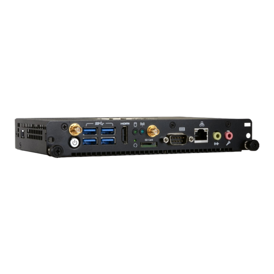
• One Quick Installation Guide • One DVD disk includes: - Manual Notes: 1. Throughout this guide the OPS100-SH may be referred to as the OPS+ Module. 2. The OPS-DB (referred to as the Docking Board) is an expansion dock, which provides additional I/O connectivity. - Page 2 Panel: OPS100-SH Antenna Hole HDD LED HDMI-in Antenna Hole USB 3.0 Wireless LED Front View Power Button Reset Button Line-out Mic-in microSD Card HRS FX18 JAE TX25A Rear View Panel: OPS-DB USB 3.0 USB 2.0 Power Button DP(B) DP(A) HDMI-out...
-
Page 3: Removing The Chassis Cover
Removing the Chassis Cover The OPS+ Module consists of a computing board in a wrapper chassis. Pease observe the following guidelines and follow the procedure to open the system. 1. Make sure the system and all other peripheral devices connected to it have been powered-off. - Page 4 Installing the OPS100-SH into a Display Integrating a computing system into a digital signage display is made easy by standardizing the connectors and signals between an OPS+ Module and an OPS-compliant display. Note that the OPS+ Module does not support hot swapping; do not power on the display before the installation is complete.
- Page 5 Installing the OPS100-SH into the OPS-DB The OPS+ Module has an accompanying Docking Board and allows it to serve as a standalone computing system. The plug and unplug mechanism between the OPS+ Module and the Docking Board utilizes the combo connector at the back of the module.
-
Page 6: Top View
Board Layout and Jumper Settings: OPS100-SH COM 1 Top View MicroSD Clear CMOS USB 3.0 USB 3.0 (J23) Power-on Battery (J3) Buzzer Intel Intel ® Xeon E3-1515M v5 Core™ i5-6440EQ Core™ i3-6100E CM236/HM170 SPI Flash BIOS JAE TX25A-80P HRS FX18-60S Bottom View M.2 Type 2280-S2-M... -
Page 7: Usb Power Select
Board Layout and Jumper Settings: OPS-DB HRS FX18-60P JAE TX24A-80R SYS Fan (J3) GPIO (J4) I2C (J6) PCIE1(PCIe 3.0 x4) Line_out (J5) USB PWR USB PWR (J16) (J15) AT/ATX mode +12V Slide Switch (J17) Power-on COM 1 USB Power Select J15 (for the USB 3.0 port) J16 (for the USB 2.0 ports) 1-2 On... -
Page 8: Connector Pin Assignment
USB: 1*USB 3.0 and 3*USB 2.0 Control and Sensors: 1*UART and Consumer Electronics Control (CEC, note that the OPS100-SH does not support this function) Control and Management Signals: the OPS+ Module power status, power- on via display panel, OPS+ Module detect, Consumer Electronics Control (CEC), system fan control, and device reset. - Page 9 TMDS0_2+ DVI-D USB_PP0 TMDS0_2- DVI-D USB_PN0 Ground Ground TMDS0_1+ DVI-D USB_PP1 TMDS0_1- DVI-D USB_PN1 Ground Ground TMDS0_0+ DVI-D USB_PP2 TMDS0_0- DVI-D USB_PN2 Ground Ground TMDS0_CLK+ DVI-D StdA_SSTX+ USB3.0 TMDS0_CLK- DVI-D StdA_SSTX- USB3.0 Ground DDP_HPD DisplayPort StdA_SSRX+ USB3.0 DDP_AUXP DisplayPort StdA_SSRX- USB3.0 DDP_AUXN DisplayPort...
- Page 10 The right angle mate plug connector (p/n: FX18-60S-0.8SH) should be mated with the receptacle connector (p/n: FX18-60P-0.8SH); together, they provide interfacing for the following functions: Power Contacts: 5V, 3V3@0.5A max Display Interface: 1*DisplayPort 1.2 (4K at 60Hz) PCI Express Expansion: 1*PCI-Express 3.0 x4 Control and Management Signals: 1*GPIO, 1*I2C, PHY device management signals The following table lists the pin assignments of the 60-pin HRS connector:...
- Page 11 The COM ports on the front panel of the OPS+ Module and the Docking Board provide serial communication. The following illustrations show the pin assignments of the COM port: COM 1 on OPS100-SH COM 1 on OPS-DB 1 2 3 4 5...
- Page 12 Both the OPS+ Module and the Docking Board provide pin headers for miscellaneous connectors. The following tables list the pin assignments of these connectors: CPU Fan (OPS100-SH: J1) LPC (OPS100-SH: J7) Pins Pin Assignment Pins Pin Assignment Pins Pin Assignment...
-
Page 13: Physical Dimension
Physical Dimension The overall dimensions of the OPS+ Module exclusive of the front panel frame is 180 x 30 x 119 mm (W x H x D). The following illustrations show the dimensions of the OPS+ Module as well as the dimension and location of the front panel screw holes: 200.00 180.00...
Need help?
Do you have a question about the OPS100-SH and is the answer not in the manual?
Questions and answers