
Related Manuals for DFI RM641-HD


Summary of Contents for DFI RM641-HD
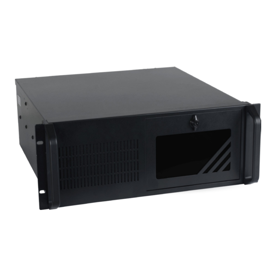
- Page 1 RM641-HD Desktop Box PC User’s Manual A44000637 Chapter 1 Introduction www.dfi.com...
-
Page 2: Copyright
Product names or trademarks appearing in this manual are for identification purpose only and Shielded interface cables must be used in order to comply with the emission limits. are the properties of the respective owners. Chapter 1 Introduction www.dfi.com... -
Page 3: Table Of Contents
Chassis Intrusion Connector ............. 29 Overview .................6 Front Panel Connector .............. 29 Specifications ................7 Standby Power LED ..............30 Getting to Know the RM641-HD ..........8 Expansion Slots ............... 30 Chapter 2 - Getting Started......10 S/PDIF Connector ..............31 Parallel Port ................31 LPC Debug Port ................ -
Page 4: About This Manual
After installation or servicing, cover the system chassis before plugging the power cord. Battery: • Danger of explosion if battery incorrectly replaced. • Replace only with the same or equivalent type recommend by the manufacturer. • Dispose of used batteries according to local ordinance. Chapter 1 Introduction www.dfi.com... -
Page 5: Safety Precautions
• Disconnect the system from the DC outlet before cleaning. Use a damp cloth. Do not use liquid or spray detergents for cleaning. Chapter 1 Introduction www.dfi.com... -
Page 6: Chapter 1 - Introduction
Chapter 1 Chapter 1 - Introduction Key Features Overview Model Name RM641-HD Processor 4th generation Intel ® Core processors Chipset Intel® H81 Chipset 2 LAN ports 2 COM ports Display 1 VGA, DVI-I (DVI-D signal) 4 USB 2.0 ports at the rear panel I/O ports;... -
Page 7: Specifications
Indicators 1 x Power LED 1 x HDD LED Front I/O 2 x USB 2.0 (available upon request) Front 1 x Drive Panel Door With Keylock Door Buttons 1 x Power Switch 1 x Reset Switch Chapter 1 Introduction www.dfi.com... -
Page 8: Getting To Know The Rm641-Hd
Chapter 1 Getting to Know the RM641-HD Front View Rear View Reset Power LED HDD LED Power DC-in Jack LAN 1-2 USB 3.0 Line-in USB 2.0 Line-out keyboard/mouse Mic-in DVI-I USB 2.0 Power Button DC-in jack Press to power on or power off the system. - Page 9 Mechanical Dimensions Chassis Dimensions Motherboard Dimensions Rear View 429.80 10.16 0.00 22.86 29.22 46.94 75.29 94.79 112.79 130.79 143.93 150.29 154.94 154.94 164.54 175.87 180.93 482.60 227.33 227.33 233.68 464.60 RESET POWER H.D.D. POWER Front View Chapter 1 Introduction www.dfi.com...
-
Page 10: Chapter 2 - Getting Started
Installing the Drivers The system package includes a CD disk. The CD includes drivers that must be installed to pro- vide the best system performance. Refer to the Supported Software chapter for instructions on installing the drivers. Chapter 2 Getting Started www.dfi.com... -
Page 11: Chapter 3 - Installing The Device
2. Align the mounting holes of the SATA drive with the mounting holes on the HDD brackets and 4. The DIMM sockets are readily accessible after removing the chassis cover. then use the mounting screws to secure the drive in place. DIMM socket Mounting screw DIMM socket SATA drive HDD bracket Chapter 3 Installing the Device www.dfi.com... - Page 12 The system can accommodate 4 disks (3.5” or 2.5”). However, 3.5” to 5.25” or 2.5” to 5.25” drive mounting bracket adapters will be required to install HDDs in the optical bays. SATA power and data connector Chapter 3 Installing the Device www.dfi.com...
-
Page 13: Installing The Dimm Module
2. Make sure to keep the protective cap. RMA requests will be accepted and pro- cessed only if the LGA 1150 socket comes with the protective cap. DIMM socket Protective cap Chapter 3 Installing the Device www.dfi.com... - Page 14 9. Hook the load lever under the retention tab. Important: The CPU will fit in only one orientation and can easily be inserted without exerting any force. Chapter 3 Installing the Device www.dfi.com...
-
Page 15: Installing The Fan And Heat Sink
“Locked” position of of push-pin push-pin Mounting hole Mounting hole 5. Connect the CPU fan’s cable to the CPU fan connector on the system board. CPU Fan connector Mounting hole Mounting hole Chapter 3 Installing the Device www.dfi.com... -
Page 16: Installing The Pci/Pcie Expansion Card
Disconnect all power cords and cables. Take off the card bracket secured on the system’s chassis. Install the PCIe expansion card on the system. Secure the PCIe expansion card to the system with the screws. Chapter 3 Installing the Device www.dfi.com... -
Page 17: Chapter 4 - Jumper Settings
2. Set JP9 pins 2 and 3 to On. Wait for a few seconds and set JP9 back to its default setting, pins 1 and 2 On. 3. Now plug the power cord and power-on the system. Chapter 4 Jumper Settings www.dfi.com... -
Page 18: Usb Power Select
If you are using the Wake-On-USB Keyboard/Mouse function for 2 USB ports, the +5V_standby power source of your power supply must support ≥1.5A. For 3 or more USB ports, the +5V_standby power source of your power supply must support ≥2A. Chapter 4 Jumper Settings www.dfi.com... -
Page 19: Com 1/Com 2 Rs232/422/485 Select
Serial COM port 2. The pin functions of Serial COM ports 1 and 2 to JP2. And when COM 2 RS232/422/485 is selected, JP19 and JP20 must be set in will vary according to these jumpers’ setting. accordante to JP16. Chapter 4 Jumper Settings www.dfi.com... -
Page 20: Com 1/Com 2 Rs232/Power Select
JP11 is used to select the power of SATA DOM. Note: SATA port 1 provides adequate space for SATA DOM. JP14 (for COM 1) and JP15 (for COM 2) are used to configure Serial COM ports to pure RS232 or RS232 with power. Chapter 4 Jumper Settings www.dfi.com... -
Page 21: Digital I/O Power Select
Based on the power level of DIO (Digital I/O) selected on JP13, JP12 (DIO pin 3/5/7/9) and JP7 (DIO pin 11/13/15/17) are used to select the state of DIO output: pull high or pull low. When selecting pull high, the power selection will be the same as JP13’s setting. Chapter 4 Jumper Settings www.dfi.com... -
Page 22: Chapter 5 - Ports And Connectors
Configure the wake-up function of PS/2 keyboard/mouse in the Advanced menu (“ACPI Power Management Configuration” submenu) of the BIOS. Refer to the chapter 7 for more informa- tion. Important: The +5V_standby power source of your power supply must support ≥720mA. Chapter 5 Ports and Connectors www.dfi.com... -
Page 23: Com (Serial) Ports
Select” and “COM 1/COM 2 RS232/Power Select“ in chapter 4 for more information. The serial ports are asynchronous communication ports with 16C550A-compatible UARTs that can be used with modems, serial printers, remote display terminals, and other serial devices. Chapter 5 Ports and Connectors www.dfi.com... -
Page 24: Graphics Interfaces
Install the LAN drivers. Refer to the chapter 8 for more information. BIOS Setting Configure the display devices in the Chipset menu (“System Agent Configuration” submenu) of the BIOS. Refer to the chapter 7 for more information. Chapter 5 Ports and Connectors www.dfi.com... -
Page 25: Usb Ports
2.0/1.1 ports (USB 2-3/10-11). The additional USB ports may be mounted on a card-edge bracket. Install the card-edge bracket to an available slot at the rear of the system chassis and then insert the USB port cables to a connector. Chapter 5 Ports and Connectors www.dfi.com... -
Page 26: Audio
The front audio connector allows you to connect to the second line-out and mic-in jacks that are at the front panel of your system. Driver Installation Install the audio driver. Refer to the chapter 8 for more information. Chapter 5 Ports and Connectors www.dfi.com... -
Page 27: Digital I/O Connector
The 8-bit Digital I/O connector provides powering-on function to external devices that are con- nected to these connectors. Digital I/O Connector Pins Pin Assignment Pins Pin Assignment +12V DIO7 +12V DIO6 DIO5 DIO4 DIO3 DIO2 +5V_Standby DIO1 +5V_Standby DIO0 Chapter 5 Ports and Connectors www.dfi.com... -
Page 28: Cooling Fan Connectors
Insufficient power supplied to the system may result in instability or the add-in boards and peripherals not functioning properly. Calculating the system’s approximate power usage is important to ensure that the power supply meets the system’s consumption requirements. Chapter 5 Ports and Connectors www.dfi.com... -
Page 29: Chassis Intrusion Connector
On Suspend) state, it will blink every second. When the system is in the S3 (STR - Suspend To RAM) state, it will blink every 4 seconds. Pin Pin Assignment Pin Pin Assignment HDD Power LED Power HDD-LED Signal PWR-LED LED Power Ground Signal RST Signal Ground RESET SW ATX-SW N.C. Signal Chapter 5 Ports and Connectors www.dfi.com... -
Page 30: Standby Power Led
Install PCI Express cards such as network cards or other cards that comply to the PCI Express specifications into the PCI Express x4 slot. ISA Slot The ISA slot is used to connect ISA-compatible expansion cards. Chapter 5 Ports and Connectors www.dfi.com... -
Page 31: S/Pdif Connector
Allows parallel port to operate in bidirectional mode and at a speed faster than the SPP’s data (Extended Capabilities Port) transfer rate. Allows bidirectional parallel port operation at maximum speed. (Enhanced Parallel Port) Chapter 5 Ports and Connectors www.dfi.com... -
Page 32: Lpc Debug Port
The LPC connector is used for the debug function and its pin functions are listed below. Pins Pin Assignment Pins Pin Assignment LAD1 RST# LAD0 FRAME# VCC_+3V LAD3 LAD2 SERIRQ 48MHz Chapter 5 Ports and Connectors www.dfi.com... -
Page 33: Lan Led Connector
• Replace only with the same or equivalent type recommend by the manufacturer. Pins Pin Assignment Pins Pin Assignment • Dispose of used batteries according to local ordinance Link Activity +3V_standby GLED_LED_1000- GLED_LED_100- Link Activity +3V_standby GLED_LED_1000- GLED_LED_100- Chapter 5 Ports and Connectors www.dfi.com... -
Page 34: Chapter 6 - Bios Setup
When ““ appears on the left of a particular field, it indicates that a submenu which contains restart the system by pressing the <Ctrl> <Alt> and <Del> keys simultaneously. additional options are available for that field. To display the submenu, move the highlight to that field and press <Enter>. Chapter 6 BIOS Setup www.dfi.com... -
Page 35: Ami Bios Setup Utility
The time format is <hour>, <minute>, <second>. The time is based on the 24-hour military-time clock. For example, 1 p.m. is 13:00:00. Hour displays hours from 00 to 23. Minute displays minutes from 00 to 59. Second displays seconds from 00 to 59. Chapter 6 BIOS Setup www.dfi.com... - Page 36 When Enabled, the system uses the RTC to generate a wakeup event. Wakeup Event After G3 This field is used to enable or disable the specific wakeup event after G3. It needs to switch the hardware jumper (for AC power on) to the proper setting. Chapter 6 BIOS Setup www.dfi.com...
- Page 37 Intel Virtualization Technology When this field is set to enabled, a VMM can utilize the additional hardware capabilities provided by Vanderpool Technology. EIST This field is used to enable or disable the Intel Enhanced SpeedStep Technology. Chapter 6 BIOS Setup www.dfi.com...
- Page 38 ↑↓: Software Preserve Unknown Enter: Select +/ -: Port 5 [Enabled] Change Opt. General Help Hot Plug [Disabled] Previous Values Optimized Defaults Save and Reset ESC: Exit Version 2.15.1236. Copyright (C) 2012 American Megatrends, Inc. Chapter 6 BIOS Setup www.dfi.com...
- Page 39 ESC: Exit EHCI Hand-off Version 2.15.1236. Copyright (C) 2012 American Megatrends, Inc. This is a workaround for OSes that does not support EHCI hand-off. The EHCI owner- ship change should be claimed by the EHCI driver. Chapter 6 BIOS Setup www.dfi.com...
- Page 40 ESC: Exit Selects the watchdog timer unit: second or minute. Version 2.15.1236. Copyright (C) 2012 American Megatrends, Inc. Super IO Watchdog Timer Sets the timeout value of the super IO watchdog timer. 0 means disabled. Chapter 6 BIOS Setup www.dfi.com...
- Page 41 Version 2.15.1236. Copyright (C) 2012 American Megatrends, Inc. Version 2.15.1236. Copyright (C) 2012 American Megatrends, Inc. Serial Port Enables or disables these serial ports (COM). Change Settings Selects the IO/IRQ settings for the super I/O device. Chapter 6 BIOS Setup www.dfi.com...
- Page 42 Boundary 1 General Help Speed Count 5 Previous Values Speed Count 4 Optimized Defaults Speed Count 3 Save & Reset Speed Count 2 ESC: Exit Speed Count 1 Version 2.15.1236. Copyright (C) 2012 American Megatrends, Inc. Chapter 6 BIOS Setup www.dfi.com...
- Page 43 Change Settings [Auto] Select Screen → ←: Select Item ↑↓: Enter: Select +/ -: Change Opt. General Help Previous Values Optimized Defaults Save and Reset ESC: Exit Version 2.15.1236. Copyright (C) 2012 American Megatrends, Inc. Chapter 6 BIOS Setup www.dfi.com...
- Page 44 Change Settings [Auto] Select Screen → ←: Select Item ↑↓: Enter: Select +/ -: Change Opt. General Help Previous Values Optimized Defaults Save and Reset ESC: Exit Version 2.15.1236. Copyright (C) 2012 American Megatrends, Inc. Chapter 6 BIOS Setup www.dfi.com...
- Page 45 Ipv6 PXE Support [Enabled] Select Screen → ←: Select Item ↑↓: Enter: Select +/ -: Change Opt. General Help Previous Values Optimized Defaults Save and Reset ESC: Exit Version 2.15.1236. Copyright (C) 2012 American Megatrends, Inc. Chapter 6 BIOS Setup www.dfi.com...
- Page 46 Blink LEDs Enables this option to wake the system with a magic packet. Blink LEDs for the specified duration (up to 15 seconds). Link Status This field indicates the link status of the network device. Chapter 6 BIOS Setup www.dfi.com...
- Page 47 Link Status Wake on LAN This field indicates the link status of the network device. Enables this option to wake the system with a magic packet. Alternate MAC Address Alternates assigned MAC address of Ethernet port. Chapter 6 BIOS Setup www.dfi.com...
- Page 48 Save and Reset Optimized Defaults ESC: Exit Save and Reset ESC: Exit Version 2.15.1236. Copyright (C) 2012 American Megatrends, Inc. Version 2.15.1236. Copyright (C) 2012 American Megatrends, Inc. VT-d Enables the VT-d function on MCH. Chapter 6 BIOS Setup www.dfi.com...
- Page 49 DVMT Total Gfx Mem 128M Select Screen → ←: Select Item ↑↓: 256M Enter: Select +/ -: Change Opt. General Help Previous Values Optimized Defaults Save & Reset ESC: Exit Version 2.15.1236. Copyright (C) 2012 American Megatrends, Inc. Chapter 6 BIOS Setup www.dfi.com...
- Page 50 ↑↓: Enter: Select +/ -: Change Opt. General Help Previous Values Optimized Defaults Save & Reset ESC: Exit Version 2.15.1236. Copyright (C) 2012 American Megatrends, Inc. Secondary IGFX Boot Display Selects the secondary display device. Chapter 6 BIOS Setup www.dfi.com...
- Page 51 Onboard I217 LAN Controller Enables or disables the onboard I217 LAN controller. Onboard 82574 LAN Controller Enables or disables the onboard 82574 LAN controller High Precision Timer Enables or disables the High Precision Event Timer. Chapter 6 BIOS Setup www.dfi.com...
- Page 52 Change Opt. General Help Previous Values Optimized Defaults Save & Reset ESC: Exit Version 2.15.1236. Copyright (C) 2012 American Megatrends, Inc. PCIe Speed Selects the speed of PCI Express port: Auto, Gen 1 or Gen 2. Chapter 6 BIOS Setup www.dfi.com...
- Page 53 EHCI 1 and EHCI 2 Precondition works on USB host controller and root ports for faster enumeration. These fields are used to control the functions of USB EHCI (USB 2.0) controllers One EHCI controller must always be enabled. Chapter 6 BIOS Setup www.dfi.com...
- Page 54 Save & Reset Optimized Defaults ESC: Exit Save & Reset ESC: Exit Version 2.15.1236. Copyright (C) 2012 American Megatrends, Inc. Version 2.15.1236. Copyright (C) 2012 American Megatrends, Inc. USB Port #0/1/2/3/4/5/8/9/10/11 Enables or disables these USB ports. Chapter 6 BIOS Setup www.dfi.com...
- Page 55 Controls the execution of UEFI and legacy storage OpROM. Other PCI device ROM priority Quiet Boot For PCI devices other than Network, Mass Storage, or Video defines which Enables or disables the quiet boot function. OpROM to launch. Chapter 6 BIOS Setup www.dfi.com...
- Page 56 <Enter>. A dialog box will appear. Select Yes to restore the default values of all the setup options. Launch EFI Shell from filesystem device Attempts to Launch EFI Shell application (Shellx64.efi) from one of the available filesystem devices. Chapter 6 BIOS Setup www.dfi.com...
-
Page 57: Updating The Bios
EEPROM programmer has been burned and follow the Verifying flash ......done technical person's instructions to confirm that the MAC address should be burned Erasing BootBlock ....done Writing BootBlock ....done or not. Verifying BootBlock ....done C:\AFU\AFUDOS> Chapter 6 BIOS Setup www.dfi.com... -
Page 58: Chapter 7 - Supported Software
CD screen did not appear), please go directly to the root directory of the CD and double-click “Setup”. 1. Setup is ready to install the utility. Click Next. For Windows Embedded Standard 7 2. Read the license agreement then click Yes. www.dfi.com Chapter 7 Supported Software... - Page 59 Chapter 7 3. Go through the readme document for more installa- tion tips then click Next. 4. Click Finish to exit setup. www.dfi.com Chapter 7 Supported Software...
- Page 60 To install the driver, click “Intel Management Engine Drivers” on the main menu. 1. Setup is ready to install the driver. Click Next. 4. After completing installa- tion, click Finish. 2. Read the license agreement then click Yes. www.dfi.com Chapter 7 Supported Software...
- Page 61 1. Setup is ready to install the driver. Click Next. 2. Click “Yes, I want to restart my computer now” then click Finish. Restarting the system will allow the new software installation to take effect. www.dfi.com Chapter 7 Supported Software...
- Page 62 DFI Utility 3. Click “Install” to begin the installation. DFI Utility provides information about the board, Watchdog,and DIO. To access the utility, click “DFI Utility” on the main menu. Note: If you are using Windows 7, you need to access the operating system as an administrator to be able to install the utility.
- Page 63 Chapter 7 The DFI Utility icon will appear on the desktop. Double-click the icon to open the utility. HW Health Set Information WatchDog HW Health www.dfi.com Chapter 7 Supported Software...
- Page 64 1. The setup program is preparing to install the driver. 2. The setup program is now ready to install the utility. Click Next. 3. Click “I accept the terms in the license agreement” and then click “Next”. www.dfi.com Chapter 7 Supported Software...
- Page 65 Visual C++ package prior to installing the utility. Click Install. 5. Select a setup type and then click 8. The setup program is currently Next. installing the Microsoft Visual C++ package. 9. Click Finish. 6. Click Install. www.dfi.com Chapter 7 Supported Software...
- Page 66 To install the reader, click “Adobe Acrobat Reader 9.3” on the main menu. 1. Click Next to install or click Change Destination Folder to select another folder. 2. Click Install to begin installa- tion. 3. Click Finish to exit installation. www.dfi.com Chapter 7 Supported Software...
-
Page 67: Appendix A - System Error Message
The BIOS reports memory test fail if the memory has error(s). VIDEO selection. FLOPPY DISK(S) fail (80) Unable to reset floppy subsystem. FLOPPY DISK(S) fail (40) Floppy type mismatch. Hard Disk(s) fail (80) HDD reset failed. Hard Disk(s) fail (40) HDD controller diagnostics failed. Appendix A System Error Message www.dfi.com... -
Page 68: Appendix B - Troubleshooting Checklist
4. There is not enough space left on the diskette. Use another diskette with adequate storage 4. Adjust the brightness of the display by turning the monitor’s brightness control knob. space. Appendix B Troubleshooting Checklist www.dfi.com... -
Page 69: Hard Drive
Nothing happens when a key on the keyboard was pressed. 1. Make sure the keyboard is properly connected. 2. Make sure there are no objects resting on the keyboard and that no keys are pressed dur- ing the booting process. Appendix B Troubleshooting Checklist www.dfi.com...
Need help?
Do you have a question about the RM641-HD and is the answer not in the manual?
Questions and answers