
Subscribe to Our Youtube Channel
Related Manuals for DFI OPS150-CS


Summary of Contents for DFI OPS150-CS
- Page 1 OPS150-CS Digital Signage Embedded OPS Computer User’s Manual Preliminary Preliminary Version Version A-584-M-2016...
- Page 2 1. The changes or modifications not expressly approved by the party responsible for com- pliance could void the user’s authority to operate the equipment. 2. Shielded interface cables must be used in order to comply with the emission limits. User's Manual | OPS150-CS...
-
Page 3: Table Of Contents
Installing the Wifi Antenna for the M.2 E Key Wifi Module (Optional) ......27 OPS Display ........................28 Chapter 3 - BIOS Settings ......................29 Overview ..........................29 Main ............................30 Advanced ..........................30 RC ACPI Configuration ....................31 CPU Configuration ......................31 Power & Performance ....................32 PCH-FW Configuration ....................32 Trusted Computing ......................33 User's Manual | OPS150-CS... - Page 4 The system and accessories in the package may not come similar to the information listed above. This may differ in accordance with the sales region or models in which it was sold. For more information about the standard package in your region, please contact your dealer or sales representative. User's Manual | OPS150-CS...
- Page 5 Make sure the system is placed or mounted correctly and stably to prevent the chance of dropping or falling may cause damage. • The openings on the system shall not be blocked and shall be kept in distance from User's Manual | OPS150-CS...
-
Page 6: Chapter 1 - Introduction
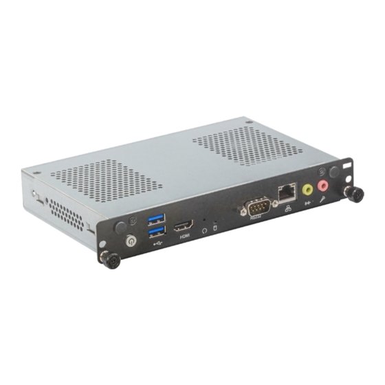
The specifications listed here may be based on editions that do not Display 1 x HDMI 1.4 output resemble your actual products. Please visit the download page at go.dfi. com/OPS150-CS, or via the QR code to the right for the latest datasheet. Audio 1 x Line-out 1 x Mic-in Buttons... -
Page 7: Features
Event) signal. However, if your system is in the Suspend mode, you can power-on the system only through an IRQ or DMA interrupt. Wake-On-USB This function allows you to use a USB keyboard or USB mouse to wake up a system from the S3 (STR - Suspend To RAM) state. User's Manual | OPS150-CS... -
Page 8: Chapter 2 - Hardware Installation
USB 3.0 Reset RS232 Mic In Bracket Bracket Atenna Atenna Hole Hole Mounting Mounting Screw Screw Dimensions Power Button HDMI SSD LED Audio Out Rear Panel I/O 180.00 30.00 JAE TX25 Top and Side View 200.00 User's Manual | OPS150-CS... -
Page 9: Installation
When removing the OPS module, completely cut off the power of both the OPS mounting if the OPS display has tapped screw holes for them. module and the OPS display, and remove the power cable to rule out any chances of ESD/EOS damage to the system. User's Manual | OPS150-CS... -
Page 10: Assembly
Use a Phillips screwdriver to unscrew them. After the six above-mentioned screws are removed, place the system on a stable work surface, and slide the cover towards the rear before removing it. Front Panel Bottom User's Manual | OPS150-CS... -
Page 11: Heatsink And Fan
When installed correctly, the locations of the bracket and the screws shall resemble the follow- heatsink on the right ing photos. Screws Installation Steps Overview Step 1: Fan Bracket Installation Step 2: Heatsink Installation Step 3: PCH Heat Spreader Installation Step 4: Fan Installation User's Manual | OPS150-CS... - Page 12 Since the springs of the screws are highly resilient and lopsidedness of the screwed-on heatsink may cause uneven pressure and possible damage to the CPU and board, it is highly suggested that, during the installation/disassembly, the heat- sink is applied additional pressure to remain parallel to the board. User's Manual | OPS150-CS...
- Page 13 Fan Screw A on top of the Fan Screw A Stand-off, and Fan Screw B on one of the screw holes on the fan bracket. Fan Screw A Config 2: Fan on the left and heatsink on the right Fan Screw B Fan Connector Fan Screw B User's Manual | OPS150-CS...
- Page 14 Install/remove the fan by screwing/unscrewing the two M2*4 round- head screws at two locations — Fan Screw A and Fan Screw B — with regard to the two heatsink and fan configurations. User's Manual | OPS150-CS...
-
Page 15: Module Bracket
Place the system on a stable work surface stand-offs with its bottom side facing up. Unscrew the zinc-coated screw. PART NO: A31-022157-500G Lift up the bracket at the side closer to the screw hole and remove it to reveal the socket. User's Manual | OPS150-CS 6.71 6.67... -
Page 16: Board Layout
If a wrist strap is unavailable, establish and maintain contact with the system chassis throughout any procedures requiring ESD protection. User's Manual | OPS150-CS... -
Page 17: System Memory
DIMMs. Not all slots need to be populated. Dual Channel DIMMs of the same memory configuration are on different channels. Notch DDR4 SO-DIMM Features Retention Clip • Two 260-pin SO-DIMM up to 32GB • Dual Channel DDR4 2666MHz Socket Top View User's Manual | OPS150-CS... - Page 18 Inspect that the clip sits in the notch. If not, please pull the clips outward, release and remove the Step 3 card, and mount it again. User's Manual | OPS150-CS...
-
Page 19: Cpu
These illustrations and photos are for reference only. 4. Unlock the socket by pressing the load lever down, moving it sideways until to escape the retention tab. Lift the load lever up when it’s released. Load lever Retention tab User's Manual | OPS150-CS... - Page 20 Important: 9. Press down the load The CPU will fit in only one orientation and can easily be seated without exerting lever and hook it under any force. the retention tab. User's Manual | OPS150-CS...
-
Page 21: Jumper Settings
1 and pin 2. 3. Plug the power cord and power-on the system. M Key m Side) JAE TX25 „ 1-2 On: Normal (default) „ 2-3 On: Clear CMOS M.2 E Key SPI Flash BIOS User's Manual | OPS150-CS... -
Page 22: I/O Ports
A ports at the front panel — two USB 3.1 Gen1 ports. Wake-On-USB Keyboard/Mouse The Wake-On-USB Keyboard/Mouse function allows you to use a USB keyboard or USB mouse to wake up a system from the S3 (STR - Suspend To RAM) state. User's Manual | OPS150-CS... -
Page 23: Rj45 Lan Ports
The LAN port allows the system board to connect to a local area network by means of a net- can be used with modems, serial printers, remote display terminals, and other serial devices. work hub. Features • Realtek RTL8111H GbE Lan controller User's Manual | OPS150-CS... -
Page 24: Audio
L_RST# L_LAD0 L_FRAME# 3.3V • Line-out Jack (Lime) L_LAD3 This jack is used to connect a headphone or external speakers. L_LAD2 • Mic-in Jack (Pink) SERIRQ This jack is used to connect an external microphone. 5VSB User's Manual | OPS150-CS... -
Page 25: Battery
CPU FAN Out • Dispose of used batteries according to local ordinances. M Key m Side) JAE TX25 M.2 M Key SPI Flash BIOS M.2 E Key (Bottom Side) JAE TX25 SPI Flash BIOS M.2 E Key User's Manual | OPS150-CS... -
Page 26: Expansion Slots
The M.2 E Key socket can only be accessed after the top cover, the heatsink or the fan are removed. The M.2 M key can be accessed by opening the module bracket on the bottom of the chassis as previously instructed in this chapter. User's Manual | OPS150-CS... -
Page 27: Installing The Wifi Antenna For The M.2 E Key Wifi Module (Optional)
Module Connector Cable Antenna Connector Washer and a stand-off screw until the gap between the card and the stand-off closes up. The card should be lying parallel to the board when it’s correctly mounted. User's Manual | OPS150-CS... -
Page 28: Ops Display
The JAE TX25 connector is used for mounting the OPS module onto an OPS display. HPD_HMTX 19VSB/12VSB PWR_BTN- 19VSB/12VSB SYSPWROK_OPS_B2B Function Function 19VSB/12VSB DDI1_TX3_DN N.C. 19VSB/12VSB DDI1_TX3_DP N.C. 19VSB/12VSB N.C. 19VSB/12VSB DDI1_TX2_DN N.C. 19VSB/12VSB DDI1_TX2_DP N.C. 19VSB/12VSB User's Manual | OPS150-CS... -
Page 29: Chapter 3 - Bios Settings
When “X” appears on the left of a particular field, it indicates that a submenu which contains additional options are available for that field. To display the submenu, move the highlight to that field and press <Enter>. User's Manual | OPS150-CS... -
Page 30: Main
The time format is <hour>, <minute>, <second>. The time is based on the 24-hour military-time clock. For example, 1 p.m. is 13:00:00. Hour displays hours from 00 to 23. Minute displays min- utes from 00 to 59. Second displays seconds from 00 to 59. User's Manual | OPS150-CS... -
Page 31: Rc Acpi Configuration
Last State The system automatically the last state right before the power failure. Note: Some of the fields may not be available when the features are not supported by the equipped CPU. User's Manual | OPS150-CS... -
Page 32: Power & Performance
Version 2.20.1275. Copyright (C) 2020 American Megatrends, Inc. the equipped CPU. Me FW Image Re-Flash This field is used to enable or disable the ME FW Image Re-Flash function, which allows the user to update the ME firmware. User's Manual | OPS150-CS... -
Page 33: Nct5525D Super Io Configuration
Set SuperIO WatchDog Timer Timeout value. The range is from 0 (disabled) to 255. To clear the existing TPM encryption, select "TPM Clear" and restart the system. This field is not available when "Security Device Support" is disabled. Note: The sub-menu is detailed in following sections. User's Manual | OPS150-CS... -
Page 34: Nct5525D Hw Monitor
Serial Port This section displays the system’s health information, i.e. voltage readings, CPU and system temperatures, and fan speed readings. Enable or disable the current serial COM port. Note: The actual number of serial ports may differ. User's Manual | OPS150-CS... -
Page 35: Serial Port Console Redirection
Manual PWM Setting The actual number of serial ports may differ. Set the fan speed, the value ranging from 1-100%, 100% being full speed. The fans will al- ways operate at the specified speed regardless of gauged temperatures. User's Manual | OPS150-CS... -
Page 36: Usb Configuration
Enable or disable USB Mass Storage Driver Support. Parity Select parity bits: None, Even, Odd, Mark or Space. Stop Bits Select stop bits: 1 bit or 2 bits. Flow Control Select flow control type: None or Hardware RTS/CTS. User's Manual | OPS150-CS... -
Page 37: Csm Configuration
This field controls the execution of UEFI and Legacy Storage OpROM. Video This field controls the execution of UEFI and Legacy Video OpROM. Other PCI devices This field determines OpROM execution policy for devices other than Network, Storage or Video. User's Manual | OPS150-CS... -
Page 38: Network Stack Configuration
Set the wait time in seconds to press ESC key to abort the PXE boot. Use either +/- or numeric keys to set the value. Media detect count Set the number of times the presence of media will be checked. Use either +/- or numeric keys to set the value. User's Manual | OPS150-CS... -
Page 39: Chipset
Version 2.20.1275. Copyright (C) 2020 American Megatrends, Inc. Version 2.20.1275. Copyright (C) 2020 American Megatrends, Inc. Primary Display Select which of IGFX/PEG/PCI Graphics device to be the primary display. Internal Graphics Keep IGFX enabled based on the setup options. User's Manual | OPS150-CS... -
Page 40: Pch-Io Configuration
"Dynamic" so that the assignment would adjust TOLUD automatically based on largest MMIO length of installed graphic controller. the PCIE1 port. This field may not appear when the speed of the port is not configurable. Note: The sub-menus are detailed in following sections. User's Manual | OPS150-CS... -
Page 41: Sata And Rst Configuration
SATA Mode Selection The mode selection determines how the SATA controller(s) operates. AHCI This option allows the Serial ATA controller(s) to use AHCI (Advanced Host Control- ler Interface). Port 2 Enable or disable the Serial ATA port. User's Manual | OPS150-CS... -
Page 42: Security
Secure Boot. Press Enter and a prompt will show up for you to confirm. Reset To Setup Mode Clear the database from the NVRAM, including all the keys and signatures installed in the Key Management menu. Press Enter and a prompt will show up for you to confirm. User's Manual | OPS150-CS... -
Page 43: Boot
This field will appear only when a USB flash device is detected. Select this field to restore set- only” and “Quiet Boot” is set to enabled, “BGRT Logo” will show up for configura- ting from the USB flash device. tion. Refer to the Advanced > CSM Configuration for more information. User's Manual | OPS150-CS... -
Page 44: Updating The Bios
When the BIOS IC needs to be replaced, you have to populate it properly onto the system board after the EEPROM programmer has been burned and follow the technical person's instructions to confirm that the MAC address should be burned or not. User's Manual | OPS150-CS... -
Page 45: Chapter 4 - Supported Software
Click “More >>” on the lower right to go to the next page of the auto-run menu, and click “<< Previous” to return to the previous menu. Note: This step can be ignored if the applications are downloaded standalone files. User's Manual | OPS150-CS... -
Page 46: Intel Hd Graphics Drivers
We recommend that you skip this process by disabling this function then click “Next”. 2. Read the license agreement then click “Yes”. 5. After completing installation, click “Restart Now” to exit setup. Restarting the system will al- low the new software installa- tion to take effect. User's Manual | OPS150-CS... -
Page 47: Realtek Audio Drivers
5. Click “Yes, I want to restart this computer now” then click “Fin- ish”. Restarting the system will al- low the new software installa- tion to take effect. User's Manual | OPS150-CS... -
Page 48: Intel Me Drivers
4. Please wait while the product 2. Read the license agreement is being installed. then tick “I accept the terms in the License Agreement”. Click “Next”. 5. After completing installation, click “Finish”. User's Manual | OPS150-CS... -
Page 49: Intel Serial Io Drivers
Click “Next”. and installation tips then click “Next”. 2. Read the license agreement carefully. Tick “I accept the terms in the 4. Setup is ready to install the License Agreement” then click driver. Click “Next”. “Next”. User's Manual | OPS150-CS... -
Page 50: Intel Rapid Storage Technology
“Fin- ish”. Restarting the system will al- 2. Read the license agreement low the new software installa- and click “I accept the terms in tion to take effect. the License Agreement”. Then, click “Next”. User's Manual | OPS150-CS... - Page 51 “Fin- tion then click “Next”. ish”. 4. Click “Next” to install to the default folder or click “Change to choose another destination folder”. 5. Confirm the installation and click “Next”. User's Manual | OPS150-CS...
-
Page 52: Intel Wi-Fi Drivers
3. Wait for the installer to finish the WiFi driver. Click “Next” to installation. start. 2. Reader the agreement thor- 4. Click "Finish" to complete. oughly, check the "I agree box", and click "Next" to proceed. User's Manual | OPS150-CS... -
Page 53: Intel Bluetooth Drivers
1. The installer is ready to install the driver. Click “Next” to start. 4. Select a setup suit and click "Next" to proceed. 2. Click "Next" to proceed. 5. Click "Install" to start the instal- lation. User's Manual | OPS150-CS... -
Page 54: Realtek Lan Driver
1. Setup is ready to install the driver. Click “Next”. 6. Wait for the installer to finish installation. 2. Click “Install” to begin the installation. 7. Click "Finish" to complete. 3. The step displays the installing status in the progress. User's Manual | OPS150-CS... -
Page 55: Adobe Acrobat Reader 9.3
X Adobe Acrobat Reader 9.3 1. Click “Next” to install or click 3. Setup is now installing the driver. “Change Destination Folder” to select another folder. 2. Click “Install” to begin installa- 4. Click “Finish” to exit installa- tion. tion. User's Manual | OPS150-CS...
Need help?
Do you have a question about the OPS150-CS and is the answer not in the manual?
Questions and answers