GE 750 Instruction Manual
Feeder management relay
Hide thumbs
Also See for 750:
- Instruction manual (504 pages) ,
- Manual (102 pages) ,
- Quick reference manual (58 pages)
Table of Contents
Advertisement
Quick Links
Title Page
g
GE Multilin
215 Anderson Avenue, Markham, Ontario
Canada L6E 1B3
Tel: (905) 294-6222
Fax: (905) 201-2098
Internet:
http://www.GEmultilin.com
750/760
Feeder Management Relay
INSTRUCTION MANUAL
Software Revision: 7.0x
Manual P/N: 1601-0120-A5
Manual Order Code: GEK-106471D
Copyright © 2005 GE Multilin
GE Industrial Systems
ISO9001:2000
GE Multilin's Quality
Management System is
registered to ISO9001:2000
QMI # 005094
UL # A3775
Advertisement
Table of Contents

Related Manuals for GE 750


Summary of Contents for GE 750
- Page 1 GE Industrial Systems 750/760 Feeder Management Relay INSTRUCTION MANUAL Software Revision: 7.0x Manual P/N: 1601-0120-A5 Manual Order Code: GEK-106471D Copyright © 2005 GE Multilin ISO9001:2000 GE Multilin 215 Anderson Avenue, Markham, Ontario Canada L6E 1B3 Tel: (905) 294-6222 Fax: (905) 201-2098...
-
Page 3: Table Of Contents
Table of Contents 750/760 Table of Contents Feeder Management Relay GETTING STARTED Important Procedures Cautions and Warnings ........................1-1 Inspection Checklist ..........................1-1 Manual Organization .......................... 1-2 Using the Relay Menu Navigation ..........................1-2 Panel Keying Example........................1-5 Changing Setpoints Introduction ............................ - Page 4 Flash Messages ...........................4-8 EnerVista 750/760 setup Software Interface Overview ............................4-10 Hardware............................4-10 Installing the EnerVista 750/760 setup Software................4-12 Connecting EnerVista 750/760 setup to the Relay Configuring Serial Communications....................4-14 Using the Quick Connect Feature.....................4-15 Configuring Ethernet Communications ...................4-16 Connecting to the Relay ........................4-17 Working with Setpoints and Setpoint Files Engaging a Device ..........................4-18...
- Page 5 750/760 Table of Contents Feeder Management Relay SETPOINTS Overview Setpoints Main Menu ......................... 5-1 Setpoint Entry Methods ........................5-4 Setpoint Access Security........................5-5 Common Setpoints..........................5-5 Logic Diagrams ........................... 5-6 S1 Relay Setup Passcode.............................. 5-7 Communications..........................5-8 Clock..............................5-10 Event Recorder..........................5-11 Trace Memory ...........................
- Page 6 750/760 Table of Contents Feeder Management Relay Equipment ............................5-90 Pulse Output ............................5-96 S7 Control Setpoint Groups ..........................5-97 Synchrocheck...........................5-100 Manual Close Blocking........................5-102 Cold Load Pickup ..........................5-104 Undervoltage Restoration.......................5-106 Underfrequency Restore .........................5-107 Transfer Scheme ..........................5-108 Autoreclose (760 only) ........................5-122 S8 Testing Output Relays ..........................5-133 Pickup Test ............................5-134...
- Page 7 On-Load Testing..........................7-64 Dielectric Strength Testing....................... 7-65 APPENDIX Relay Mods Reverse Power ............................ 8-1 Conformity EU Declaration of Conformity......................8-3 Revision History Release Dates ............................8-4 Release Notes............................8-4 GE Multilin Device Warranty Warranty Statement ........................... 8-5 GE Multilin http://www.GEmultilin.com...
-
Page 8: Table Of Contents
750/760 Table of Contents Feeder Management Relay INDEX GE Multilin viii http://www.GEmultilin.com... -
Page 9: Getting Started
GE Multilin website at http://www.GEmultilin.com. If there is any noticeable physical damage, or any of the contents listed are missing, please contact GE Multilin immediately. NOTE GE Multilin contact information and call center for product support: GE Multilin 215 Anderson Avenue Markham, Ontario... -
Page 10: Manual Organization
Specifications on page 2–7. The remainder of this manual should be read and kept for reference to ensure maximum benefit from the 750 and 760. For further information, please consult your local sales representative or the factory. Comments about new features or modifications for your specific requirements are welcome and encouraged. - Page 11 750/760 Using the Relay Feeder Management Relay SETPOINTS ACTUAL VALUES TARGET MESSAGES [ ] Press the MENU key to display the header for the setpoints menu, then press the MESSAGE key to display the header of the first setpoints page. The setpoint pages are numbered, have an ‘S’...
- Page 12 750/760 Using the Relay Feeder Management Relay If instead you press the MESSAGE key, the display will return to the previous sub-page heading; in this case, ENERGY When the symbols appear on the top line, it indicates that additional sub-pages are available and can be accessed by pressing the MESSAGE key.
-
Page 13: Panel Keying Example
A complete editable setpoint chart is available as an Excel spreadsheet from the GE Multilin website at http://www.GEmultilin.com. All of the 750/760 settings fall into one of following categories: device settings, system settings, logic input settings, output relay settings, monitoring settings, control settings, and testing settings. -
Page 14: The Help Key
Two methods of editing and storing a numerical setpoint value are available. The first method uses the 750/760 numeric keypad in the same way as any electronic calculator. A number is entered one digit at a time with the 0 to 9 and decimal keys. -
Page 15: Enumeration Setpoints
750/760 Changing Setpoints Feeder Management Relay message will momentarily appear as confirmation of the storing process. If 69.28 were entered, it would be automatically rounded to 69.3. NEW SETPOINT STORED Enumeration Setpoints Enumeration setpoints have data values which are part of a set whose members are explicitly defined by a name. - Page 16 750/760 Changing Setpoints Feeder Management Relay Press the MENU key until the relay displays the setpoints menu header. SETPOINTS MESSAGE Press SETPOINTS S1 RELAY SETUP MESSAGE Press Press Press SETPOINTS CURRENT PHASE CT PRIMARY: MESSAGE MESSAGE S2 SYSTEM SETUP SENSING...
- Page 17 750/760 Changing Setpoints Feeder Management Relay Press the MENU key until the relay displays the setpoints menu header. MENU Press SETPOINTS MESSAGE Press SETPOINTS S1 RELAY SETUP Press MESSAGE Press SETPOINTS CURRENT MESSAGE S2 SYSTEM SETUP SENSING Press Press BUS VT SENSING...
-
Page 18: Output Relay Setpoints
750/760 Changing Setpoints Feeder Management Relay To have access to information on maximum, minimum, step value, and information on technical support, press the HELP key. For the previous example, pressing the HELP key during setpoint entry displays the corresponding minimum, maximum and step values for the displayed setpoint, as well as contact information if further assistance is required. -
Page 19: Text Setpoints
– any additional intentional time delay – directionality (if applicable) • Define how many output contacts will be energized in response to a given pro- tection function. Note that the 750/760 relay can be programmed to trip and, at GE Multilin 1–11 http://www.GEmultilin.com... - Page 20 Define if the output relays will be set as fail-safe type. • Define if the 750/760 will be used to close the breaker. If that will be the case, gather information on the conditions that will be used to verify synchronism.
- Page 21 750/760 Application Example Feeder Management Relay FIGURE 1–1: Typical Three-Line Diagram GE Multilin 1–13 http://www.GEmultilin.com...
- Page 22 750/760 Application Example Feeder Management Relay RS485 SERIAL NETWORK FIGURE 1–2: Typical Connection Diagram GE Multilin 1–14 http://www.GEmultilin.com...
- Page 23 750/760 Application Example Feeder Management Relay FIGURE 1–3: Typical Control Diagram GE Multilin 1–15 http://www.GEmultilin.com...
- Page 24 750/760 Application Example Feeder Management Relay FIGURE 1–4: Typical Breaker Control Diagram GE Multilin 1–16 http://www.GEmultilin.com...
- Page 25 750/760 Application Example Feeder Management Relay FIGURE 1–5: Typical Relay Control Diagram GE Multilin 1–17 http://www.GEmultilin.com...
- Page 26 RTU. Please note that, similar information could be exchanged between the RTU and the relay via an RS485 or RS422 serial link using Modbus RTU protocol. Refer to GE Publication GEK-106473: 750/760 Communications Guide for additional information. •...
-
Page 27: S2 System Setpoints
For additional information, refer to Bus VT Sensing on page 5–17. The 750/760 was designed to display primary system values. Current and voltage measurements are performed at secondary levels, which the relay transforms to primary values using CT and VT ratios, as well as nominal secondary values. -
Page 28: S3 Logic Inputs Setpoints
750/760 Application Example Feeder Management Relay S3 Logic Inputs The S3 setpoints page is for entering the characteristics of the logic inputs. In our Setpoints example, these characteristics are specified under the Control System Requirements heading. Program the S3 setpoints as indicated. -
Page 29: S5 Protection Setpoints
750/760 Application Example Feeder Management Relay “Input 3” LOCAL MODE: “Input 6” RESET: “Input 4” REMOTE OPEN: “Input 5” REMOTE CLOSE: If, for example, the same logic input would be needed to perform the functionality of Close and Reset, then the following should have been entered: “Input 5”... -
Page 30: Installation
A minor self-test warning message informs the user that the 750/760 has not yet been programmed. If this warning is ignored, protection is active and will be using factory default setpoints. The Relay In Service LED Indicator will be on. -
Page 31: Introduction
To simplify programming and provide a more intuitive interface, setpoints can be entered with a PC running the EnerVista 750/760 Setup software provided with the relay. Even with minimal computer knowledge, this menu-driven software provides easy access to all front panel functions. - Page 32 750/760 Overview Feeder Management Relay ANSI PROTECTION / CONTROL Bus / Line Undervoltage Negative Sequence Voltage Phase/Neutral/Gnd/Neg Seq/Sens Gnd Inst O/C Phase/Neutral/Gnd/Neg Seq/Sens Gnd Time O/C Bus Overvoltage/Neutral Displacement Phase/Neutral/Neg Seq/Sens Gnd/Gnd Directional Control Bus Underfrequency/Rate of Change Undervoltage Automatic Restoration Underfrequency Automatic Restoration Breaker Failure with Current Superv.
-
Page 33: Theory Of Operation
These ‘raw’ samples are calibrated in software and then placed into the waveform capture buffer thus emulating a fault recorder. The waveforms can be retrieved from the relay via the EnerVista 750/760 Setup software for display and diagnostics. -
Page 34: Frequency Tracking
FFT algorithm for off- nominal frequencies. Also, sampling is synchronized to the Va-x voltage zero crossing which results in better co-ordination for multiple 750/760 relays on the same bus. If a stable frequency signal is not available then the sampling rate defaults to the nominal system frequency. - Page 35 750/760 Theory of Operation Feeder Management Relay FIGURE 2–3: Hardware Block Diagram GE Multilin 2–5 http://www.GEmultilin.com...
-
Page 36: Ordering
TABLE 2–1: 750/760 Order Codes 750 Feeder Management Relay 750 – * – * – * – * – * – * – * – * 760 Feeder Management Relay 760 – * – * – * – * – * – * – * – *... -
Page 37: Specifications
Specifications 750/760 Feeder Management Relay Specifications Applicability APPLICABILITY Systems: 3 or 4 wire, 600 kV maximum 5000 A maximum Frequency: 25 to 60 Hz nominal (frequency tracking allows operation from 16 to 65 Hz) Inputs CONTROL POWER BUS AND LINE VOLTAGE... -
Page 38: Measured Parameters
750/760 Specifications Feeder Management Relay Measured Parameters In the following specifications, accuracies are based on less than 2 × CT and 50 to 130 V inputs. The full-scale is defined as follows: Full Scale = 2 × CT at 1 × VT ×... - Page 39 Specifications 750/760 Feeder Management Relay VOLTAGE RESTRAINED PHASE TIME GROUND / SENSITIVE GROUND OVERCURRENT DIRECTIONAL Pickup adjustment: Modifies pickup from Polarized by voltage, current, or both 0.10 to 0.90 × VT nominal in a voltage and current. For voltage ele-...
-
Page 40: Monitoring Elements
750/760 Specifications Feeder Management Relay NEUTRAL DISPLACEMENT REVERSE POWER (IF ENABLED) Pickup level: 0.00 to 1.25 × VT in steps of Pickup level: 0.015 to 0.600 × rated power 0.01 Dropout level: 94 to 95% of pickup Dropout level: 97 to 98% of pickup... -
Page 41: Control Elements
Specifications 750/760 Feeder Management Relay VT FAILURE WAVEFORM CAPTURE Programmable to inhibit dependent features. Channels: 4 currents, 3 voltages, 14 logic input states and 8 output BREAKER FAILURE TO OPERATE relays Time delay: 30 to 1000 ms in steps of 10... -
Page 42: Outputs
(100 ms at 60 Hz) Output Relays Relay contacts must be considered unsafe to touch when the 750/ 760 is energized! If the output relay contacts are required for low voltage accessible applications, it is the customer’s responsibility to WARNING ensure proper insulation levels. -
Page 43: Physical
90% non-condensing 9.4 kg (shipping weight) Pollution degree: 2 IP Rating: 40-X Testing TYPE TESTING The table below lists the 750/760 type tests: Standard Test Name Level EIA 485 RS485 Communications Test 32 units at 4000 ft. IEC 60068-2-30 Relative Humidity Cyclic 55°C at 95% RH... -
Page 44: Approvals
FCC: Part 15; RF Emissions for North America IEC: IEC 1010-1 LVD - CE for Europe ISO: GE Multilin’s Quality Management System is registered to ISO9001:2000 QMI # 005094 UL #A3775 UL listed for the USA and Canada, E83849 Specifications subject to change without notice. -
Page 45: Installation
Mechanical Installation Drawout Case The 750/760 is packaged in the standard SR series arrangement which consists of a drawout relay and a companion case. The case provides mechanical protection for the drawout portion and is used to make permanent electrical connections to external equipment. -
Page 46: Drawout Case
FIGURE 3–2: Drawout Case Seal Installation The 750/760 can be mounted alone or adjacent to another SR-series unit on a standard 19-inch rack panel. Panel cutout dimensions for both conditions shown below. When planning the location of your panel cutout, ensure provision is made for the front door to swing open without interference to or from adjacent equipment. -
Page 47: Unit Withdrawal And Insertion
750/760 Mechanical Installation Feeder Management Relay Unit Withdrawal and TURN OFF CONTROL POWER BEFORE DRAWING OUT OR RE- Insertion INSERTING THE RELAY TO PREVENT MALOPERATION! CAUTION If an attempt is made to install a relay into a non-matching case, the case’s configuration pin will prevent full insertion. -
Page 48: Ethernet Connection
The unit does not require cleaning. NOTE Ethernet Connection If using the 750/760 with the Ethernet 10Base-T option, ensure that the network cable is disconnected from the rear RJ45 connector before removing the unit from the case. This prevents any damage to the connector. -
Page 49: Rear Terminal Layout
Feeder Management Relay Rear Terminal Layout A broad range of applications are available for the 750/760 relays. As such, it is not possible to present typical connections for all possible schemes. The information in this section will cover the important aspects of interconnections, in the general areas of instrument transformer inputs, other inputs, outputs, communications and grounding. - Page 50 750/760 Mechanical Installation Feeder Management Relay TABLE 3–1: Rear Terminal Assignments TERMINAL DESCRIPTION TERMINAL DESCRIPTION ANALOG INPUT / OUTPUTS OUTPUT RELAYS ANALOG INPUT + SOLID STATE TRIP OUT + ANALOG INPUT - 1 TRIP RELAY NO SHIELD (GROUND) 2 CLOSE RELAY NO...
- Page 51 750/760 Electrical Installation Feeder Management Relay Electrical Installation FIGURE 3–10: Typical Wiring Diagram GE Multilin 3–7 http://www.GEmultilin.com...
-
Page 52: Current Inputs
ABC or ACB rotation. Current Inputs The 750/760 relays have five (5) channels for AC current inputs, each with an isolating transformer and an automatic shorting mechanism that acts when the relay is withdrawn from its case. There are no internal ground connections on the current inputs. - Page 53 Although the 750/760 is designed for feeder protection, it can provide Restricted Earth Fault protection on transformers that do not have dedicated protection. To use the 750/760 for this type of protection, a stabilizing NOTE resistor and possibly a non-linear resistor will be required. For more details see page 5–56.
-
Page 54: Restricted Earth Fault Inputs
FIGURE 3–14: Zero Sequence (Core Balance) CT Installation Voltage Inputs The 750/760 relays have four channels for AC voltage inputs, each with an isolating transformer. Voltage transformers up to a maximum 5000:1 ratio may be used. The nominal secondary voltage must be in the 50 to 240 V range. -
Page 55: Control Power
750/760 Electrical Installation Feeder Management Relay FIGURE 3–15: Line VT Connections If Delta VTs are used, the zero sequence voltage (V ) and neutral/sensitive ground polarizing voltage (–V ) will be zero. Also, with this Delta VT connection, the phase- neutral voltage cannot be measured and will not be displayed. -
Page 56: Trip/Close Coil Supervision
750/760 Electrical Installation Feeder Management Relay Trip/Close Coil Super- Supervision of a breaker trip coil requires the relay supervision circuit to be wired in vision parallel with the Trip contact. Likewise, supervision of the close coil requires the supervision circuit to be wired in parallel with the Close contact. Each connection places an impedance across the associated contact, which allows a small trickle current to flow through the related trip and close coil supervision circuitry. -
Page 57: Logic Inputs
Analog Outputs The 750/760 relays provide eight (8) analog output channels whose full scale range was specified at the time of ordering. Refer to Outputs on page 2–12 for the specifications and Ordering on page 2–6 for the complete listing. -
Page 58: Serial Communications
FIGURE 3–19: Analog Output Connection Serial Communications The 750/760 relays provide the user with two rear communication ports which may be used simultaneously. Both support a subset of the AEG Modicon Modbus protocol as well as the Harris Distributed Network Protocol (DNP) as discussed in GE Publication GEK-106473: 750/760 Communications Guide. - Page 59 750/760 Electrical Installation Feeder Management Relay To avoid loop currents, the shield should be grounded at one point only. Each relay should also be daisy-chained to the next one in the link. A maximum of 32 devices can be connected in this manner without exceeding driver capability. For larger systems, additional serial channels must be added.
-
Page 60: Rs232 Communications
The 9-pin RS232 serial port located on the front panel is used in conjunction with the EnerVista 750/760 Setup software for programming setpoints and upgrading relay firmware. A standard 9-pin RS232 cable is used to connect the relay to a personal computer as shown below. -
Page 61: Irig-B
750/760 Electrical Installation Feeder Management Relay IRIG-B IRIG-B is a standard time code format that allows time stamping of events to be synchronized among connected devices within 1 millisecond. The IRIG time code formats are serial, width-modulated codes which can be either DC level shift or amplitude modulated (AM) form. - Page 62 750/760 Electrical Installation Feeder Management Relay GE Multilin 3–18 http://www.GEmultilin.com...
-
Page 63: Interfaces
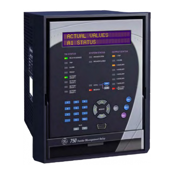
LED Indicators Description The front panel indicators are grouped into three columns. The 750/760 Status column indicates the state of the relay; the System Status column indicates the state of the breaker and the system; and the Output Status column indicates the state of the output relays. -
Page 64: 750/760 Status Led Indicators
750/760 LED Indicators Feeder Management Relay FIGURE 4–1: 750/760 Front Panel 750/760 Status LED • RELAY IN SERVICE: This indicator will be on continuously if the relay is functioning normally and no major self-test errors have been detected. During Indicators... -
Page 65: System Status Led Indicators
Breaker operations performed by 750/760 outputs in response to logic inputs energized with contacts from a local control switch are considered as remote operations. When the 750/760 is in local mode, the local panel is the relay faceplate; everything else is considered remote, even the control switch that might be installed in the same switchgear compartment. -
Page 66: Output Status Led Indicators
Output Status LED The 750/760 has eight (8) output relays: the 1 Trip, 2 Close, and 8 Self-Test Warning relays have fixed operation while the 3 to 7 Auxiliary relays are Indicators configurable. -
Page 67: Relay Messages
Feeder Management Relay Relay Messages Keypad Operation The 750/760 display messages are organized into Main Menus, Pages, and Sub- pages. There are three main menus labeled Setpoints, Actual Values, and Target Messages. Pressing the MENU key followed by the MESSAGE... -
Page 68: Diagnostic Messages
750/760 Relay Messages Feeder Management Relay Pressing the OPEN key will attempt to open the breaker connected to the Trip Relay by closing the contact. Likewise, the CLOSE key will attempt to close the breaker connected to the Close Relay by closing the contact. The OPEN and CLOSE keys only operate when the relay is in local mode;... - Page 69 Occurs when prototype software has been loaded into the relay. Relay Not Ready Minor This warning occurs when the 750/760 OPERATION setpoint not been set to “Ready”. RTC Crystal Minor This warning is caused by a failure of the Real Time Clock circuit.
-
Page 70: Flash Messages
750/760 Relay Messages Feeder Management Relay Flash Messages Flash messages are warning, error, or general information messages displayed in response to certain key presses. The length of time these messages remain displayed can be programmed in S1 RELAY SETUP FRONT PANEL FLASH MESSAGE . - Page 71 750/760 Relay Messages Feeder Management Relay This flash message is displayed while changing the PLEASE ENTER A passcode with the S1 RELAY SETUP PASSCODE CHANGE NON-ZERO PASSCODE setpoint. An attempt was made to change the PASSCODE passcode to “0” when it was already “0”.
-
Page 72: Enervista 750/760 Setup Software Interface
Overview The EnerVista 750/760 Setup software provides a graphical user interface (GUI) as one of two human interfaces to a 750/760 device. The alternate human interface is implemented via the device's faceplate keypad and display (see the first section in this chapter). - Page 73 750/760 EnerVista 750/760 Setup Software Interface Feeder Management Relay FIGURE 4–3: Communications using Rear RS485 Port RS485 COM2 is disabled when the Ethernet option is ordered. NOTE 996711A1.CDR FIGURE 4–4: Communications using Rear Ethernet Port GE Multilin 4–11 http://www.GEmultilin.com...
-
Page 74: Installing The Enervista 750/760 Setup Software
750/760 EnerVista 750/760 Setup Software Interface Feeder Management Relay Installing the EnerVista The following minimum requirements must be met for the EnerVista 750/760 Setup 750/760 Setup Software software to operate on your computer. • Pentium class or higher processor (Pentium II 300 MHz or better recommended) •... - Page 75 EnerVista 750/760 Setup software to the Windows start menu. 11. Click Finish to end the installation. The 750/760 device will be added to the list of installed IEDs in the EnerVista Launchpad window, as shown below.
-
Page 76: Connecting Enervista 750/760 Setup To The Relay
In this example, we will use “Substation 1” as the site name. Click the OK button when complete. The new site will appear in the upper-left list in the EnerVista 750/760 Setup window. Click the Add Device button to define the new device. -
Page 77: Using The Quick Connect Feature
Proceed to Connecting to the Relay on page 4–17 to begin communications. Using the Quick The Quick Connect button can be used to establish a fast connection through the front panel RS232 port of a 750/760 relay. The following window will appear when Connect Feature the Quick Connect button is pressed:... -
Page 78: Configuring Ethernet Communications
NET- menu). WORK CONFIGURATION Click the Read Order Code button to connect to the 750/760 and upload the order code. If an communications error occurs, ensure that the Ethernet communications values correspond to the relay setting values. Click OK when the relay order code has been received. The new device will be added to the Site List window (or Online window) located in the top left corner of the main EnerVista 750/760 Setup window. -
Page 79: Connecting To The Relay
Other setpoint and commands windows can be displayed and edited in a similar manner. Actual values windows are also available for display. These windows can be locked, arranged, and resized at will. Refer to the EnerVista 750/760 Setup Help File for additional information about the using the software. NOTE GE Multilin 4–17... -
Page 80: Working With Setpoints And Setpoint Files
Working with Setpoints and Setpoint Files Engaging a Device The EnerVista 750/760 Setup software may be used in on-line mode (relay connected) to directly communicate with a 750/760 relay. Communicating relays are organized and grouped by communication interfaces and into sites. Sites may contain any number of relays selected from the SR or UR product series. -
Page 81: File Support
In the Setpoint / System Setup dialog box, click on Store to save the values into the 750/760. Click OK to accept any changes and exit the window. Click Cancel to retain previous values and exit. - Page 82 Saving setpoints is also highly recommended before making any setpoint changes or creating new setpoint files. The EnerVista 750/760 Setup window, setpoint files are accessed in the Settings List control bar window or the Files Window. Use the following procedure to download and save setpoint files to a local PC.
- Page 83 ‘750’ or ‘760’ (for example, ‘feeder1.750’). Click Save and OK to complete the process. Once this step is completed, the new file, with a complete path, will be added to the EnerVista 750/760 Setup software environment. e) Upgrading Setpoint Files to a New Revision...
- Page 84 4–23 for instructions on loading this setpoint file into the 750/760. f) Printing Setpoints and Actual Values The EnerVista 750/760 Setup software allows the user to print partial or complete lists of setpoints and actual values. Use the following procedure to print a list of...
- Page 85 The following procedure illustrates how to load setpoints from a file. Before loading a setpoints file, it must first be added to the EnerVista 750/760 Setup environment as described in Adding Setpoints Files to the Environment on page 4–20.
-
Page 86: Upgrading Relay Firmware
Do not proceed unless you have saved the current setpoints. The EnerVista 750/760 Setup software will request the new firmware file. Locate the firmware file to load into the 750/760. The firmware filename has the following format: 27 K 700 A4 . 000 Modification Number (000 = none) A4 = Analog Board file;... -
Page 87: Advanced Enervista 750/760 Setup Features
The EnerVista 750/760 Setup software now prepares the 750/760 to receive the new firmware file. The 750/760 will display a message indicating that it is in Upload Mode. While the file is being loaded into the 750/760, a status box appears showing how much of the new firmware file has been transferred and how much is remaining, as well as the upgrade status. -
Page 88: Waveform Capture (Trace Memory)
The EnerVista 750/760 Setup software can be used to capture waveforms (or view (Trace Memory) trace memory) from the 750/760 relay at the instance of a trip. A maximum of 512 cycles can be captured and the trigger point can be adjusted to anywhere within the set cycles. - Page 89 750/760 Advanced EnerVista 750/760 Setup Features Feeder Management Relay To view the captured waveforms, click the Launch Viewer button. A detailed Waveform Capture window will appear as shown below: CURSOR LINE POSITION TRIGGER TIME & DATE Indicate the cursor line position VECTOR DISPLAY SELECT Display the time &...
- Page 90 750/760 Advanced EnerVista 750/760 Setup Features Feeder Management Relay The following window will appear: Change the Color of each graph as desired, and select other options as required, by checking the appropriate boxes. Click OK to store these graph attributes, and to close the window.
-
Page 91: Data Logger
Waveform Capture described above. Event Recorder The 750/760 event recorder can be viewed through the EnerVista 750/760 Setup software. The event recorder stores generator and system information each time an event occurs (e.g. breaker failure). A maximum of 512 events can be stored, where E512 is the most recent event and E001 is the oldest event. -
Page 92: Modbus User Map
Select Event box. Modbus User Map The EnerVista 750/760 Setup software provides a means to program the 750/760 User Map (Modbus addresses 0180h to 01F7h). Refer to GE Publication GEK- 106473: 750/760 Communications Guide for additional information on the User Map. -
Page 93: Using Enervista Viewpoint With The 750/760
Install the EnerVista Viewpoint software from the GE EnerVista CD. Ensure that the 750/760 device has been properly configured for either serial or Ethernet communications (see previous sections for details). Click the Viewpoint window in EnerVista to log into EnerVista Viewpoint. At this point, you will be required to provide a login and password if you have not already done so. - Page 94 Click the OK button when complete. The new site will appear in the upper-left list in the EnerVista 750/760 Setup window. Click the Add Device button to define the new device.
- Page 95 Using EnerVista Viewpoint with the 750/760 Feeder Management Relay Click the Read Order Code button to connect to the 750/760 device and upload the order code. If an communications error occurs, ensure that communications values entered in the previous step correspond to the relay setting values.
- Page 96 750/760 Using EnerVista Viewpoint with the 750/760 Feeder Management Relay FIGURE 4–11: EnerVista Plug and Play Screens For additional information on EnerVista viewpoint, please visit the EnerVista website at http://www.EnerVista.com. GE Multilin 4–34 http://www.GEmultilin.com...
-
Page 97: Overview
5 Setpoints Overview Setpoints Main Menu The 750/760 has a considerable number of programmable setpoints which makes it extremely flexible. The setpoints have been grouped into a number of pages and sub-pages as shown below. Each page of setpoints (e.g. - Page 98 750/760 Overview Feeder Management Relay MESSAGE SETPOINTS CURRENT See page 5–17. S2 SYSTEM SETUP SENSING BUS VT MESSAGE See page 5–17. SENSING LINE VT MESSAGE See page 5–18. SENSING POWER SYSTEM MESSAGE See page 5–18. FLEXCURVE A MESSAGE See page 5–18.
- Page 99 750/760 Overview Feeder Management Relay 5 AUXILIARY MESSAGE See page 5–31. 6 AUXILIARY MESSAGE See page 5–31. 7 AUXILIARY MESSAGE See page 5–31. END OF PAGE S4 MESSAGE MESSAGE SETPOINTS PHASE See page 5–37. S5 PROTECTION CURRENT NEUTRAL MESSAGE See page 5–43.
-
Page 100: Setpoint Entry Methods
Files can be stored and downloaded for fast, error free entry when a computer is used. To facilitate this process, the GE EnerVista CD with the EnerVista 750/760 Setup software is supplied with the relay. -
Page 101: Common Setpoints
The EnerVista 750/760 Setup software incorporates a facility for programming the relay’s passcode as well as enabling/disabling setpoint access. For example, when an attempt is made to modify a setpoint but access is restricted, the program will prompt the user to enter the passcode and send it to the relay before the setpoint is actually written to the relay. -
Page 102: Logic Diagrams
750/760 Overview Feeder Management Relay “Disabled”, then the feature is not operational. If <ELEMENT_NAME> FUNCTION: “Enabled”, then the feature is operational. <ELEMENT_NAME> FUNCTION: “Trip”, then the feature is operational. When an <ELEMENT_NAME> FUNCTION: output is generated the feature declares a Trip condition, which operates the 1 Trip relay and any other selected output relays, and displays the appropriate trip message. -
Page 103: S1 Relay Setup Passcode
If no keys are pressed for longer than 30 minutes, setpoint access automatically becomes restricted. Removing setpoint access jumper immediately restricts setpoint access. If passcode protection is active but the passcode is not known, contact GE Multilin with the value. ENCRYPTED PASSCODE GE Multilin 5–7 http://www.GEmultilin.com... -
Page 104: Communications
CONFIGURATION NETWORK MESSAGE See page 5–10. CONFIGURATION The 750/760 relay has setpoints to enable communications through its RS232, RS485/422, and Ethernet ports. Setpoints are also provided for configuring DNP communications through one of these ports. The menu is NETWORK CONFIGURATION seen only if the Ethernet option is ordered. - Page 105 • DATA LINK CONFIRM TIMEOUT: Select a desired timeout. If no confirmation response is received within this time, the 750/760 re-sends the frame if retries are still available. • DATA LINK CONFIRM RETRIES: Select the number of retries that will be issued for a given data link frame.
-
Page 106: Clock
• COLD RESTART INHIBIT: When disabled, a cold restart request from a DNP master will cause the 750/760 to be reset. Enabling this setpoint will cause the cold start request to initialize only the DNP sub-module. When is “Disabled”, a cold restart request causes loss of... -
Page 107: Event Recorder
Vs) as well as digital data for the output relays and input contact states. The trace memory data can be downloaded to the EnerVista 750/760 Setup software for display and diagnostics purposes. All data is stored in volatile RAM memory which means that the information is lost when power to the relay is lost. -
Page 108: Data Logger
750/760 S1 Relay Setup Feeder Management Relay • BUFFER ORGANIZATION: Selects the partitioning of waveform capture data storage. The first number indicates the number of events that can be stored in memory. The second number indicates the number of data samples captured per channel for each event. -
Page 109: Front Panel
The data logger samples and records up to eight (8) actual values at user-defined intervals. This recorded data may be downloaded to the EnerVista 750/760 Setup software for display and diagnostics. All data is stored in volatile RAM memory which means that the information is lost when power to the relay is lost. -
Page 110: Default Messages
750/760 S1 Relay Setup Feeder Management Relay Firmware versions 3.70 and higher do not support a keypad beeper as did previous firmware versions. The EnerVista 750/760 Setup software does not support keypad beeper operation. NOTE • FLASH MSG TIME: Flash messages are status, warning, error, or information messages displayed for several seconds in response to certain key presses during setpoint programming. -
Page 111: User Text Messages
750/760 S1 Relay Setup Feeder Management Relay key again while this message is being displayed. The message is now added to the default message list. Default messages can be removed from the default message list, as follows: Allow access to setpoints by installing the setpoint access jumper and entering the correct passcode. -
Page 112: Installation
These setpoints are shown if the Mod 008 Reverse Power option has been ordered with the 750/760 relay. To order this option, please contact GE Multilin with the serial number of the relay. Refer to Reverse Power on page 8–1 for the complete procedure for installing and verifying the Reverse Power element. -
Page 113: S2 System Setup Current Sensing
750/760 S2 System Setup Feeder Management Relay S2 System Setup Current Sensing PATH: SETPOINTS S2 SYSTEM SETUP CURRENT SENSING Range: 1 to 50000 A in steps of 1 CURRENT PHASE CT PRIMARY: SENSING 1000 A Range: 1 to 50000 A in steps of 1... -
Page 114: Line Vt Sensing
750/760 S2 System Setup Feeder Management Relay Line VT Sensing PATH: SETPOINTS S2 SYSTEM SETUP LINE VT SENSING Range: Van, Vbn, Vcn, Vab, Vcb LINE VT VT CONNECTION TYPE: SENSING Range: 50.0 to 240.0 V in steps of 0.1 NOMINAL VT SECONDARY MESSAGE VOLTAGE: 120.0 V... -
Page 115: S3 Logic Inputs
S3 Logic Inputs Overview The 750/760 relay has twenty (20) logic inputs which can be used to operate a variety of logic functions for circuit breaker control, external trips, blocking of protection elements, etc. The relay has ‘contact inputs’ and ‘virtual inputs’ that are combined in a form of programmable logic to facilitate the implementation of various schemes. -
Page 116: Logic Inputs Setup
750/760 S3 Logic Inputs Feeder Management Relay • The same logic function can be invoked both locally via contact input or front panel keypad, and/or remotely via communications. • Panel switches can be replaced entirely by virtual switches to save cost and wiring. -
Page 117: Breaker Functions
750/760 S3 Logic Inputs Feeder Management Relay Value Logic Input Asserted When: Disabled Never Contact Close Contact is closed Contact Open Contact is open Virtual On Virtual input is on Virtual Off Virtual input is off Closed & Von Contact is closed AND virtual input is on Closed &... -
Page 118: Control Functions
750/760 S3 Logic Inputs Feeder Management Relay It is strongly recommended that the Breaker Operation Failure alarm be enabled when either 52a or 52b breaker auxiliary contacts are installed. CAUTION Breaker logic functions must be assigned to Logic Inputs 1 to 14 as they must only be contacts. -
Page 119: User Inputs
750/760 S3 Logic Inputs Feeder Management Relay User Inputs PATH: SETPOINTS S3 LOGIC INPUTS USER INPUTS USER INPUT A(T) Range: 18 alphanumeric characters USER INPUT A USER INPUT A NAME: Press [ ] for more User Input A Range: Input 1 to Input 20, Disabled... -
Page 120: Block Functions
750/760 S3 Logic Inputs Feeder Management Relay Block Functions PATH: SETPOINTS S3 LOGIC INPUTS BLOCK FUNCTIONS Range: Input 1 to Input 20, Disabled BLOCK BLOCK 1 TRIP RELAY: FUNCTIONS Disabled Range: Input 1 to Input 20, Disabled BLOCK 2 CLOSE RELAY:... -
Page 121: Block Overcurrent
750/760 S3 Logic Inputs Feeder Management Relay Block Overcurrent PATH: SETPOINTS S3 LOGIC INPUTS BLOCK OC FUNCTIONS Range: Input 1 to Input 20, Disabled BLOCK OC BLOCK ALL OC: FUNCTIONS Disabled Range: Input 1 to Input 20, Disabled BLOCK PHASE OC:... -
Page 122: Transfer Functions
750/760 S3 Logic Inputs Feeder Management Relay Transfer Functions PATH: SETPOINTS S3 LOGIC INPUTS TRANSFER FUNCTIONS Range: Input 1 to Input 20, Disabled TRANSFER SELECT TO TRIP: FUNCTIONS Disabled Range: Input 1 to Input 20, Disabled UNDERVOLT ON OTHER MESSAGE... -
Page 123: Reclose (760 Only)
Relay Operation a) Description The 750/760 relay is equipped with eight electromechanical output relays: three special purpose (Trip Relay 1, Close Relay 2, and Self-test Warning Relay 8) and five general purpose (Auxiliary Relays 3 to 7). The special purpose relays have fixed operating characteristics and the general purpose relays can be configured by the user. -
Page 124: Relay Operation
750/760 S4 Output Relays Feeder Management Relay Operation feature or a default interval of 2 seconds expires. If neither of the breaker auxiliary contacts 52a nor 52b is programmed to a logic input, the Trip Relay is de- energized after either the delay programmed in the Breaker Failure feature or a default interval of 100 ms after the initiating input resets and the Close Relay is de- energized after 200 ms. -
Page 125: Trip Relay
Trip Relay, thus extending its pulse width. This is for use in applications where the 52 contacts reporting breaker state to the 750/760 are faster than the 52 contacts that are responsible for interrupting coil current. -
Page 126: Close Relay
Close Relay, thus extending its pulse width. This is for use in applications where the 52 contacts reporting breaker state to the 750/760 are faster than the 52 contacts that are responsible for interrupting coil current. -
Page 127: Auxiliary Relays
750/760 S4 Output Relays Feeder Management Relay Auxiliary Relays PATH: SETPOINTS S4 OUTPUT RELAYS 3(7) AUX RELAY Range: 16 alphanumeric characters 3 AUXILIARY RELAY 3 NAME: Auxiliary Range: Energized, De-energized RELAY 3 NON-OPERATED MESSAGE STATE: De-energized Range: Self-Resetting, Latched, Pulsed... -
Page 128: S5 Protection
750/760 S5 Protection Feeder Management Relay Self-Test Warning There are no user-programmable setpoints associated with the Self-Test Warning Relay Relay (Output Relay 8). The logic for this relay is shown below: FIGURE 5–4: Output Relay 8 Self-Test Warning Logic S5 Protection... -
Page 129: Time Overcurrent Curve Characteristics
> 1. Select the appropriate curve shape and multiplier, thus matching the appropriate curve with the protection requirements. The available curves are shown in the table below. Table 5–4: TOC Curve Selections ANSI GE Type IAC Other Extremely Inverse Extremely Inverse Curve A (BS142) - Page 130 750/760 S5 Protection Feeder Management Relay ANSI Curves: The ANSI time overcurrent curve shapes conform to industry standards and the ANSI C37.90 curve classifications for extremely, very, and moderately inverse. The ANSI curves are derived from the following formula: ⎛...
- Page 131 750/760 S5 Protection Feeder Management Relay IEC Curves: For European applications, the relay offers the four standard curves defined in IEC 255-4 and British standard BS142. These are defined as IEC Curve A, IEC Curve B, IEC Curve C, and Short Inverse. The formulae for these curves are: ⎛...
- Page 132 – where: T = trip time (seconds), M = multiplier setpoint, I = input current, = pickup current setpoint, A to E = constants. pickup Table 5–9: GE Type IAC Inverse Curve Constants IAC Curve Shape IAC Extreme Inverse 0.0040 0.6379...
-
Page 133: Phase Current
750/760 S5 Protection Feeder Management Relay Phase Current a) Main Menu PATH: SETPOINTS S5 PROTECTION PHASE CURRENT PHASE PHASE TIME See below CURRENT OVERCURRENT 1 PHASE TIME MESSAGE OVERCURRENT 2 PHASE INST MESSAGE See page 5–39. OVERCURRENT 1 PHASE INST... - Page 134 750/760 S5 Protection Feeder Management Relay corresponding phase input voltage. When voltage restraint is enabled, it is not allowed to change the pickup current setting if the manual close blocking, cold load pickup blocking or autoreclose features are controlling the protection. If the is selected to “None”, this feature is automatically disabled.
- Page 135 750/760 S5 Protection Feeder Management Relay FIGURE 5–7: Phase TOC Logic (2 of 2) c) Phase Instantaneous Overcurrent PATH: SETPOINTS S5 PROTECTION PHASE CURRENT PHASE INST OVERCURRENT 1(2) Range: Disabled, Trip, Trip & AR, PHASE INST PHASE INST OC 1...
- Page 136 750/760 S5 Protection Feeder Management Relay FIGURE 5–8: Phase IOC Logic d) Phase Directional Overcurrent PATH: SETPOINTS S5 PROTECTION PHASE CURRENT PHASE DIRECTIONAL Range: Disabled, Alarm, Latched PHASE PHASE DIRECTIONAL Alarm, Control DIRECTIONAL FUNCTION: Disabled Range: Any combination of 3 to 7...
- Page 137 FIGURE 5–9: Phase A Directional Overcurrent Polarization The 750/760 uses the secure 90° or quadrature connection exclusively for phase directional polarization. An MTA setting of 90° represents a phase current in-phase with its phase voltage, which is leading the polarizing voltage by 90°.
- Page 138 750/760 S5 Protection Feeder Management Relay To increase security for three phase faults very close to the location of the VTs used to measure the polarizing voltage, a voltage memory feature is incorporated. This feature remembers the last measurement of the polarizing voltage which is greater than the value and uses it to determine direction.
-
Page 139: Neutral Current
750/760 S5 Protection Feeder Management Relay FIGURE 5–10: Phase Directional Logic Neutral Current a) Main Menu PATH: SETPOINTS S5 PROTECTION NEUTRAL CURRENT NEUTRAL NEUTRAL TIME See page 5–44. CURRENT OVERCURRENT 1 NEUTRAL TIME MESSAGE See page 5–44. OVERCURRENT 2 NEUTRAL INST MESSAGE See page 5–45. - Page 140 750/760 S5 Protection Feeder Management Relay b) Neutral Time Overcurrent PATH: SETPOINTS S5 PROTECTION NEUTRAL CURRENT NEUTRAL TIME... 1(2) Range: Disabled, Trip, Trip & AR, NEUTRAL TIME NEUTRAL TIME OC 1 Alarm, Latched Alarm, Control OVERCURRENT 1 FUNCTION: Disabled Range: Any combination of 3 to 7...
- Page 141 750/760 S5 Protection Feeder Management Relay c) Neutral Instantaneous OC PATH: SETPOINTS S5 PROTECTION NEUTRAL CURRENT NEUTRAL INST... 1(2) Range: Disabled, Trip, Trip & AR, NEUTRAL INST NEUTRAL INST OC 1 Alarm, Latched Alarm, Control OVERCURRENT 1 FUNCTION: Disabled Range: Any combination of 3 to 7...
- Page 142 750/760 S5 Protection Feeder Management Relay d) Neutral Directional Overcurrent PATH: SETPOINTS S5 PROTECTION NEUTRAL CURRENT NEUTRAL DIRECTIONAL Range: Disabled, Alarm, Latched NEUTRAL NEUTRAL DIRECTIONAL Alarm, Control DIRECTIONAL FUNCTION: Disabled Range: Any combination of 3 to 7 NEUTRAL DIRECTIONAL MESSAGE...
- Page 143 750/760 S5 Protection Feeder Management Relay FIGURE 5–13: Neutral Directional Voltage Polarization The Neutral Directional specific setpoints are described below. • NEUTRAL POLARIZING: If neutral directional control with both voltage and current polarized elements is desired, enter “Dual”. If neutral directional control with only the voltage polarized element is desired, enter “Voltage”.
-
Page 144: Ground Current
750/760 S5 Protection Feeder Management Relay FIGURE 5–14: Neutral Directional Logic Ground Current a) Main Menu PATH: SETPOINTS S5 PROTECTION GROUND CURRENT GROUND GROUND TIME See page 5–49. CURRENT OVERCURRENT GROUND INST MESSAGE See page 5–50. OVERCURRENT GROUND MESSAGE See page 5–51. - Page 145 750/760 S5 Protection Feeder Management Relay b) Ground Time Overcurrent PATH: SETPOINTS S5 PROTECTION GROUND CURRENT GROUND TIME OVERCURRENT Range: Disabled, Trip, Trip & AR, GROUND TIME GND TIME OC Alarm, Latched Alarm, Control OVERCURRENT FUNCTION: Disabled Range: Any combination of 3 to 7...
- Page 146 750/760 S5 Protection Feeder Management Relay c) Ground Instantaneous Overcurrent PATH: SETPOINTS S5 PROTECTION GROUND CURRENT GRND INST OVERCURRENT Range: Disabled, Trip, Trip & AR, GROUND INST GND INST OC Alarm, Latched Alarm, Control OVERCURRENT FUNCTION: Disabled Range: Any combination of 3 to 7...
- Page 147 750/760 S5 Protection Feeder Management Relay d) Ground Directional Overcurrent PATH: SETPOINTS S5 PROTECTION GROUND CURRENT GROUND DIRECTIONAL Range: Disabled, Alarm, Latched GROUND GND DIRECTIONAL Alarm, Control DIRECTIONAL FUNCTION: Disabled Range: Any combination of 3 to 7 GND DIRECTIONAL MESSAGE...
-
Page 148: Sensitive Ground
750/760 S5 Protection Feeder Management Relay caused by system unbalanced voltages or VT ratio errors. For well-balanced systems and 1% accuracy VTs, this setpoint can be as low as 2% of VT nominal voltage. For systems with high-resistance grounding or floating neutrals, this setpoint can be as high as 20%. - Page 149 750/760 S5 Protection Feeder Management Relay b) Sensitive Ground Time Overcurrent PATH: SETPOINTS S5 PROTECTION SENSITIVE GND CURRENT SENSITIVE GND TIME... Range: Disabled, Trip, Trip & AR, SENSITIVE GND SENSTV GND TIME OC Alarm, Latched Alarm, Control TIME OVERCURRENT FUNCTION: Disabled...
- Page 150 750/760 S5 Protection Feeder Management Relay c) Sensitive Ground Instantaneous Overcurrent PATH: SETPOINTS S5 PROTECTION SENSITIVE GND... SENSITIVE GND INST... Range: Disabled, Trip, Trip & AR, SENSITIVE GND SENSTV GND INST OC Alarm, Latched Alarm, Control INST OVERCURRENT FUNCTION: Disabled...
- Page 151 750/760 S5 Protection Feeder Management Relay d) Sensitive Ground Directional Overcurrent PATH: SETPOINTS S5 PROTECTION SENSITIVE GND... SENSITIVE GND DIRECTIONAL Range: Disabled, Alarm, Latched SENSITIVE GND SENSTV GND DIRECTN Alarm, Control DIRECTIONAL FUNCTION: Disabled Range: Any combination of 3 to 7...
- Page 152 750/760 S5 Protection Feeder Management Relay • MIN POLARIZING VOLTAGE: This setpoint affects the voltage element only. As the system zero sequence voltage is used as the polarizing voltage for this element, a minimum level of voltage must be selected to prevent operation caused by system unbalanced voltages or VT ratio errors.
- Page 153 REF relay. A non-linear resistor will be required where the voltage across the inputs would be greater than 2000 V. Refer to Restricted Earth Fault Inputs on page 3–9 for the connections required to use the 750/760 to perform Restricted Earth Fault protection.
- Page 154 750/760 S5 Protection Feeder Management Relay FIGURE 5–21: Restricted Earth Fault Sample Application We have: R = 3.7 Ω, R = 0.954 Ω (assuming 600 feet of #12 wire), and X(%) = impedance of transformer = 7% = 0.07 The rated transformer current through wye windings is given as:...
-
Page 155: Negative Sequence
750/760 S5 Protection Feeder Management Relay ⋅ 13.748 A × 3.7 Ω × 0.954 Ω 311 Ω 4353 V ⋅ ⋅ → use 150 V as value for (EQ 5.16) – ⋅ 150 V × 4353 V 150 V 2246 V –... - Page 156 750/760 S5 Protection Feeder Management Relay b) Negative Sequence Time Overcurrent PATH: SETPOINTS S5 PROTECTION NEGATIVE SEQUENCE NEG SEQUENCE TIME... Range: Disabled, Trip, Trip & AR, NEG SEQUENCE NEG SEQ TIME OC Alarm, Latched Alarm, Control TIME OVERCURRENT FUNCTION: Disabled...
- Page 157 750/760 S5 Protection Feeder Management Relay c) Negative Sequence Instantaneous Overcurrent PATH: SETPOINTS S5 PROTECTION NEGATIVE SEQUENCE NEG SEQUENCE INST... Range: Disabled, Trip, Trip & AR, NEG SEQUENCE NEG SEQ INST OC Alarm, Latched Alarm, Control INST OVERCURRENT FUNCTION: Disabled...
- Page 158 750/760 S5 Protection Feeder Management Relay d) Negative Sequence Directional Overcurrent PATH: SETPOINTS S5 PROTECTION NEGATIVE SEQUENCE NEG SEQUENCE DIR... Range: Disabled, Alarm, Latched NEG SEQUENCE NEG SEQ DIRECTIONAL Alarm, Control DIRECTIONAL FUNCTION: Disabled Range: Any combination of 3 to 7...
-
Page 159: Voltage
750/760 S5 Protection Feeder Management Relay FIGURE 5–25: Negative Sequence Directional Logic e) Negative Sequence Voltage PATH: SETPOINTS S5 PROTECTION NEGATIVE SEQUENCE NEG SEQUENCE VOLTAGE Range: Disabled, Trip, Alarm, Latched NEG SEQUENCE NEG SEQ VOLTAGE Alarm, Control VOLTAGE FUNCTION: Disabled... -
Page 160: Voltage
750/760 S5 Protection Feeder Management Relay FIGURE 5–26: Negative Sequence Voltage Logic Voltage a) Main Menu PATH: SETPOINTS S5 PROTECTION VOLTAGE VOLTAGE See page 5–65. UNDERVOLTAGE 1 MESSAGE See page 5–65. UNDERVOLTAGE 2 LINE MESSAGE See page 5–66. UNDERVOLTAGE 3... - Page 161 750/760 S5 Protection Feeder Management Relay overfrequency, have their own inhibit functions independent of the undervoltage protection features. • Source Transfer Schemes: In the event of an undervoltage, a transfer signal may be generated to transfer a load from its normal source to a standby or emergency power source.
- Page 162 750/760 S5 Protection Feeder Management Relay level is programmable to prevent undesired operation before voltage becomes available. The setpoints for Bus Undervoltage 1 are shown above; the Bus Undervoltage 2 setpoints are identical. FIGURE 5–28: Bus Undervoltage Logic c) Line Undervoltage...
- Page 163 750/760 S5 Protection Feeder Management Relay FIGURE 5–29: Line Undervoltage Logic d) Overvoltage PATH: SETPOINTS S5 PROTECTION VOLTAGE OVERVOLTAGE 1(2) Range: Disabled, Trip, Alarm, Latched OVERVOLTAGE 1 OVERVOLTAGE 1 Alarm, Control FUNCTION: Disabled Range: Any combination of 3 to 7...
- Page 164 NTR DISPLACEMENT MESSAGE RESET: Instantaneous The 750/760 incorporates a Neutral Displacement element, which uses the internally derived 3V value. This protection element requires the three phase Bus VTs to be wye connected. When setting the pickup level for this element, it is important to consider the error in the VT ratio as well as the normal voltage unbalance on the system.
-
Page 165: Frequency
See page 5–71. DECAY The 750/760 can be used as the primary detecting relay in automatic load shedding schemes based on underfrequency. The need for such a relay arises if during a system disturbance, an area becomes electrically isolated from the main system and suffers a generation deficiency due to the loss of either transmission or generation facilities. - Page 166 750/760 S5 Protection Feeder Management Relay b) Underfrequency PATH: SETPOINTS S5 PROTECTION FREQUENCY UNDERFREQ 1(2) Range: Disabled, Trip, Alarm, Latched UNDERFREQ 1 UNDEFREQUENCY 1 Alarm, Control FUNCTION: Disabled Range: Any combination of 3 to 7 UNDEFREQUENCY 1 MESSAGE Auxiliary relays.
- Page 167 750/760 S5 Protection Feeder Management Relay c) Frequency Decay PATH: SETPOINTS S5 PROTECTION FREQUENCY FREQUENCY DECAY Range: Disabled, Trip, Alarm, Latched FREQUENCY FREQ DECAY Alarm, Control DECAY FUNCTION: Disabled Range: Any combination of 3 to 7 FREQ DECAY MESSAGE Auxiliary relays RELAYS (3-7): ----- Range: 0.1 to 5.0 Hz/s in steps of 0.1...
-
Page 168: Breaker Failure
750/760 autoreclose scheme to lockout. To provide user flexibility, the 750/760 has included two programmable delays for the breaker failure function. The timers can be used singularly or in combination with each other. -
Page 169: Reverse Power
±85 to 87° due to reactive loading on the generator. This element is optional and available from GE Multilin as Mod 008. To order, please contact the factory with the serial number of the 750/760 relay. Refer to Reverse Power on page 8–1 for the complete procedure for installing and verifying the... -
Page 170: S6 Monitoring
750/760 S6 Monitoring Feeder Management Relay S6 Monitoring Current Level a) Main Menu PATH: SETPOINTS S6 MONITORING CURRENT LEVEL CURRENT LEVEL PHASE See below. CURRENT NEUTRAL MESSAGE See page 5–75. CURRENT In addition to the conventional overcurrent protection elements that are used for tripping, separate phase and neutral current level detectors are provided for alarm or control purposes. -
Page 171: Power Factor
750/760 S6 Monitoring Feeder Management Relay c) Neutral Current Level PATH: SETPOINTS S6 MONITORING CURRENT LEVEL NEUTRAL CURRENT Range: Disabled, Alarm, Latched NEUTRAL NEUTRAL CURRENT Alarm, Control CURRENT FUNCTION: Disabled Range: Any combination of 3 to 7 NEUTRAL CURRENT MESSAGE... - Page 172 750/760 S6 Monitoring Feeder Management Relay 996710A1.CDR FIGURE 5–38: Capacitor Bank Switching Two independent elements are available for monitoring power factor, each having a pickup and a dropout level. For each element, when the measured power factor becomes more lagging than the pickup level (i.e. numerically less than), the relay operates a user-selected output contact.
-
Page 173: Fault Locator
750/760 S6 Monitoring Feeder Management Relay FIGURE 5–39: Power Factor Logic Fault Locator PATH: SETPOINTS S6 MONITORING FAULT LOCATOR Range: 0.1 to 99.9 km/Miles in steps of FAULT LOCATOR LENGTH OF FEEDER: 0.1 km Range: km, Miles UNITS OF LENGTH: MESSAGE Range: 0.01 to 99.99 Ω... - Page 174 750/760 S6 Monitoring Feeder Management Relay The feeder positive and zero sequence impedances are a constant per unit dis- tance, and Mutual compensation is not required. If the feeder utilizes conductors of different sizes, or more than one physical arrangement of conductors, or shares poles or towers with a parallel feeder, these assumptions are incorrect and errors are introduced.
-
Page 175: Demand
750/760 S6 Monitoring Feeder Management Relay Demand a) Main Menu PATH: SETPOINTS S6 MONITORING DEMAND DEMAND CURRENT See page 5–80. REAL POWER MESSAGE See page 5–81. REACTIVE POWER MESSAGE See page 5–82. APPARENT POWER MESSAGE See page 5–83. Current demand is measured on each phase, and on three phases for real, reactive, and apparent power. - Page 176 750/760 S6 Monitoring Feeder Management Relay • Rolling Demand: This selection calculates a linear average of the quantity (RMS current, real power, reactive power, or apparent power) over the programmed demand time interval, in the same way as Block Interval. The value is updated every minute and indicates the demand over the time interval just preceding the time of update.
- Page 177 750/760 S6 Monitoring Feeder Management Relay c) Real Power Demand PATH: SETPOINTS S6 MONITORING DEMAND REAL POWER Range: Disabled, Alarm, Latched REAL POWER REAL PWR DEMAND Alarm, Control FUNCTION: Disabled Range: Thermal Exponential, Block MEASUREMENT TYPE: MESSAGE Interval, Rolling Demand.
- Page 178 750/760 S6 Monitoring Feeder Management Relay d) Reactive Power Demand PATH: SETPOINTS S6 MONITORING DEMAND REACTIVE POWER Range: Disabled, Alarm, Latched REACTIVE POWER REACTIVE PWR DMND Alarm, Control FUNCTION: Disabled Range: Thermal Exponential, Block MEASUREMENT TYPE: MESSAGE Interval, Rolling Demand.
- Page 179 750/760 S6 Monitoring Feeder Management Relay e) Apparent Power Demand PATH: SETPOINTS S6 MONITORING DEMAND APPARENT POWER Range: Disabled, Alarm, Latched APPARENT POWER APPARENT PWR DMND Alarm, Control FUNCTION: Disabled Range: Thermal Exponential, Block MEASUREMENT TYPE: MESSAGE Interval, Rolling Demand.
- Page 180 750/760 S6 Monitoring Feeder Management Relay Analog Input a) Main Menu PATH: SETPOINTS S6 MONITORING ANALOG INPUT ANALOG INPUT ANALOG INPUT See page 5–84. SETUP ANALOG MESSAGE See page 5–85. THRESHOLD 1 ANALOG MESSAGE See page 5–85. THRESHOLD 2 ANALOG INPUT MESSAGE See page 5–86.
- Page 181 750/760 S6 Monitoring Feeder Management Relay connected to the analog input, then enter “0” for . The relay then A/I MIN VALUE interprets 4 mA as representing 0°C. Intermediate values between the minimum and maximum are scaled linearly. c) Analog Threshold...
- Page 182 750/760 S6 Monitoring Feeder Management Relay FIGURE 5–45: Analog Input Threshold Logic d) Analog Input Rate of Change PATH: SETPOINTS S6 MONITORING ANALOG INPUT ANALOG INPUT RATE 1(2) Range: Disabled, Alarm, Latched ANALOG INPUT A/I RATE 1 Alarm, Control RATE 1...
-
Page 183: Analog Input
750/760 S6 Monitoring Feeder Management Relay ANALOG ANALOG INPUT INPUT ANALOG INPUT RATE (mA) Time (seconds) FIGURE 5–46: Analog Input Rate of Change Measurement Note that connected analog input will still be read and displayed in A2 METERING if both are set to “Disabled”. - Page 184 750/760 S6 Monitoring Feeder Management Relay FIGURE 5–48: Analog Outputs Channel Characteristics Each channel can be programmed to represent a parameter from the following table: Table 5–19: Analog Output Parameters (Sheet 1 of 2) Parameter Name Range / Units Step...
-
Page 185: Overfrequency
750/760 S6 Monitoring Feeder Management Relay Table 5–19: Analog Output Parameters (Sheet 2 of 2) Parameter Name Range / Units Step Defaults Channel Type Min. Max. Ground Current Angle 0 to 359° Lag Polarizing Current 0 to 65535 Amps 2000 Polarizing Current Angle 0 to 359°... -
Page 186: Equipment
750/760 S6 Monitoring Feeder Management Relay Note that the system frequency will still be measured and displayed in A2 METERING if both the Overfrequency and Underfrequency functions are set to FREQ “Disabled”. FIGURE 5–49: Overfrequency Logic Equipment a) Main Menu... - Page 187 750/760 S6 Monitoring Feeder Management Relay FIGURE 5–50: Trip Counter Logic c) Arcing Current PATH: SETPOINTS S6 MONITORING EQUIPMENT ARCING CURRENT Range: Disabled, Alarm, Latched ARCING CURRENT ARCING CURRENT Alarm, Control FUNCTION: Disabled Range: Any combination of 3 to 7...
- Page 188 750/760 S6 Monitoring Feeder Management Relay Breaker Trip Contacts Extinguished Command Part Total Area = Breaker Arcing Current (kA x cycle) Programmable 100 ms Start Delay Start Stop Integration Integration ARCING.CDR FIGURE 5–51: Arcing Current Measurement FIGURE 5–52: Arcing Current Logic GE Multilin 5–92...
- Page 189 750/760 S6 Monitoring Feeder Management Relay d) Breaker Operation PATH: SETPOINTS S6 MONITORING EQUIPMENT BREAKER OPERATION Range: Disabled, Alarm, Latched BREAKER BRKR OPERATION Alarm, Control OPERATION FUNCTION: Disabled Range: Any combination of 3 to 7 BRKR OPERATION MESSAGE Auxiliary relays RELAYS (3-7): ----- Range: 0.03 to 1.00 s in steps of 0.01...
- Page 190 750/760 S6 Monitoring Feeder Management Relay e) Coil Monitor PATH: SETPOINTS S6 MONITORING EQUIPMENT COIL MONITOR 1(2) Range: Any combination COIL MONITOR 1 COIL MON 1 NAME: alphanumeric characters. Trip Coil Monitor Range: Disabled, Alarm, Latched COIL MON 1 MESSAGE...
- Page 191 MESSAGE DELAY: 10 s The 750/760 detects a VT fuse failure when there are significant levels of negative sequence voltage without correspondingly significant levels of negative sequence current measured at the output CTs. Also, if there is not a significant amount of positive sequence voltage when there is positive sequence current then it could indicate that all the VT fuses have been pulled or the VTs have been racked out.
-
Page 192: Pulse Output
INTERVAL: 10.0 Mvarh The 750/760 can operate selected auxiliary relays after an adjustable interval for the quantities shown above. Pulses occur at the end of each programmed interval. Upon power up of the relay the Pulse Output function, if enabled, will continue from where it was at loss of control power. -
Page 193: S7 Control
750/760 S7 Control Feeder Management Relay S7 Control Setpoint Groups PATH: SETPOINTS S7 CONTROL SETPOINT GROUPS Range: Group 1, Group 2, Group 3, SETPOINT ACTIVE SETPOINT Group 4 GROUPS GROUP: Group 1 Range: Group 1, Group 2, Group 3, EDIT SETPOINT GROUP:... - Page 194 750/760 S7 Control Feeder Management Relay FIGURE 5–57: Setpoint Control (1 of 3) FIGURE 5–58: Setpoint Control (2 of 3) GE Multilin 5–98 http://www.GEmultilin.com...
- Page 195 750/760 S7 Control Feeder Management Relay FIGURE 5–59: Setpoint Control (3 of 3) Each setpoint group includes the selection of Auxiliary Output Relays 3 to 7 that can be operated by the protection features. As these relays are hard- wired to external equipment, the selection should only be changed from CAUTION that in setpoint Group 1 with considerable care.
-
Page 196: Synchrocheck
750/760 S7 Control Feeder Management Relay Synchrocheck PATH: SETPOINTS S7 CONTROL SYNCHROCHECK Range: Disabled, Alarm, Latched SYNCHROCHECK SYNCHROCHECK Alarm, Control FUNCTION: Disabled Range: Any combination of 3 to 7 SYNCHROCHECK MESSAGE Auxiliary relays RELAYS (3-7): ----- Range: Off, DB&DL, LL&DB, DL&LB,... - Page 197 750/760 S7 Control Feeder Management Relay For the setpoints, enter the voltage LIVE BUS MIN VOLTAGE LIVE LINE MIN VOLTAGE magnitude as a fraction of the bus or line VT input nominal voltage. If the bus or line voltage rises above the respective setting, the single bus or line voltage input used for synchrocheck is established as ‘live’, or energized.
-
Page 198: Manual Close Blocking
Group 4, Active Group GROUP: Active Group The 750/760 can be programmed to block instantaneous overcurrent elements and raise the pickup level of time overcurrent elements when a manual breaker close is performed. This prevents optimally set overcurrent elements from erroneously operating on startup due to inrush currents. - Page 199 750/760 S7 Control Feeder Management Relay FIGURE 5–61: Manual Close Blocking Logic GE Multilin 5–103 http://www.GEmultilin.com...
-
Page 200: Cold Load Pickup
Group 4, Active Group GROUP: Active Group The 750/760 can be programmed to block instantaneous overcurrent elements and to raise the pickup level of time overcurrent elements when a cold load condition is detected. Under normal operating conditions, the actual load on a feeder is less than the maximum connected load, since not all consumers require maximum load at the same time. - Page 201 750/760 S7 Control Feeder Management Relay NORMAL TRIP SETTING PICKUP PICKUP OUTAGE Time (seconds) LOAD ENERGIZED FIGURE 5–62: Cold Load Pickup A cold load condition is initiated and overcurrent settings are altered when all phase currents drop below 5% of the nominal current for an amount of time greater than setpoint.
-
Page 202: Undervoltage Restoration
750/760 S7 Control Feeder Management Relay Undervoltage Restoration PATH: SETPOINTS S7 CONTROL UNDERVOLTAGE RESTORATION Range: Disabled, Alarm, Latched UNDERVOLTAGE UNDERVOLT RESTORE Alarm, Control RESTORATION FUNCTION: Disabled Range: Any combination of 3 to 7 UNDERVOLT RESTORE MESSAGE Auxiliary relays RELAYS (3-7): -----... -
Page 203: Underfrequency Restore
750/760 S7 Control Feeder Management Relay Underfrequency Restore PATH: SETPOINTS S7 CONTROL UNDERFREQUENCY RESTORATION Range: Disabled, Alarm, Latched UNDERFREQUENCY UNDERFREQ RESTORE Alarm, Control RESTORATION FUNCTION: Disabled Range: Any combination of 3 to 7 UNDERFREQ RESTORE MESSAGE Auxiliary relays RELAYS (3-7): ----- Range: 0.00 to 1.25 x VT in steps of... -
Page 204: Transfer Scheme
Bus Tie breaker. The normal system configuration is with both incoming breakers closed and the bus tie breaker open. The transfer scheme implemented in the 750/760 is known as Open Transfer, with an “Open before Close” operation sequence; this means that the faulty incomer is removed from service before the tie breaker is closed. - Page 205 750/760 S7 Control Feeder Management Relay The transfer scheme minimizes the effect of outages on one of the incoming supplies by opening the incoming breaker connected to that supply, and then re- energizing the dead bus by closing the bus tie breaker to transfer the dead bus to the live source.
- Page 206 94). In addition to the local 750/760 relays, the signal triggering the transfer sequence can be originated from the upstream protection. An auxiliary contact from the tripping device (94) is fed to one of the 750/760 logic inputs, which is programmed as “Source Trip”.
- Page 207 TRANSFER NOT READY will be displayed by the relays. Once a condition has caused the 750/760 relay on Incomer 1 (Relay 1) to initiate a transfer, the following sequence of events will take place: Relay 1 trips Incomer 1 breaker (Breaker 1).
- Page 208 750/760 S7 Control Feeder Management Relay • Logic inputs for transfer functions: Refer to Transfer Functions on page 5–26 for additional information. These are the settings that relate the Logic Inputs defined above, with their specific functions within the scheme.
- Page 209 DEAD LINE MIN VOLTAGE level of decayed voltage above which transfers are inhibited. A normal setting for this element is about 0.25 of pickup of nominal voltage. Because the 750/ 760 measures a single phase-phase voltage, these values should be multiplied...
- Page 210 750/760 S7 Control Feeder Management Relay The Logic Inputs for Incomers 1 and 2 and the Bus Tie relays are programmed as follows. Note that the input number matches the wiring shown on the DC schematics. It is not necessary that the specific inputs are programmed as shown, but field connections must match the logic functions.
- Page 211 750/760 S7 Control Feeder Management Relay FIGURE 5–66: Transfer Scheme One Line Diagram GE Multilin 5–115 http://www.GEmultilin.com...
- Page 212 750/760 S7 Control Feeder Management Relay FIGURE 5–67: Transfer Scheme Incomer No. 1 DC Schematic GE Multilin 5–116 http://www.GEmultilin.com...
- Page 213 750/760 S7 Control Feeder Management Relay FIGURE 5–68: Transfer Scheme Incomer No. 2 DC Schematic GE Multilin 5–117 http://www.GEmultilin.com...
- Page 214 750/760 S7 Control Feeder Management Relay FIGURE 5–69: Transfer Scheme Bus Tie Breaker DC Schematic GE Multilin 5–118 http://www.GEmultilin.com...
- Page 215 750/760 S7 Control Feeder Management Relay FIGURE 5–70: Transfer Scheme Incomer No. 1 Logic GE Multilin 5–119 http://www.GEmultilin.com...
- Page 216 750/760 S7 Control Feeder Management Relay FIGURE 5–71: Transfer Scheme Incomer No. 2 Logic GE Multilin 5–120 http://www.GEmultilin.com...
- Page 217 750/760 S7 Control Feeder Management Relay FIGURE 5–72: Transfer Scheme Bus Tie Breaker Logic GE Multilin 5–121 http://www.GEmultilin.com...
-
Page 218: Autoreclose (760 Only)
750/760 S7 Control Feeder Management Relay Autoreclose (760 only) a) Main Menu PATH: SETPOINTS S7 CONTROL AUTORECLOSE AUTORECLOSE SCHEME SETUP See page 5–123. RATE MESSAGE See page 5–126. SUPERVISION CURRENT MESSAGE See page 5–126. SUPERVISION ZONE MESSAGE See page 5–127. - Page 219 750/760 S7 Control Feeder Management Relay Reclosure 1 setpoint, the shot counter is incremented and a breaker closure is initiated using the ‘2 Close’ output contact. At the same time, overcurrent element characteristics are modified according to the Reclosure 1 setpoints.
- Page 220 750/760 S7 Control Feeder Management Relay • MAX NUMBER OF RECLOSURE SHOTS: This setpoint specifies the number of reclosures that should be attempted before reclosure lockout occurs. The dead time and overcurrent characteristics for each reclosure shot are entered in the...
- Page 221 750/760 S7 Control Feeder Management Relay FIGURE 5–73: Autoreclose Scheme Setup Logic GE Multilin 5–125 http://www.GEmultilin.com...
- Page 222 750/760 S7 Control Feeder Management Relay c) Autoreclose Rate Supervision PATH: SETPOINTS S7 CONTROL AUTORECLOSE RATE SUPERVISION Range: Disabled, Alarm, Latched RATE RATE SUPERVISION Alarm, Control SUPERVISION FUNCTION: Disabled Range: Any combination of the 3 to 7 RATE SUPERVISION MESSAGE...
- Page 223 750/760 S7 Control Feeder Management Relay The current supervision feature is used to limit breaker wear. When fault current exceeds user-programmed levels, it reduces the number of reclose shots permitted. Once a reclose sequence is initiated, the maximum current measured on any phase is compared to the setpoint current levels.
- Page 224 750/760 S7 Control Feeder Management Relay The 760 autoreclose scheme can be programmed to maintain coordination of overcurrent elements with a downstream recloser. If a downstream recloser is programmed to use different protection settings for different reclose shots, it may be necessary to change the protection setpoints on the 760 each time the recloser operates.
- Page 225 750/760 S7 Control Feeder Management Relay FIGURE 5–76: Autoreclose Zone Coordination Logic GE Multilin 5–129 http://www.GEmultilin.com...
- Page 226 750/760 S7 Control Feeder Management Relay f) Reclosure Shots 1 to 4 PATH: SETPOINTS S7 CONTROL AUTORECLOSE RECLOSURE 1(4) Range: 0.00 to 300.00 s in steps of 0.01 RECLOSURE 1 DEADTIME BEFORE RECLOSURE: 0.50 s Range: Enabled, Disabled PHASE INST OC 1...
- Page 227 750/760 S7 Control Feeder Management Relay FIGURE 5–77: Autoreclosure Shots 1 to 4 Logic g) Autoreclosure Application Example Utility statistics indicate that a large percentage of feeder faults (about 80%) are of a transient nature. Typically, once the feeder is tripped an autorecloser automatically reclosures the feeder breaker after a short time delay.
- Page 228 750/760 S7 Control Feeder Management Relay A typical autoreclose scheme as implemented in the 760 would respond to faults as follows: With the breaker closed and protection enabled, a transient fault produces a current above the pickup of both Instantaneous Overcurrent 1 (lo-set) and Time Overcurrent 1 elements.
-
Page 229: S8 Testing
750/760 S8 Testing Feeder Management Relay S8 Testing Output Relays PATH: SETPOINTS S8 TESTING OUTPUT RELAYS Range: Enabled, Disabled OUTPUT RELAYS FORCE OUTPUT RELAYS FUNCTION: Disabled Range: Energized, De-energized FORCE 1 TRIP MESSAGE RELAY: De-energized Range: Energized, De-energized FORCE 2 CLOSE... -
Page 230: Pickup Test
The relay provides the ability to operate any or all of the 3 to 7 Auxiliary output relays upon the pickup of any protection element. The pickup test feature is especially useful for automated testing. Through a 750/760 output contact, test equipment can monitor a pickup threshold. -
Page 231: Simulation
750/760 S8 Testing Feeder Management Relay Simulation a) Main Menu PATH: SETPOINTS S8 TESTING SIMULATION SIMULATION SETUP See page 5–136. PREFAULT MESSAGE See page 5–137. VALUES FAULT MESSAGE See page 5–137. VALUES POST FAULT MESSAGE See page 5–138. VALUES When in Simulation Mode, the normal protection and control features are not operational. - Page 232 750/760 S8 Testing Feeder Management Relay setpoint to “Prefault”. The relay replaces the normal AC inputs with those pro- grammed on the setpoint page. Logic inputs, except for the PREFAULT VALUES 52a and 52b contacts, are monitored normally throughout the simulation. The relay’s simulation of a circuit breaker is indicated by the status of the Breaker...
- Page 233 750/760 S8 Testing Feeder Management Relay An operator can use the simulation feature to provide a complete functional test of the relay’s protection features, except for the measurement of external input values. As this feature may be used for on-site testing, provision is made to block the operation of the output relays so the operation of other equipment is prevented.
-
Page 234: Factory Service
750/760 S8 Testing Feeder Management Relay Range: 0.00 to 20.00 x CT in steps of PHASE C CURRENT MESSAGE 0.01 LEVEL: 1.00 x CT Range: 0 to 359° Lag in steps of 1 PHASE C CURRENT MESSAGE POSITION: 300° Lag Range: 0.00 to 20.00 x CT in steps of... -
Page 235: Actual Values
Actual values may be accessed as follows: Front panel, using the keys and display. Front program port, and a portable computer running the EnerVista 750/760 Setup software supplied with the relay. Rear RS485/RS422 COM 1 port or RS485 COM 2 port with a SCADA system running user-designed software. - Page 236 750/760 Overview Feeder Management Relay FREQUENCY MESSAGE See page 6–11. SYNCHRONIZING MESSAGE See page 6–11. VOLTAGE POWER MESSAGE See page 6–12. ENERGY MESSAGE See page 6–13. DEMAND MESSAGE See page 6–13. ANALOG INPUT MESSAGE See page 6–14. END OF PAGE A2...
- Page 237 750/760 Overview Feeder Management Relay FIGURE 6–1: Actual Values Block Diagram (1 of 2) GE Multilin 6–3 http://www.GEmultilin.com...
- Page 238 750/760 Overview Feeder Management Relay FIGURE 6–2: Actual Values Block Diagram (2 of 2) GE Multilin 6–4 http://www.GEmultilin.com...
-
Page 239: Hardware Inputs
750/760 A1 Status Feeder Management Relay A1 Status Virtual Inputs PATH: ACTUAL VALUES A1 STATUS VIRTUAL INPUTS Range: 0 to 20 Virtual Inputs VIRTUAL INPUTS 2 VIRTUAL INPUTS ARE ACTIVE Range: On, Off. Reflects the user- Logic Input 1 programmed name. -
Page 240: Last Trip Data
750/760 A1 Status Feeder Management Relay Last Trip Data PATH: ACTUAL VALUES A1 STATUS LAST TRIP DATA Range: Date in format shown LAST TRIP DATA DATE OF LAST TRIP: Nov 17 2003 Range: Time in format shown TIME OF LAST TRIP: MESSAGE 12:34:56.789... -
Page 241: Clock
750/760 A2 Metering Feeder Management Relay The data for ten faults detected by overcurrent elements is stored under headings beginning with . This information cannot be cleared; data for new FAULT LOCATION 0 events is always stored as fault 0. The data for each previous fault is shifted to the next highest number, and Event 9 is discarded. - Page 242 750/760 A2 Metering Feeder Management Relay system cycle and perform protection and monitoring functions. Displayed metered quantities are updated approximately three (3) times a second for readability. All phasors and symmetrical components are referenced to the A-N voltage phasor for wye-connected VTs;...
-
Page 243: Current
750/760 A2 Metering Feeder Management Relay Current PATH: ACTUAL VALUES A2 METERING CURRENT Range: 0 to 65535 A CURRENT Amps Range: 0 to 2000% % OF LOAD-TO-TRIP: MESSAGE Range: 0 to 65535 A AVERAGE CURRENT: MESSAGE Range: 0 to 65535 A, 0 to 359° Lag... -
Page 244: Voltage
750/760 A2 Metering Feeder Management Relay displays the calculated negative-sequence current RMS phasor NEG SEQ CURRENT as given by: for ABC phase sequence --------------------------------------- (EQ 6.4) for ACB phase sequence --------------------------------------- displays the calculated zero-sequence current RMS ZERO SEQ CURRENT phasor: (EQ 6.5) -
Page 245: Frequency
750/760 A2 Metering Feeder Management Relay displays the calculated average of the RMS phase AVERAGE PHASE VOLTAGE voltages given by: (EQ 6.7) -------------------------------------------------------- displays the calculated neutral RMS phasor given by: NEUTRAL VOLTAGE (EQ 6.8) shows the calculated positive-sequence voltage RMS phasor:... -
Page 246: Power
750/760 A2 Metering Feeder Management Relay Power PATH: ACTUAL VALUES A2 METERING POWER Range: –30000 to 30000 kW. See the POWER 3Φ REAL POWER: table below for details. 0.0 MW Range: –30000 to 30000 kvar. See the 3Φ REACTIVE POWER: MESSAGE table below for details. -
Page 247: Energy
Power quantities in the positive direction are added to the positive values; power quantities in the opposite direction are added to the negative values. The 750/760 is not a revenue class meter and cannot be used for billing purposes. NOTE... -
Page 248: Analog Input
750/760 A2 Metering Feeder Management Relay demand time interval, the maximum demand since the last maximum demand reset, and the time and date stamp of this maximum demand value. Maximum demand quantities can be reset to zero with the S1 RELAY SETUP CLEAR DATA setpoint command. -
Page 249: A3 Maintenance
750/760 A3 Maintenance Feeder Management Relay A3 Maintenance Trip Counters PATH: ACTUAL VALUES A3 MAINTENANCE TRIP COUNTERS Range: 0 to 65535 TRIP COUNTERS BREAKER TRIPS: Range: 0 to 65535 GND OC TRIPS: MESSAGE Range: 0 to 65535 SENSTV GND OC TRIPS:... -
Page 250: A4 Event Recorder
ANALOG INPUT: 0 μA The 750/760 has an event recorder which runs continuously, capturing and storing the last 128 events. All event recorder information is stored in non-volatile memory so the information is maintained after losing relay control power. The last 128 events are displayed from newest to oldest event. - Page 251 750/760 A4 Event Recorder Feeder Management Relay Event information is gathered at the instant the event occurs; as such, the current and voltage readings may reflect the transient nature of the event as opposed to steady state values. All messages pertaining to phase voltages AN, BN, and CN are only displayed if is programmed to “Wye”.
- Page 252 750/760 A4 Event Recorder Feeder Management Relay Table 6–3: Cause of Events General Event Causes Autoreclose Reset Breaker Closed Breaker Not Breaker Open Clear Energy Use Connected Clear Event Record Clear Max Demand Close Breaker Cls From Transfer Control Power Off...
-
Page 253: Last Reset Date
Range: Displays the manufacture date MANUFACTURING DATE: in the format shown. Nov 17 2004 This page specifies hardware revision and configuration, software revision, and serial number. This information is primarily intended for GE Multilin service personnel. GE Multilin 6–19 http://www.GEmultilin.com... -
Page 254: Calibration Dates
DATES DATE: Nov 17 2004 Range: Displays the last calibration LAST CALIBRATION date in the format shown. DATE: Nov 17 2004 This information is primarily intended for GE Multilin service personnel. GE Multilin 6–20 http://www.GEmultilin.com... -
Page 255: Safety Precautions
300 V DC. CAUTION Requirements The following procedures can be used to verify the proper operation of the 750/760 Feeder Management Relay. Although not a total functional verification, the tests in this chapter check the major operating points. Before commissioning the relay, users should read Chapter 3 which provides important information about wiring, mounting, and safety concerns. -
Page 256: Conventions
750/760 Overview Feeder Management Relay The setpoints considered for the measurement of parameters and the operation of features are shown on the logic diagrams. All settings must be set to the application requirement by the user before beginning the tests. To facilitate testing it is recommended that all functions be initially set to “Disabled”. -
Page 257: Installation Checks
1 minute to 2 hours, and from 0 to 20 mA. Optional: • PC running the EnerVista 750/760 Setup software. Installation Checks Check the relay phase current inputs, specified on the nameplate, are correct for the connected current transformers. - Page 258 750/760 Overview Feeder Management Relay START START TRIGGER ± STOP 1 TRIP ± TRIGGER ± INTERVAL 2 CLOSE Vcom TIMING DEVICE φ 3 VARIABLE SOURCE 3 ALARM Ω ± ± ± ± 750/760 MULTIMETER ± ± POWER MULTIMETER ANALOG INPUT...
-
Page 259: Inputs/Outputs
750/760 Inputs/Outputs Feeder Management Relay Inputs/Outputs Logic / Virtual Inputs 1 a) Actual Values Display to 14 For these first tests, the setpoints should be programmed INPUT 1 (14) ASSERTED LOGIC as “Closed | Von”. Under the A1 STATUS VIRTUAL INPUTS... - Page 260 750/760 Inputs/Outputs Feeder Management Relay 4.6. Repeat steps 4.3 through 4.5 for all functions programmed to be asserted by a Contact Open input. setpoints set to “Virtual On”: INPUT ASSERTED LOGIC 5.1. Check that there is no logic input diagnostic message on the display.
- Page 261 750/760 Inputs/Outputs Feeder Management Relay setpoints set to “Closed & Voff”: INPUT ASSERTED LOGIC 8.1. Check that there is no logic input diagnostic message on the display. 8.2. Set the monitored contact for the logic input programmed in setpoint message User Input A Source to the open state and the virtual input to the on state.
- Page 262 750/760 Inputs/Outputs Feeder Management Relay 10.5. Set the monitored contact to the closed state and the virtual input to the on state. Check that the diagnostic message is removed from the display with the Auxiliary LED and relay deactivated. 10.6. Repeat steps 10.3 through 10.5 for all functions programmed to be asserted by a Open &...
- Page 263 750/760 Inputs/Outputs Feeder Management Relay 13.3. Set the monitored contact to the closed state and leave the virtual input in the on state. Check that the diagnostic message, the Auxiliary LED and relay remain activated. 13.4. Leave the monitored contact in the closed state and put the virtual input in the off state.
- Page 264 750/760 Inputs/Outputs Feeder Management Relay 16.3. Leave the monitored contact in the closed state and put the virtual input in the off state. Check that the diagnostic message is removed from the display with the Auxiliary LED and relay deactivated.
-
Page 265: Virtual Inputs 15 To 20
750/760 Metering Feeder Management Relay d) User Input A Function Set to “Trip” The procedure to test this element is identical to that outlined for User Input A Function setpoint set to Alarm, with the following exceptions. The Trip Relay and LED will activate along with the Auxiliary Relay and LED. -
Page 266: Voltage Metering
750/760 Metering Feeder Management Relay The relevant actual values displays are located under subheading A2 METERING and are: CURRENT (Magnitude) A: B: C: (Magnitude) AVERAGE CURRENT: (Phasor) PHASE A CURRENT: (Phasor) PHASE B CURRENT: (Phasor) PHASE C CURRENT: (Phasor) NEUTRAL CURRENT:... - Page 267 750/760 Metering Feeder Management Relay The relevant actual values displays are located under subheading A2 METERING and are: VOLTAGE (Magnitude) AB: BC: CA: (Magnitude) AVERAGE LINE VOLTAGE: (Magnitude) (not available when connected Delta) AN: BN: CN: (Magnitude) (not available when connected Delta)
-
Page 268: Power Metering
750/760 Metering Feeder Management Relay (Phasor) SYNCHRO VOLTAGE: SYNCHRO FREQ: SYNCHRO DELTA DF: DV: DF: Inject voltage of various magnitudes and frequencies into the line voltage input and verify the displays. Power Metering a) Real Power and Watthours For these tests, refer to the figures on page 7–4 for test connections. The expected accuracy is as follows: Real Power: ±1% of full scale at currents 5 to 199% of nominal and voltages... -
Page 269: Demand Metering
Both of these measurements start with the first interval of the day at 12:00:00.000 midnight. To synchronize, preset the injection levels, then turn the current off. Select the relay display (not the EnerVista 750/760 Setup software) to . Apply the test A1 STATUS... - Page 270 750/760 Metering Feeder Management Relay A2 METERING DMND PHASE C CURRENT LAST PHASE C CURRENT DMND A2 METERING DMND PHASE C CURRENT MAX PHASE C CURRENT DMND A2 METERING DMND PHASE B CURRENT MAX PHASE C CURRENT DATE A2 METERING...
-
Page 271: Protection Schemes
750/760 Protection Schemes Feeder Management Relay The relevant actual values displays are shown below: A2 METERING DMND REACTIVE PWR LAST REACTIVE PWR DMND A2 METERING DMND REACTIVE PWR MAX REACTIVE PWR DMND A2 METERING DMND REACTIVE PWR MAX REACTIVE PWR DATE... -
Page 272: Phase Overcurrent
750/760 Protection Schemes Feeder Management Relay Once one of the above strategies is selected, the following procedures are used to test protection elements. Phase Overcurrent a) Phase TOC 1 For these tests, refer to the figures on page 7–4 for test connections. - Page 273 750/760 Protection Schemes Feeder Management Relay Turn current off. The following procedure checks indications and operations caused by a Control function: Inject current to cause a pickup and wait until the element times-out. Check that any output relays programmed to operate (as well as their associated LED indicators) operate.
- Page 274 750/760 Protection Schemes Feeder Management Relay Apply three-phase nominal voltage to the relay. Inject current below the pickup level into Phase A and slowly increase until the Pickup LED is on. Note the pickup value is the pickup current of the Curve in use.
- Page 275 750/760 Protection Schemes Feeder Management Relay Slowly reduce the Phase A current until the Pickup LED goes out. Note the dropout level, which should be 2% of CT less than pickup when pickup CT or ≤ 97 to 98% of pickup when pickup >...
- Page 276 750/760 Protection Schemes Feeder Management Relay Ia LAGS Van PHASE VOLTAGE 270° 300° 330° 0° 30° 60° 90° 120° 150° 180° 210° 240° 270° 90° 60° 30° 0° 330° 300° 270° 180° 210° 240° 270° 300° 330° 0° 30° 60°...
-
Page 277: Neutral Overcurrent
750/760 Protection Schemes Feeder Management Relay Continue to increase the lagging angle until the alarm is again raised. The Phase A current should be lagging the polarizing voltage by an angle of 270° ±2°. Continue to increase the angle until the Phase A current is once again in phase with the polarizing voltage. - Page 278 750/760 Protection Schemes Feeder Management Relay Inject current to cause a pickup. Assert a logic input to provide a “Block Neutral Inst 2”. The Pickup LED should immediately go out. Repeat Steps 1 and 2 for logic inputs “Block Neutral O/C”, “Block All O/C” and “Block 1 Trip Relay”...
- Page 279 750/760 Protection Schemes Feeder Management Relay FIGURE 7–5: Neutral Directional Test Connection for Polarizing Current The following description presents angles with reference to the polarizing current. NOTE Set a current of 0.2 of nominal and inject into the ground current input (Termi- nals G10 and H10).
-
Page 280: Ground Overcurrent
750/760 Protection Schemes Feeder Management Relay original angle. The block alarm should remain throughout the rotation as the current polarized element is still blocking. Increase the angle of the ground current lagging 3I current until the currents are in-phase. The block alarm should remain. -
Page 281: Negative-Sequence Overcurrent And Voltage
750/760 Protection Schemes Feeder Management Relay e) Sensitive Ground IOC The procedure to test this element is identical to that outlined in Phase IOC 1 on page 7–20, except that the current is injected into the sensitive ground input terminals, and the element is not subject to the “phases required for operation”, “linear reset timing”, and “voltage restrained time overcurrent”... -
Page 282: Voltage
750/760 Protection Schemes Feeder Management Relay d) Negative-Sequence Voltage For Wye VTs, use the test connections specified in FIGURE 7–1: Relay Test Wiring – Wye Connection on page 7–4. A negative sequence voltage can be created by injecting a single phase voltage or a set of three single-phase voltages with a known negative sequence component. - Page 283 750/760 Protection Schemes Feeder Management Relay Repeat Steps 1 through 4 except adjust V and V in turn. The following procedure checks Pickup with Two Phases For Operation: Inject V = nominal voltage and V = a voltage between the MIN OPERAT- and the pickup voltage into the bus voltage input of the relay.
-
Page 284: Voltage
750/760 Protection Schemes Feeder Management Relay Continue to lower V until the Pickup LED goes out. This is the MIN OPERATING minus 2% of VT. VOLTAGE Raise V until the Pickup LED comes on, and continue to increase until the indicator goes out. - Page 285 750/760 Protection Schemes Feeder Management Relay Raise the voltage until the Pickup LED comes on, and continue to increase until the indicator goes out. This is the reset voltage, which should be the pickup value plus 2% of VT. The procedures for testing Indications and Operations are the same as those outlined for Phase TOC 1 on page 7–18.
- Page 286 750/760 Protection Schemes Feeder Management Relay f) Overvoltage (Delta VTs only) To test Overvoltage for Delta VTs, use the test connections specified in FIGURE 7–2: Relay Test Wiring – Delta Connection on page 7–4. The following procedure tests Pickup with One Phase For Operation: Inject V = 0 into the bus voltage input of the relay.
-
Page 287: Frequency
750/760 Protection Schemes Feeder Management Relay Repeat Steps 1 and 2 for logic input “Block 1 Trip Relay” as required. The following procedure tests element Timing: Connect the Stop Trigger. Preset the neutral (residual) voltage to be 150% of the pickup setting. - Page 288 750/760 Protection Schemes Feeder Management Relay Slowly increase the frequency until the Pickup LED goes out. Note the dropout level, which should be the pickup plus 0.03 Hz. The following procedure tests Blocking From Logic Inputs: Inject voltage and current above minimum at a frequency to cause a pickup.
-
Page 289: Breaker Failure
750/760 Protection Schemes Feeder Management Relay With the V voltage at a level well above the Minimum Operating Voltage level, increase I to a level well above the Minimum Operating Current level. Currents and I should be well below the Minimum Operating Current level. Starting... -
Page 290: Reverse Power
750/760 Monitoring Feeder Management Relay cannot be performed by the breaker. The element should not generate an output. Reverse Power To test the Reverse Power element, use the test connections specified in FIGURE 7– 1: Relay Test Wiring – Wye Connection or FIGURE 7–2: Relay Test Wiring – Delta Connection on page 7–4. -
Page 291: Fault Locator
750/760 Monitoring Feeder Management Relay Set the Delay timer to the required setting. The following procedure checks the Phase Current Level Timing: Set the test source to a current at least 110% of pickup. Turn off and reset the timer. -
Page 292: Demand Monitoring
750/760 Monitoring Feeder Management Relay Program the test set with the following fault voltages and currents. This fault is Phase C to ground, placed 7.0 km from the relay. = 67.4∠2°; V = 67.4∠242°; V = 61.3∠120°; I = 2.9∠330°; I = 2.9∠... -
Page 293: Analog Inputs
750/760 Monitoring Feeder Management Relay Clear demand data registers before starting this test. Inject a fixed value of vars. Monitor the actual value of the measured demand, and note the level at which the feature generates an output. Turn the current off. -
Page 294: Overfrequency Monitoring
750/760 Monitoring Feeder Management Relay Overfrequency Moni- To test Overfrequency monitoring, use the test connections specified in FIGURE 7– toring 1: Relay Test Wiring – Wye Connection or FIGURE 7–2: Relay Test Wiring – Delta Connection on page 7–4. The Indications and Operations are as outlined for Phase TOC 1 on page 7–18, except that this element has no Trip function. -
Page 295: Trip Coil Monitor
750/760 Monitoring Feeder Management Relay Set V = nominal voltage at 0°, 120°, and 240° respectively, and inject into the relay. With these balanced voltages 120° apart, the positive sequence voltage (V ) is greater than 0.05 x VT. Set I = 1 x CT at 0°, 120°, and 240°... -
Page 296: Irig-B
A procedure is available upon request from GE Multilin for those users wishing to perform this test. We suggest the following procedure to confirm this element is operational. - Page 297 750/760 Control Schemes Feeder Management Relay The relay is defaulted to Setpoint Group 1, and will be using this group for setpoints unless specifically changed to another group. This procedure assumes the relay initially uses Group 1 as indicated by the faceplate LED.
-
Page 298: Synchrocheck
750/760 Control Schemes Feeder Management Relay If the setpoint is to be “Enabled”: OVERCURRENT P/U INHIBIT Assert logic input Setpoint Group 2. The faceplate LED should indicate the relay is using Setpoint Group 2. Inject current above the pickup setting of an overcurrent element that is not Disabled. - Page 299 750/760 Control Schemes Feeder Management Relay As there are no input voltages, any selected output relays should now be operated along with the Out Of Sync control message. Change the function setting to Alarm. The alarm message and LED should be displayed, and any selected output relays should remain operated.
- Page 300 750/760 Control Schemes Feeder Management Relay 21. Set the line voltage to a frequency higher than permitted by the maximum frequency difference. 22. The “Out of Sync” alarm will be displayed as the frequency difference is above the maximum difference requirement. While monitoring F on the display, Δ...
-
Page 301: Manual Close Feature Blocking
750/760 Control Schemes Feeder Management Relay The “Out of Sync” alarm will be displayed as the bus voltage is below its minimum voltage setting limit. Slowly increase the bus voltage magnitude until the “Out of Sync” alarm is no longer displayed. This should be at the minimum live bus voltage limit. Turn both voltages off. - Page 302 750/760 Control Schemes Feeder Management Relay blocking. Wait until the element operates, as shown by the Pickup LED coming on, at the end of the programmed Manual Close Block Time. Turn the current off. The time interval can be checked in the Event Recorder.
-
Page 303: Cold Load Pickup Blocking
750/760 Control Schemes Feeder Management Relay blocking. Wait until the element operates, as shown by the Pickup LED coming on at the end of the programmed time. COLD LOAD PICKUP BLOCK Turn the current off. The time interval can be checked in the Event Recorder. - Page 304 750/760 Control Schemes Feeder Management Relay Change the Undervoltage Restoration function setpoint to Control, and the diagnostic message should change to control and the Alarm LED should turn off. Return this setpoint to Alarm. Assert logic input Block Restoration. The diagnostic alarm message and LED should be removed from the display, and any output relays that operated should reset.
- Page 305 750/760 Control Schemes Feeder Management Relay 10. Reduce the injected voltages to cause an undervoltage trip, then set V to 0 and V to nominal. 11. Slowly raise V until the Close Relay operates. This is the operating level of the setpoint for V with Van.
-
Page 306: Underfrequency Restoration
750/760 Control Schemes Feeder Management Relay Assert or De-assert a logic input to simulate an open breaker. to 0. UNDERVOLT RESTORE DELAY Inject V = nominal voltage into the bus voltage input of the relay. Reduce the injected voltages to cause an undervoltage trip, then set V nominal. -
Page 307: Transfer Scheme
750/760 Control Schemes Feeder Management Relay 15. Turn the voltage on. The Close Relay should operate after the delay programmed in UNDERFREQ RESTORE DELAY 16. If Underfrequency 2 initiation is to be checked, change Underfrequency Restoration to Disabled, Underfrequency 1 to Disabled, Underfrequency 2 to Trip and repeat Steps 2 through 8. - Page 308 750/760 Control Schemes Feeder Management Relay close, Output Relay 4 should reset and Output Relays 5 and 7 on the Incomer 1 relay should operate. 11. Assert Logic Input 5 (Breaker Connected) at the Incomer 2 relay - nothing should happen.
- Page 309 750/760 Control Schemes Feeder Management Relay 28. De-assert Logic Input 11 (Block Transfer) at the Incomer 2 relay; Output Relays 5 and 7 should operate; at both Incomer relays the Transfer Not Ready message should be removed from the display.
- Page 310 750/760 Control Schemes Feeder Management Relay Slowly reduce the test Source 2 voltage. The Bus Tie breaker should close when the voltage is below the Dead Line Max Volts setpoint of its Synchrocheck feature. Increase the voltage to nominal. At the Incomer 2 relay de-assert Logic Input No. 12 (Transformer Lockout.) Momentarily assert Logic Input 3 (Remote Open) at the Bus Tie relay.
- Page 311 750/760 Control Schemes Feeder Management Relay Turn test Source 1 off. The Undervoltage 3 feature of the Incomer 1 relay should operate Output Relay 4 immediately. At Incomer 2, Output Relay 3 operates and the Transfer Not Ready message is displayed. When the Undervoltage 4 feature times out, the Incomer 1 relay should trip Breaker 1 and operate Output Relay 6 to send a Close From Incomer 1 signal to the Bus Tie relay.
- Page 312 750/760 Control Schemes Feeder Management Relay If the setpoint is set to “Disabled”: BLOCK TRIP ON DOUBLE LOSS 3.1. When the Undervoltage 4 element times out, the incomer relays should trip the incomer breakers. The bus tie breaker should not close.
- Page 313 750/760 Control Schemes Feeder Management Relay Slowly decrease the injected current until the Phase IOC 1 element resets. At the Incomer 2 relay after the delay time of setpoint Transfer Delay This Source and the Transfer Not Ready message should be removed from the display.
- Page 314 750/760 Control Schemes Feeder Management Relay STOP 7 AUX. CONTROL TEST POWER TRIGGER VARIABLE CURRENT SOURCE ± ± ± ± 750/760 ± ± DYNAMIC POWER POWER TEST SET MULTIMETER MULTIMETER BREAKER SW10 CLOSE 2 CLOSE INITIATE RECLOSURE LOGIC e TRIP...
- Page 315 750/760 Control Schemes Feeder Management Relay recorder should have recorded logic input Initiate Reclosure, Remote Open, the Reclose, and Reclosure Reset. Check the interval of the autoreclose reset timer in the event recorder. 12. Assert the Initiate Reclosure logic input then immediately after assert the Remote Open logic input, initiating a reclose and tripping the breaker.
-
Page 316: Autoreclose (760 Only)
750/760 Control Schemes Feeder Management Relay Continue to very slowly increase the current until the value displayed becomes 3. Continue to very slowly increase the current, until the value displayed sequentially becomes 2 and then 1, at the currents programmed. Very slowly increase the current, at the current programmed, until the relay goes to Lockout. -
Page 317: Placing The Relay In Service
750/760 Placing the Relay In Service Feeder Management Relay In Reclosure Shot 1 settings, select the such that PHASE TIME OC 1 RAISED PICKUP it brings the pickup level just above the actual current that is being injected. Turn on the current. The relay should trip and reclose once. The Shot in Effect display should show 1 and the Pickup LED off. -
Page 318: On-Load Testing
750/760 Placing the Relay In Service Feeder Management Relay For complete on-load checking of the relay, it is required to supply load current to the relay in a known direction of power flow, with a known approximate value of power factor. The load current should be high enough to be certain that the main CTs are connected correctly. - Page 319 750/760 Placing the Relay In Service Feeder Management Relay Dielectric Strength A fully assembled production version of the relay is tested in its metal case. The Testing dielectric strength of all the input/output terminals are tested with respect to its grounded chassis and Terminal G12 (safety ground).
- Page 320 750/760 Placing the Relay In Service Feeder Management Relay GE Multilin 7–66 http://www.GEmultilin.com...
-
Page 321: Appendix
To upgrade the 750/760 to include Mod 008 (Reverse Power), a special 16-digit passcode must be purchased from the GE Multilin Sales Department. As well, the firmware version must be 5.00 or higher. The latest firmware for the 750/760 can be obtained from the GE Multilin website at http://www.GEmultilin.com. Refer to Upgrading Relay Firmware on page 4–24 for details on the firmware upgrade... - Page 322 The Reverse Power element is now Enabled. For details on using this element, refer to Section : Reverse Power on page 5–73. Should assistance be required at any time during this procedure, please contact GE Multilin technical support at 1-800-547-8629 (within the U.S. and Canada) or +1(905) 294-6222 (outside U.S.
-
Page 323: Conformity
48710 Zamudio, Spain Telephone: 34-94-4858835 Fax: 34-94-4858838 Type of Equipment: Feeder Management Relay Model Number: 750/760 First Year of Manufacture: 1994 I the undersigned, hereby declare that the equipment specified above conforms to the above Directives and Standards Full Name: John Saunders... -
Page 324: Revision History
Table 8–5: Major Updates for GEK-106471A PAGE PAGE CHANGE DESCRIPTION (A1) (A2) Title Title Update Manual part number to 1601-0120-A2 Remove Removed communications chapter. This will now be available as a separate publication, GEK-106473: 750/760 Communications Guide GE Multilin 8–4 http://www.GEmultilin.com... -
Page 325: Ge Multilin Device Warranty
24 months from date of shipment from factory. In the event of a failure covered by warranty, GE Multilin will undertake to repair or replace the device providing the warrantor determined that it is defective and it is returned with all transportation charges prepaid to an authorized service centre or the factory. - Page 326 750/760 GE Multilin Device Warranty Feeder Management Relay GE Multilin 8–6 http://www.GEmultilin.com...
- Page 327 750/760 Feeder Management Relay Index actual values ..............6-19 calibration dates ............6-20 Numerics revision codes ............... 6-19 technical support ............6-19 1 TRIP RELAY logic diagram ..............5-29 ACTUAL VALUES setpoints ............... 5-29 analog input ..............6-14 2 CLOSE RELAY arcing current ..............
- Page 328 750/760 Feeder Management Relay description..............3-13 setpoints ................5-65 parameters ..............5-88 testing ................7-28 setpoints ............5-87, 5-134 BUS VOLTAGE testing ................. 5-134 frequency ...............7-13 ANALOG THRESHOLD measuring ..............7-12 monitoring ..............7-39 BUS VT SENSING SETPOINTS ........5-17 setpoints ............... 5-85 ANSI CURVES constants...............
- Page 329 FEATURES ................ 2-3 DATA LOGGER modes ................5-12 see FAST FOURIER TRANSFORM setpoints ............... 5-12 FIRMWARE DEFAULT MESSAGES upgrading via EnerVista 750/760 setup software ..... 4-24 adding ................5-14 FLASH MESSAGES ............4-8 removing ............... 5-15 FLEXCURVES setpoints ............... 5-14 setpoints................ 5-18 DEFINITE TIME CURVE ...........
- Page 330 750/760 Feeder Management Relay HARDWARE BLOCK DIAGRAM .......... 2-5 LAST RESET DATE ............6-14 HARDWARE INPUTS ............6-5 LAST TRIP DATA .............. 6-6 HARMONICS ..............2-4 LED INDICATORS ............. 5-7 HELP KEY ................. 1-6 LINE UNDERVOLTAGE logic diagram ..............5-67 protection scheme ............7-30 setpoints ................5-66...
- Page 331 750/760 Feeder Management Relay operating characteristics ..........5-46 protection scheme ............7-31 operating regions ............7-24 setpoints................ 5-67 setpoints ............... 5-46 test connections ............7-25 voltage polarizing ............5-47 NEUTRAL DISPLACEMENT logic diagram ..............5-69 PANEL CUTOUTS .............. 3-2 protection scheme ............7-32 PASSCODE SECURITY ............
- Page 332 1 trip and 2 close relay ...........5-29 front panel port .............. 3-16 3-7 auxiliary relays ............5-31 RS232 COMMUNICATIONS access jumper ..............5-5 configuring with EnerVista 750/760 Setup ....4-14, 4-16 access security ............... 5-5 connections ..............4-10 analog input rate of change ..........5-86 RS422 analog input setup ............5-84...
- Page 333 ............5-14 undervoltage restoration ..........5-106 DNP communications ............5-9 user input functions ............5-23 entering with EnerVista 750/760 setup software ....4-18 user text messages ............5-15 entry methods ..............5-4 VT failure............... 5-95 event recorder ............... 5-11 SETPOINTS MESSAGES ............
- Page 334 750/760 Feeder Management Relay logic diagram ..............5-70 protection scheme ............7-33 restoration ..............5-107 setpoints ................5-70 TECHNICAL SPECIFICATIONS .......... 2-7 UNDERFREQUENCY RESTORATION TECHNICAL SUPPORT ACTUAL VALUES ......6-19 control scheme ...............7-52 TERMINAL ASSIGNMENTS ..........3-6 logic diagram ............... 5-108 TERMINAL LAYOUT ............3-5 setpoints ..............
Need help?
Do you have a question about the 750 and is the answer not in the manual?
Questions and answers