GE Carestation 750 Clinical Reference Manual
Anesthesia delivery system
Hide thumbs
Also See for Carestation 750:
- Instruction manual (504 pages) ,
- Manual (102 pages) ,
- Quick reference manual (58 pages)

Related Manuals for GE Carestation 750


Summary of Contents for GE Carestation 750
- Page 1 Carestation ™ Anesthesia Delivery System Clinical Reference Guide Version 1.0 gehealthcare.com...
- Page 3 Carestation ™ Anesthesia Delivery System Clinical Reference Guide Version 1.0 Notice Configurations available for this product depend on local market and standards requirements. Illustrations in this course may not represent all configurations of the product. This guide does not cover the operation of every accessory.
-
Page 4: Table Of Contents
Contents Starting manual ventilation ....25 System overview ......1 Starting mechanical ventilation . -
Page 5: System Overview
System overview Introduction The Carestation 750/750c anesthesia systems combine advanced anesthesia delivery, patient monitoring, and care information management. Optional integrated features include auxiliary common gas outlet, auxiliary O outlet, auxiliary O +Air outlet, suction control and respiratory gas monitoring. -
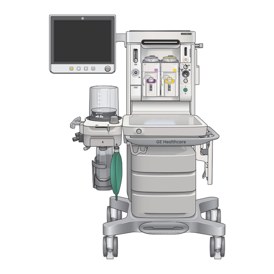
Page 6: Front View Components
Front view components 1. Anesthesia display 2. Auxiliary O flow control (optional) 3. Alt O flow control 4. Suction regulator and control (optional) 5. On/Standby switch 6. Vaporizer 7. Flip-up shelf (optional) 8. Drawers 9. Central brake 10. Caster brakes and cable sweeper 11. -
Page 7: Breathing System Components
Breathing system components 1. Bellows assembly 2. Adjustable pressure-limiting (APL) valve 3. Bag/Vent switch 4. Bag hose connection 5. Absorber canister 6. Absorber canister lifter handle 7. Leak test plug 8. Inspiratory port 9. Expiratory port 10. Breathing system guard 11. -
Page 8: Right Side View Components
Right side view components 1. Side rail 2. Pipeline connections 3. Right dovetail 4. Mains inlet and Mains power fuses 5. Outlet circuit breakers (optional) 220-240 V~ 50/60 Hz Class I... -
Page 9: Rear View Components
Rear view components 1. Display arm 2. Suction trap 3. Back cover (optional) RS 232... -
Page 10: Left Side View Components
Left side view components 1. Airway module (optional) and sample gas return port 2. Left dovetail 3. Anesthesia Gas Scavenging System (AGSS) connection Save Change Loop Loop Spirometry... -
Page 11: Central And Caster Brakes
Central and caster brakes The Carestation 750 system has one central brake with two brakes on the rear casters that hold the system in place. 1. Central brake: Push down on the central brake to lock the system in place. Lift up on the central brake to release the brake. -
Page 12: Using The Bag Support Arm
Using the bag support arm Use the optional bag support arm to hold the breathing circuit bag. The bag support arm can be moved up or down and left or right. Bag support arm... -
Page 13: Navigation
Navigation Display Controls 1. Touchscreen: Activates functions when touch areas on the screen are selected. 2. Audio Pause key: Stops audio for 120 seconds for any active, eligible high and medium priority alarms. Prevents audio (audio off) for 90 seconds when no medium or high priority alarms are active. 3. -
Page 14: Touch Points
Touch points 1. Wave fields 2. Measured values 3. Function keys 4. Digit fields 5. Ventilator quick keys 6. Gas quick keys 7. Split screen values... -
Page 15: Anesthesia System Display
Anesthesia system display 1. Audio pause symbol and countdown clock: Indicates when alarm audio is paused and the countdown clock until audio is on. 2. Alarm message fields: Displays the active alarms. 3. Waveform fields: Displays the waveforms of measured values. 4. General message fields or lock touchscreen indicator: Displays general messages and the touchscreen lock indicator. -
Page 16: Using Menus
Using menus 1. Menu: Displays the title of the open menu. For example: Start Case. 2. Menu items: The menu items will vary depending on the selected menu. 3. Instructions or help information: This shows any additional instructions or help messages. -
Page 17: Using The Comwheel
Using the ComWheel Use the ComWheel to scroll through the quick key settings and function keys, make selections, change settings, and confirm settings. Turn the ComWheel to the right: • For menu items, the highlight moves down • For quick keys, the highlight moves to the next key on the right •... -
Page 18: Using Quick Keys
Using quick keys The gas settings and the main ventilator settings for each ventilation mode can be changed using the quick keys. 1. Select a quick key to open the menu or select a parameter. 2. If O , Total Flow, Gas Setup, Mode or More Settings is selected, a menu displays. -
Page 19: Operation Overview
Operation overview Turning on the system Plug the power cord into an electrical outlet. 1. Make sure the mains indicator light is on. • The mains indicator is lit when AC power is connected • Battery is charging if it is not already fully charged 2. -
Page 20: Changing Gas Settings
Changing gas settings 1. Select the Gas Setup quick key. Gas Setup 2. For Other Gas, select the menu item and change using the Other Gas drop-down menu. 3. For O %, and Total Flow, select Total Flow the setting and make the change 6.00 l/min using the ComWheel and push to... -
Page 21: Using The Apl Valve
Using the APL valve The Adjustable Pressure-Limiting (APL) Valve adjusts the breathing system pressure limit during manual ventilation. Turn the APL valve clockwise to increase the pressure limit, turn the APL valve counterclockwise to decrease the pressure limit. Using the Bag/Vent switch The Bag/Vent Switch selects between manual ventilation (bag) and mechanical ventilation (ventilator). -
Page 22: Using The Vaporizer
Using the vaporizer Lock lever Concentration Use only Selectatec™ Series Vaporizers Tec™ 6 control and release Plus Vaporizer or greater. 1. Turn the lock lever full clockwise to lock the vaporizer in position. 2. Push the release and turn the concentration control to set the agent concentration. -
Page 23: Aux O +Air
Using Aux O +Air Use the optional Auxiliary O +Air (Aux O +Air) switch to deliver O Air through the Aux O +Air outlet on the front of the system. No anesthetic agent is delivered through the Aux +Air outlet. When the switch is set to the Aux O +Air position during a case, the outlet indicator is lit and N... -
Page 24: Checkout
Checkout Checkout overview The Checkout menu shows on the display after turning on the system. To access the Checkout menu between cases, select Checkout. Step-by-step instructions show in the Checkout menu during the tests. Use the Checkout menu to: • Perform a Full Test •... -
Page 25: Checkout Full Test
Checkout full test The full test runs automatically and beeps to indicate when it is finished or if interaction is required. Perform a Full Test when any component of the system is changed (breathing system, vaporizers, pipeline inlets). The Full Test does the following tests: Vent and Gas, Vaporizer Leak, and Circuit Leak. When one of the tests is completed, the next test begins. -
Page 26: Starting A Case
Starting a case Start Case menu overview Note: A super user is an authorized personnel who has been trained and qualified to change default settings. Use the Start Case menu to set the case data and start the case. A case can be started using default settings or using custom settings. -
Page 27: Starting A Case Using Default Settings
Starting a case using default settings Case Defaults contain five case type selections. Each case type has preset values for Ideal Weight, Age, and Volume Apnea Alarm. The first four default case types are configured and named by the Super User. The fifth default case is Last Case. -
Page 28: Starting A Case Using Custom Settings
Starting a case using custom settings Ideal Weight, Age, CO Alarms, and Volume Apnea Alarm can be custom set on the Start Case menu before starting a case. 1. Set the Bag/Vent switch to Bag. 2. Select Start Case. • The Case Defaults selection shows the first preset case type •... -
Page 29: Starting Manual Ventilation
Starting manual ventilation 1. Connect a manual breathing circuit. 2. Make sure the APL valve is set to a clinically appropriate value. 3. Set the Bag/Vent switch to Bag. Starting mechanical ventilation 1. Set the ACGO switch to the circle circuit position. -
Page 30: Changing A Ventilator Mode And Settings
Changing a ventilator mode and settings To change a vent mode: 1. Select the Mode quick key. The Vent Mode menu shows. 2. Select the desired ventilation mode. Set and confirm the primary ventilation setting to activate the ventilation mode. 3. -
Page 31: Alarms And Trends
Alarms and Trends Setting alarm limits To set an alarm limit: 1. Select Alarm Setup or... 2. Select one of the Measured Value fields. 3. From the Primary Limits and More Limits tabs, select the alarm limit and make the change. 4. -
Page 32: Additional Alarm Settings
Additional alarm settings The following alarms can be turned off to reduce nuisance alarms during manual ventilation if clinically appropriate: 1. CO Alarms: Use the CO Alarms setting to turn off the CO ‘Apnea’ alarm, EtCO low, EtCO high, and FiCO high and Absorbent OK? alarms during manual ventilation. -
Page 33: Setting Auto Limits
Setting Auto Limits Use the Auto Limits menu to quickly set alarm ranges for ‘MV’, ‘TV’, and ‘EtCO ’ during mechanical ventilation. 1. Select the Auto Limits key. The menu shows the current measured values and the proposed low and high alarm limits. -
Page 34: Ventilation Modes
Ventilation modes Volume control mode (VCV) • Supplies a set volume to the Tinsp patient Texp Insp • Calculates a flow based on the set Pause tidal volume and the length of the inspiratory time • Can compensate for breathing system compliance, fresh gas Peep flow, and moderate breathing... -
Page 35: Pcv-Vg Mode
PCV-VG mode • Tidal volume is set and volume is Tinsp Texp delivered using a decelerating Variable pressure to flow and constant pressure deliver desired TV • The ventilator will adjust the inspiratory pressure needed to deliver the set tidal volume Peep Time breath-by-breath so that the... -
Page 36: Simv Pcv Mode
SIMV PCV mode • Delivers a relatively slow breathing rate with pressure controlled breathing • Combines mandatory breaths with spontaneous breath support • If a trigger event occurs within the synchronized window, a new pressure-controlled breath is initiated • If a trigger event occurs elsewhere during the expiratory phase, a support for a spontaneous breath is provided with pressure support added as set by the clinician. -
Page 37: Simv Pcv-Vg Mode
SIMV PCV-VG mode • Delivers a set rate of pressure controlled breaths with a guaranteed volume • The ventilator will adjust the inspiratory pressure needed to deliver the set tidal volume breath-by-breath so that the lowest pressure is used. • The patient’s compliance is determined from the volume controlled ventilation breath and the inspiratory pressure level is then established for the next PCV-VG breath. -
Page 38: Psvpro™ Ventilation Mode
PSVPro™ Ventilation Mode • Pressure supported ventilation with apnea backup • Clinician sets the Psupport and PEEP levels, the patient establishes the rate, inspiratory flow and inspiratory time • Tidal volume is determined by the pressure, lung characteristics and patient effort •... -
Page 39: Special Features
Special features ecoFLOW overview The ecoFLOW option provides a split screen view that shows the approximate minimum O flow to maintain a Total Flow Agent preset FiO value. It also shows the approximate agent used per hour and the cost. The split screen shows the Paw gauge in the upper area €... -
Page 40: Ecoflow Menu Components
ecoFLOW menu components 1. Agent: Shows Agent cost and flow information. Total Flow Agent 2. Agent Cost: The cost of the current agent flow. This value is determined by the agent flow multiplied by the agent cost set by the Super User. 3. -
Page 41: Activating The Ecoflow Split Screen
Activating the ecoFLOW split screen 1. Select System Setup > Screen Setup. 2. Select the Layout tab. 3. Select Split Screen and select ecoFLOW from the drop-down menu. 4. Select Close. Recruitment Maneuver Use the Single Step recruitment maneuver to deliver a pressure breath for a set time during mechanical ventilation, without making multiple ventilator setting... -
Page 42: Pause Gas Flow
Pause Gas Flow Use Pause Gas Flow to temporarily suspend the flow of gas during a case. Using Pause Gas Flow while the breathing circuit is disconnected prevents the flow of gas into the room. Pause Gas Flow is available during both mechanical ventilation and manual ventilation. -
Page 43: Spirometry Overview
Spirometry overview Use the Spirometry menu to: • Set the loop type • Adjust the loop scaling • Save a loop to memory • Access the Setup Loops menu • View a saved loop • Delete a saved loop Note: If Spirometry is being displayed in a digit field, you can also access the Spirometry menu by... -
Page 44: Spirometry Loop Components
Spirometry loop components Spirometry loop components: 1. Volume axis 2. Pressure axis 3. Real-time loop (yellow) 4. Reference loop (grey) 5. There are three types of spirometry loops that can be selected from the Loop Type drop-down menu: Pressure-Volume (Paw-Vol), Flow-Volume (Flow-Vol), and Pressure-Flow (Paw-Flow). -
Page 45: Spirometry Setup
Spirometry setup Select Setup Loops from the Spirometry menu to access the Setup loops menu. 1. Spirometry Scaling: Set the scales of the spirometry loop graph. The available settings for the volume, Paw, and flow graph axis are dependent on the set patient type of adult or pediatric. -
Page 46: Cardiac Bypass
Cardiac Bypass There are two types of cardiac bypass. Manual ventilation cardiac bypass is standard. VCV cardiac bypass is optional. Manual ventilation cardiac bypass suspends alarms for patients on cardiac bypass when the ventilator is not mechanically ventilating. Systems with the VCV cardiac bypass option enabled can mechanically ventilate while in VCV mode. The VCV mode is the only ventilation mode available while using VCV cardiac bypass. -
Page 47: End Of Case And Standby
End of Case and Standby End Case Use the End Case menu to stop gas flow and end the patient alarms. The amount of gas used and agent used during the case shows in the menu. 1. Set the Bag/Vent switch to Bag. 2. -
Page 48: Standby
Standby When in Standby, most of the alarms are disabled. The Standby screen shows after End Case is selected. From the Standby menu: 1. Select System Setup to open the System Setup menu. 2. Select Checkout to open the Checkout menu. 3. -
Page 49: Turning Off The System
Turning off the system 1. Perform the End a case procedure, if appropriate. 2. Push and hold the On/Standby switch for 1 second. 3. Select Confirm or push the ComWheel within 10 seconds to turn off the system. If no action is performed within 10 seconds, the screen automatically returns to the previous display. - Page 50 GE Healthcare provides transformational medical technologies and services that are shaping a new age of patient care. Our broad expertise in medical imaging and information technologies, medical diagnostics, patient monitoring systems, drug discovery, biopharmaceutical manufacturing technologies, performance improvement and performance solutions services help our customers to deliver better care to more people around the world at a lower cost.
Need help?
Do you have a question about the Carestation 750 and is the answer not in the manual?
Questions and answers
What is the intended purpose of the ‘alt O2’ ? Page 6 of manual, front view component number 3