GE 750 Instruction Manual
Hide thumbs
Also See for 750:
- Instruction manual (504 pages) ,
- Manual (102 pages) ,
- Quick reference manual (58 pages)
Table of Contents
Advertisement
Quick Links
GE
Digital Energy
GE Digital Energy
650 Markland Street
Markham, Ontario
Canada L6C 0M1
Tel: +1 905 927 7070 Fax: +1 905 927 5098
Internet:
http://www.gedigitalenergy.com
*1601-0120-AG*
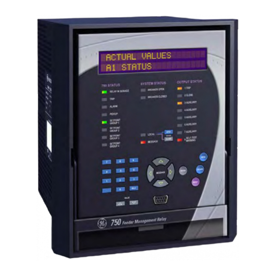
750/760 Feeder Management
Software Revision: 7.4x
Manual P/N: 1601-0120-AG
Manual Order Code: GEK-106471Q
Instruction Manual
Relay
GE Digital Energy's Quality
Management System is
registered to ISO9001:2008
QMI # 005094
Advertisement
Table of Contents

Related Manuals for GE 750


Summary of Contents for GE 750
- Page 1 Digital Energy 750/760 Feeder Management Relay Instruction Manual GE Digital Energy 650 Markland Street Software Revision: 7.4x Markham, Ontario Manual P/N: 1601-0120-AG Manual Order Code: GEK-106471Q Canada L6C 0M1 Tel: +1 905 927 7070 Fax: +1 905 927 5098 Internet: http://www.gedigitalenergy.com...
- Page 2 The contents of this manual are the property of GE Multilin Inc. This documentation is furnished on license and may not be reproduced in whole or in part without the permission of GE Multilin. The content of this manual is for informational use only and is subject to change without notice.
- Page 3 Indicates a hazardous situation which, if not avoided, could result in minor or Note moderate injury. Indicates practices not related to personal injury. Note Indicates general information and practices, including operational information and practices, that are not related to personal injury. NOTE 750 FEEDER MANAGEMENT RELAY – INSTRUCTION MANUAL...
- Page 4 CHAPTER 1: 750 FEEDER MANAGEMENT RELAY – INSTRUCTION MANUAL...
-
Page 5: Table Of Contents
...................... 2-14 ROTECTION LEMENTS ....................2-17 ONITORING LEMENTS ......................2-18 ONTROL LEMENTS ..........................2-20 UTPUTS ........................2-20 UTPUT ELAYS CPU ............................2-20 ..........................2-21 HYSICAL ..........................2-22 ESTING ........................... 2-23 PPROVALS 750 FEEDER MANAGEMENT RELAY – INSTRUCTION MANUAL TOC - I... - Page 6 ENERVISTA 750/760 SETUP SOFTWARE INTERFACE ............4-13 ..........................4-13 VERVIEW ........................... 4-13 ARDWARE 750/760 S .......... 4-15 NSTALLING THE ISTA ETUP OFTWARE CONNECTING ENERVISTA 750/760 SETUP TO THE RELAY ..........4-18 ............... 4-18 ONFIGURING ERIAL OMMUNICATIONS ................4-20 SING THE UICK ONNECT EATURE ..............4-20...
-
Page 7: Trip Relay
........................4-37 OGGER ....................... 4-37 VENT ECORDER ......................4-38 ODBUS ....................4-39 IEWING CTUAL ALUES USING ENERVISTA VIEWPOINT WITH THE 750/760 ............4-41 ....................4-41 LUG AND XAMPLE 5: SETPOINTS OVERVIEW ............................5-1 ..................... 5-1 ETPOINTS ....................5-5 ETPOINT NTRY ETHODS ..................... -
Page 8: A1 Status
........................... 6-8 LOCK (760 ) ....................6-8 UTORECLOSE ONLY A2 METERING ............................. 6-10 ....................6-10 ETERING ONVENTIONS ..........................6-11 URRENT ..........................6-12 OLTAGE .......................... 6-13 REQUENCY ....................6-14 YNCHRONIZING OLTAGE TOC - IV 750 FEEDER MANAGEMENT RELAY – INSTRUCTION MANUAL... - Page 9 ONITORING ........................7-56 NALOG NPUTS ..................7-57 VERFREQUENCY ONITORING ........................7-58 OWER ACTOR VT F .......................... 7-58 AILURE ......................7-59 ONITOR ......................7-60 LOSE ONITOR ..................7-60 REAKER PERATION AILURE 750 FEEDER MANAGEMENT RELAY – INSTRUCTION MANUAL TOC - V...
- Page 10 EU D ................. 8-3 ECLARATION OF ONFORMITY REVISION HISTORY .......................... 8-4 ........................8-4 ELEASE ATES ........................8-4 ELEASE OTES GE MULTILIN DEVICE WARRANTY ..................... 8-8 ..................... 8-8 ARRANTY TATEMENT I: INDEX TOC - VI 750 FEEDER MANAGEMENT RELAY – INSTRUCTION MANUAL...
-
Page 11: Important Procedures
Ensure that the following items are included: • Instruction Manual • GE EnerVista CD (includes software and relay documentation) • Mounting screws. For product information, instruction manual updates, and the latest software updates, please visit the GE Multilin website at http://www.gedigitalenergy.com. - Page 12 2–11. The remainder of this manual should be read and kept for reference to ensure maximum benefit from the 750 and 760. For further information, please consult your local sales representative or the factory. Comments about new features or modifications for your specific requirements are welcome and encouraged.
-
Page 13: Using The Relay
The setpoint pages are numbered, have an ‘S’ prefix for easy identification, and have a name which provides a general idea of the settings available in that page. 750 FEEDER MANAGEMENT RELAY – INSTRUCTION MANUAL 1 - 3... -
Page 14: A2 Metering
Press the key until the sub-page heading DEMAND MESSAGE appears. At this point, press the key to display the MESSAGE messages in this sub-page. DEMAND [] 1 - 4 750 FEEDER MANAGEMENT RELAY – INSTRUCTION MANUAL... - Page 15 MAX PHASE A CURRENT DEMAND: Press the key to reverse the process described above MESSAGE and return the display to the previous level. PHASE A [] CURRENT 750 FEEDER MANAGEMENT RELAY – INSTRUCTION MANUAL 1 - 5...
-
Page 16: Actual Values
ACTUAL VALUES [] TRIP COUNTER [] MESSAGE A3 MAINTENANCE ARCING CURRENT [] TOTAL ARCING CURRENT MESSAGE MESSAGE φ - cycle TOTAL ARCING CURRENT MESSAGE φ - cycle 1 - 6 750 FEEDER MANAGEMENT RELAY – INSTRUCTION MANUAL... -
Page 17: Changing Setpoints
A complete editable setpoint chart is available as an Excel spreadsheet from the GE Multilin website at http://www.gedigitalenergy.com. All of the 750/760 settings fall into one of following categories: device settings, system settings, logic input settings, output relay settings, monitoring settings, control settings, and testing settings. -
Page 18: The Help Key
The first method uses the 750/760 numeric keypad in the same way as any electronic calculator. A number is entered one digit at a time with the 0 to 9 and decimal keys. The left-most digit is entered first and the right-most digit is entered last. - Page 19 VT Ratio: 14400 / 115 = 125.2 To set the phase CT primary rating, modify the S2 SYSTEM SETUP CURRENT SENSING setpoint as shown below. PHASE CT PRIMARY 750 FEEDER MANAGEMENT RELAY – INSTRUCTION MANUAL 1 - 9...
- Page 20 ENTER NEW SETPOINT STORED To set the ground bus VT connection type, modify the S2 SYSTEM SETUP BUS VT SENSING setpoint as shown below. VT CONNECTION TYPE 1 - 10 750 FEEDER MANAGEMENT RELAY – INSTRUCTION MANUAL...
- Page 21 ENTER NEW SETPOINT STORED To set the VT ratio, modify the setpoint S2 SYSTEM SETUP BUS VT SENSING VT RATIO as shown below. 750 FEEDER MANAGEMENT RELAY – INSTRUCTION MANUAL 1 - 11...
- Page 22 For the previous example, pressing the HELP HELP during setpoint entry displays the corresponding minimum, maximum and step values for the displayed setpoint, as well as contact information if further assistance is required. 1 - 12 750 FEEDER MANAGEMENT RELAY – INSTRUCTION MANUAL...
-
Page 23: Etpoints
PHASE TIME O/C 1 RELAYS (3-7): 3---- Press the key to store this change into memory. As before, ENTER confirmation of this action will momentarily flash on the display. NEW SETPOINT STORED 750 FEEDER MANAGEMENT RELAY – INSTRUCTION MANUAL 1 - 13... - Page 24 Once a character is entered by pressing key, it is automatically saved in flash memory as a new ENTER setpoint. USER INPUT A NAME: Substation Monitor 1 - 14 750 FEEDER MANAGEMENT RELAY – INSTRUCTION MANUAL...
-
Page 25: Application Example
Define if the output relays will be set as fail-safe type. • Define if the 750/760 will be used to close the breaker. If that will be the case, gather information on the conditions that will be used to verify synchronism. - Page 26 It also assumes that relay setpoints are unaltered from their factory default values. Refer to the following figures for schematics related to this application example. 1 - 16 750 FEEDER MANAGEMENT RELAY – INSTRUCTION MANUAL...
- Page 27 CHAPTER 1: GETTING STARTED APPLICATION EXAMPLE FIGURE 1–1: Typical Three-Line Diagram 750 FEEDER MANAGEMENT RELAY – INSTRUCTION MANUAL 1 - 17...
- Page 28 APPLICATION EXAMPLE CHAPTER 1: GETTING STARTED RS485 SERIAL NETWORK FIGURE 1–2: Typical Connection Diagram 1 - 18 750 FEEDER MANAGEMENT RELAY – INSTRUCTION MANUAL...
- Page 29 CHAPTER 1: GETTING STARTED APPLICATION EXAMPLE FIGURE 1–3: Typical Control Diagram 750 FEEDER MANAGEMENT RELAY – INSTRUCTION MANUAL 1 - 19...
- Page 30 APPLICATION EXAMPLE CHAPTER 1: GETTING STARTED FIGURE 1–4: Typical Breaker Control Diagram 1 - 20 750 FEEDER MANAGEMENT RELAY – INSTRUCTION MANUAL...
- Page 31 CHAPTER 1: GETTING STARTED APPLICATION EXAMPLE FIGURE 1–5: Typical Relay Control Diagram 750 FEEDER MANAGEMENT RELAY – INSTRUCTION MANUAL 1 - 21...
- Page 32 RTU. Please note that, similar information could be exchanged between the RTU and the relay via an RS485 or RS422 serial link using Modbus RTU protocol. Refer to GE Publication GEK-106473: 750/760 Communications Guide for additional information.
- Page 33 For additional information refer to Current SENSTV GND CT Sensing on page 5–22. For voltage transformers, make the following changes in the S2 SYSTEM SETUP BUS VT setpoints page: SENSING 750 FEEDER MANAGEMENT RELAY – INSTRUCTION MANUAL 1 - 23...
- Page 34 For additional information, refer to Bus VT Sensing on page 5–22. The 750/760 was designed to display primary system values. Current and voltage measurements are performed at secondary levels, which the relay transforms to primary values using CT and VT ratios, as well as nominal secondary values.
- Page 35 To setup an Alarm-after-Delay input, make the following changes to the S3 LOGIC INPUTS setpoints page. Press the key after each setpoint is USER INPUT A MESSAGE completed to move to the next message. 750 FEEDER MANAGEMENT RELAY – INSTRUCTION MANUAL 1 - 25...
- Page 36 For the Neutral Instantaneous Overcurrent 1 element, enter the following values in the setpoints page. PROTECTION NEUTRAL CURRENT NEUTRAL INST OVERCURRENT 1 Press the key after each setpoint is completed to move to the next message. MESSAGE 1 - 26 750 FEEDER MANAGEMENT RELAY – INSTRUCTION MANUAL...
-
Page 37: I Nstallation
Ready state. Note that the relay is defaulted to the Not Ready state when it leaves the factory. A minor self-test warning message informs the user that the 750/760 has not yet been programmed. If this warning is ignored, protection is active and will be using factory default setpoints. -
Page 38: Commissioning
Extensive commissioning tests are available in Chapter : Commissioning. Commissioning tables for recording required settings are available in Microsoft Excel format from the GE Multilin website at http://www.gedigitalenergy.com. The website also contains additional technical papers and FAQs relevant to the 750/760 Feeder Management Relay. 1 - 28... -
Page 39: Overview
To simplify programming and provide a more intuitive interface, setpoints can be entered with a PC running the EnerVista 750/760 Setup software provided with the relay. Even with minimal computer knowledge, this menu-driven software provides easy access to all front panel functions. - Page 40 Chapter 5: Setpoints. The logic diagrams include a reference to every setpoint related to a feature and show all logic signals passed between individual features. Information related to the selection of settings for each setpoint is also provided. 2 - 2 750 FEEDER MANAGEMENT RELAY – INSTRUCTION MANUAL...
-
Page 41: Analog Input
Trip/Close Circuit Failure Total Breaker Arcing Current VT Failure Demand (A, MW, Mvar, MVA) Analog Input Event Recording Analog Output Fault Locator Trip Counter 826712A1.CDR FIGURE 2–1: Summary of Features 750 FEEDER MANAGEMENT RELAY – INSTRUCTION MANUAL 2 - 3... - Page 42 OPERATING CURRENT 50SG 67SG 51SG Control 818840AD.dwg * POLARIZING CURRENT AND GND CURRENT ARE MUTUALLY EXCLUSIVE SINCE BOTH USE THE SAME RELAY CT INPUT TERMINALS FIGURE 2–2: Functional Block Diagram 2 - 4 750 FEEDER MANAGEMENT RELAY – INSTRUCTION MANUAL...
-
Page 43: Theory Of Operation
Also, sampling is synchronized to the Va-x voltage zero crossing which results in better co-ordination for multiple 750/760 relays on the same bus. If a stable frequency signal is not available then the sampling rate defaults to the nominal system frequency. - Page 44 – of the SR750 relay. The response time depends on the ratio between the fault current and the applied setting and varies from 16ms for high multiples of pickup to 25ms for multiple of 1.2 times pickup. 2 - 6 750 FEEDER MANAGEMENT RELAY – INSTRUCTION MANUAL...
- Page 45 Contact inputs are de-bounced to eliminate false operations due to noise. The inputs must be in the same state for three consecutive readings spaced evenly over one power frequency cycle before a new state is recognized. 750 FEEDER MANAGEMENT RELAY – INSTRUCTION MANUAL 2 - 7...
- Page 46 THEORY OF OPERATION CHAPTER 2: INTRODUCTION FIGURE 2–3: Hardware Block Diagram 2 - 8 750 FEEDER MANAGEMENT RELAY – INSTRUCTION MANUAL...
-
Page 47: Ordering
Conformal Coating 2.3.2 Example Order Codes The 750-P1-G1-S1-LO-A10-R-B specifies a 750 Feeder Management Relay with 1 A phase, zero-sequence, and sensitive ground current Inputs, low control power, eight 0 to 10 mA analog outputs, a red LED for the Breaker Closed indicator, and a basic display. -
Page 48: A Ccessories
• SR19-1 or SR19-2 PANEL: Single or double cutout 19-inch panels • RS-232/485: RS232 to RS485 converter box for harsh industrial environments • 1 A and 5 A PHASE CTs: 50, 75, 100, 150, 200, 250, 300, 350, 400, 500, 600, 750, and 1000 CT ratios •... -
Page 49: Specifications
0.025 VA 1 A Phase & 0.60 VA 0.02 Ground 20 A 10 VA 0.40 VA 5 A Phase & 25 A 10 VA 0.02 Ground 100 A 120 VA 750 FEEDER MANAGEMENT RELAY – INSTRUCTION MANUAL 2 - 11... - Page 50 The harmonic components of current and voltage are removed from the input voltage and current parameters, so all relay measurements based on these quantities respond to the fundamental component only. To minimize errors, the A/D process utilizes a sampling rate 2 - 12 750 FEEDER MANAGEMENT RELAY – INSTRUCTION MANUAL...
-
Page 51: Current
Thermal exponential, 90% response time (programmed): 5, 10, 15, 20, 30, or 60 min. Block interval / rolling demand, time interval (programmed): 5, 10, 15, 20, 30, or 60 min. 750 FEEDER MANAGEMENT RELAY – INSTRUCTION MANUAL 2 - 13... - Page 52 97 to 98% of pickup level, or pickup level minus 2% of nominal current (0.02 x CT), whichever is less Time delay: 0 to 600.00 s in steps of 0.01 2 - 14 750 FEEDER MANAGEMENT RELAY – INSTRUCTION MANUAL...
- Page 53 0 to 1.25 × VT in steps of 0.01 Dropout level: 102 to 103% of pickup Curve: Definite Time or Inverse Time Time delay: 0 to 6000.0 s in steps of 0.1 750 FEEDER MANAGEMENT RELAY – INSTRUCTION MANUAL 2 - 15...
- Page 54 100 ms Level accuracy: see 3Φ Real Power metering Time delay: 0.0 to 6000.0 s in steps of 0.1 Timing accuracy: ±200 ms (includes Reverse Power pickup time) 2 - 16 750 FEEDER MANAGEMENT RELAY – INSTRUCTION MANUAL...
- Page 55 Storage: 2 to 16 events with 2048 to 256 samples of data respectively (4096 if continuous) TRIP COUNTERS Accumulates all ground, sensitive ground, neutral, negative sequence, and phase overcurrent trips. 750 FEEDER MANAGEMENT RELAY – INSTRUCTION MANUAL 2 - 17...
- Page 56 SYNCHROCHECK Voltage difference: 0.01 to 100.00 kV in steps of 0.01 Phase difference: 0 to 100° in steps of 1 Frequency difference: 0.00 to 5.00 Hz in steps of 0.01 2 - 18 750 FEEDER MANAGEMENT RELAY – INSTRUCTION MANUAL...
- Page 57 Up to four (4) before lockout. Blocking: Each reclose shot can block IOC and raise TOC Pickup. Adjustability: Current supervision can adjust the maximum number of shots to be attempted. 750 FEEDER MANAGEMENT RELAY – INSTRUCTION MANUAL 2 - 19...
- Page 58 15 A at 250 V DC for 500 ms 2.4.8 Output Relays Relay contacts must be considered unsafe to touch when the 750/760 is energized! If the output relay contacts are required for low voltage accessible applications, it is the customer’s responsibility to ensure proper insulation levels.
-
Page 59: P Hysical
Fully drawout unit (automatic CT shorts) Approvals: Meets CE drawout specifications Seal: Seal provision Door: Dust tight door Mounting: Panel or 19" rack mount Weight: 7.9 kg (case and relay) 9.4 kg (shipping weight) 750 FEEDER MANAGEMENT RELAY – INSTRUCTION MANUAL 2 - 21... -
Page 60: T Esting
SPECIFICATIONS CHAPTER 2: INTRODUCTION 2.4.11 Testing TYPE TESTING The table below lists the 750/760 type tests: Standard Test Name Level EIA 485 RS485 Communications Test 32 units at 4000 ft. IEC 60068-2-30 Relative Humidity Cyclic 55°C at 95% RH IEC 60068-2-38 Composite Temperature/Humidity 65/–10°C at 93% RH... -
Page 61: A Pprovals
Part 15; RF Emissions for North America IEC: IEC 1010-1 LVD - CE for Europe ISO: GE Multilin’s Quality Management System is registered to ISO9001:2000 QMI # 005094 UL #A3775 UL listed for the USA and Canada, E83849 Specifications subject to change without notice. - Page 62 SPECIFICATIONS CHAPTER 2: INTRODUCTION 2 - 24 750 FEEDER MANAGEMENT RELAY – INSTRUCTION MANUAL...
- Page 63 3.1.1 Drawout Case The 750/760 is packaged in the standard SR series arrangement which consists of a drawout relay and a companion case. The case provides mechanical protection for the drawout portion and is used to make permanent electrical connections to external equipment.
- Page 64 3.1.2 Installation The 750/760 can be mounted alone or adjacent to another SR-series unit on a standard 19-inch rack panel. Panel cutout dimensions for both conditions shown below. When planning the location of your panel cutout, ensure provision is made for the front door to swing open without interference to or from adjacent equipment.
-
Page 65: Mechanical Installation
To remove the unit from the case: Open the door by pulling from the top or bottom of its right side. It will rotate to the left about its hinges. 750 FEEDER MANAGEMENT RELAY – INSTRUCTION MANUAL 3 - 3... -
Page 66: I Nstallation
Re-insert the relay into its draw-out case, and engage the handle. Arrange to remove the draw-out from the switchgear by removing the wiring from the terminals. Contact the GE Digital Energy Technical Support team for any additional assistance. - Page 67 When the “stop” position is reached, the locking mechanism will release. The relay will now slide out of the case when pulled using its handle. To free the relay, it may sometimes be necessary to slightly adjust the handle position. 750 FEEDER MANAGEMENT RELAY – INSTRUCTION MANUAL 3 - 5...
- Page 68 No special ventilation requirements need to be observed during the installation of the unit. Note The unit does not require cleaning. NOTE 3 - 6 750 FEEDER MANAGEMENT RELAY – INSTRUCTION MANUAL...
-
Page 69: E Thernet C Onnection
FIGURE 3–5: Ethernet Cable Connection 3.1.5 Rear Terminal A broad range of applications are available for the 750/760 relays. As such, it is not Layout possible to present typical connections for all possible schemes. The information in this section will cover the important aspects of interconnections, in the general areas of instrument transformer inputs, other inputs, outputs, communications and grounding. -
Page 70: Inputs/Outputs
ANALOG OUTPUT 2 + 4 AUXILIARY RELAY NC ANALOG OUTPUT 3 + 5 AUXILIARY RELAY NC ANALOG OUTPUT 4 + 5 AUXILIARY RELAY NO ANALOG OUTPUT 5 + 6 AUXILIARY RELAY NC 3 - 8 750 FEEDER MANAGEMENT RELAY – INSTRUCTION MANUAL... - Page 71 PHASE VT NEUTRAL (BUS) LOGIC INPUT 14 PHASE A CT RESERVED PHASE B CT RESERVED PHASE C CT RESERVED GROUND CT RESERVED CONTROL POWER – DC NEGATIVE CONTROL POWER + 750 FEEDER MANAGEMENT RELAY – INSTRUCTION MANUAL 3 - 9...
-
Page 72: Electrical Installation
ELECTRICAL INSTALLATION CHAPTER 3: INSTALLATION Electrical Installation FIGURE 3–8: Typical Wiring Diagram 3 - 10 750 FEEDER MANAGEMENT RELAY – INSTRUCTION MANUAL... -
Page 73: C Urrent I Nputs
3.2.2 Current Inputs The 750/760 relays have five (5) channels for AC current inputs, each with an isolating transformer and an automatic shorting mechanism that acts when the relay is withdrawn from its case. There are no internal ground connections on the current inputs. Current transformers with 1 to 50000 A primaries may be used. - Page 74 Restricted Earth Fault protection is often applied to transformers having grounded wye Earth Fault windings to provide sensitive ground fault detection for faults near the transformer neutral. The Sensitive Ground input (Terminals G3 and H3) can be used. Inputs 3 - 12 750 FEEDER MANAGEMENT RELAY – INSTRUCTION MANUAL...
-
Page 75: Input
Although the 750/760 is designed for feeder protection, it can provide Restricted Earth Note Fault protection on transformers that do not have dedicated protection. To use the 750/ 760 for this type of protection, a stabilizing resistor and possibly a non-linear resistor will NOTE be required. - Page 76 A tinned copper, braided, shielding and bonding cable should be used. As a minimum, 96 strands of number 34 AWG should be used. Belden catalog number 8660 is suitable. 3 - 14 750 FEEDER MANAGEMENT RELAY – INSTRUCTION MANUAL...
-
Page 77: Control Power
52a auxiliary contact is also open and no trickle current will flow. When the breaker position monitoring inputs detect an open breaker, the trip coil supervision monitoring function will be disabled. 750 FEEDER MANAGEMENT RELAY – INSTRUCTION MANUAL 3 - 15... - Page 78 52a/b contact. A high speed solid state (SCR) output is also provided. This output is intended for applications where it is required to key a communications channel. 3 - 16 750 FEEDER MANAGEMENT RELAY – INSTRUCTION MANUAL...
-
Page 79: Analog Input
Ensure the maximum burden limits are not exceeded as per relay specifications, and avoid locating wire in close proximity to NOTE current carrying cables, contactors or other sources of high EMI. 750 FEEDER MANAGEMENT RELAY – INSTRUCTION MANUAL 3 - 17... -
Page 80: A Nalog O Utputs
ELECTRICAL INSTALLATION CHAPTER 3: INSTALLATION The 750/760 relays provide eight (8) analog output channels whose full scale range was specified at the time of ordering. Refer to Outputs on page 2–20 for the specifications and Ordering on page 2–9 for the complete listing. - Page 81 To ensure maximum reliability, all equipment should have similar transient protection devices installed. FIGURE 3–18: RS485 Wiring Diagram 750 FEEDER MANAGEMENT RELAY – INSTRUCTION MANUAL 3 - 19...
- Page 82 The 9-pin RS232 serial port located on the front panel is used in conjunction with the EnerVista 750/760 Setup software for programming setpoints and upgrading relay firmware. A standard 9-pin RS232 cable is used to connect the relay to a personal computer as shown below.
-
Page 83: Irig-B
IRIG-B SR FAMILY RG58/59 COAXIAL CABLE TIME CODE GENERATOR IRIG-B(+) RECEIVER (DC SHIFT OR – AMPLITUDE MODULATED IRIG-B(-) SIGNAL CAN BE USED) 818838A7.CDR TO OTHER DEVICES FIGURE 3–21: IRIG-B Connection 750 FEEDER MANAGEMENT RELAY – INSTRUCTION MANUAL 3 - 21... - Page 84 ELECTRICAL INSTALLATION CHAPTER 3: INSTALLATION 3 - 22 750 FEEDER MANAGEMENT RELAY – INSTRUCTION MANUAL...
-
Page 85: Front Panel Interface
The control keys are used to select the appropriate message for entering setpoints or displaying measured values. The RS232 program port is also provided for connection with a computer running the EnerVista 750/760 Setup software. 4.1.2... -
Page 86: Led Indicators
4.2.1 Description The front panel indicators are grouped into three columns. The 750/760 Status column indicates the state of the relay; the System Status column indicates the state of the breaker and the system; and the Output Status column indicates the state of the output relays. - Page 87 RECLOSURE ENABLED (760 only): This indicator will be on continuously when autoreclosure is allowed to operate as programmed. This is when the autoreclose function setpoint is enabled, and if used, the block reclosure logic input is not asserted. 750 FEEDER MANAGEMENT RELAY – INSTRUCTION MANUAL 4 - 3...
- Page 88 4.2.4 Output Status The 750/760 has eight (8) output relays: the 1 Trip, 2 Close, and 8 Self-Test Warning relays LED Indicators have fixed operation while the 3 to 7 Auxiliary relays are configurable. Regardless of the mode of operation, the corresponding front panel indicator turns on while the output relay is signaling.
- Page 89 Warning Relay signals loss of protection by de-energizing, but the LED indicator remains off. Since there are no shorting contacts across the Self-Test Warning Relay, both the normally open and normally closed contacts are open when the unit is drawn out. 750 FEEDER MANAGEMENT RELAY – INSTRUCTION MANUAL 4 - 5...
-
Page 90: Relay Messages
RELAY MESSAGES CHAPTER 4: INTERFACES Relay Messages 4.3.1 Keypad The 750/760 display messages are organized into Main Menus, Pages, and Sub-pages. Operation There are three main menus labeled Setpoints, Actual Values, and Target Messages. Pressing the key followed by the key scrolls through the three Main ... -
Page 91: D Iagnostic M Essages
(EEPROM). Maintenance alerts indicate excessive use. "Event Rate HIgh": This alert usually indicates that communication with a programmable logic controller or SCADA is continually recording events in the 750 event recorder. Programmable controller should be revised or 750 setpoints adjusted to reduce event recording. - Page 92 Any function of the relay is susceptible to malfunction from this failure. Contact Multilin Technical Support. Force Analog Out Minor Occurs when the setpoint is “Enabled”. FORCE A/O FUNCTION 4 - 8 750 FEEDER MANAGEMENT RELAY – INSTRUCTION MANUAL...
- Page 93 This warning occurs when microprocessor self-monitoring Self-Test 2 Major detects task execution failure. This warning occurs when Enervista 750 Setup software Test Mode 3 Major sends Modbus command to SR750 for firmware update from version 7.40 to a following version.
-
Page 94: F Lash M Essages
The edited VALUE NOT STORED value was either less than the minimum or greater than the maximum acceptable values for the edited setpoint and as a result was not stored. 4 - 10 750 FEEDER MANAGEMENT RELAY – INSTRUCTION MANUAL... - Page 95 IS NOW RESTRICTED S1 RELAY SETUP setpoint. The PASSCODE RESTRICT ACCESS TO SETPOINTS command to restrict access to setpoints has been successfully executed and setpoints cannot be changed. 750 FEEDER MANAGEMENT RELAY – INSTRUCTION MANUAL 4 - 11...
- Page 96 It can be used while disconnected (i.e. off-line) or connected (i.e. on-line) to a 750/760 device. In off-line mode, settings files can be created for eventual downloading to the device. In on-line mode, you can communicate with the device in real- time.
-
Page 97: Enervista 750/760 Setup Software Interface
CHAPTER 4: INTERFACES ENERVISTA 750/760 SETUP SOFTWARE INTERFACE FIGURE 4–3: Communications using the Front RS232 Port FIGURE 4–4: Communications using Rear RS485 Port 750 FEEDER MANAGEMENT RELAY – INSTRUCTION MANUAL 4 - 13... - Page 98 NOTE 996711A1.CDR FIGURE 4–5: Communications using Rear Ethernet Port 4.4.3 Installing the The following minimum requirements must be met for the EnerVista 750/760 Setup EnerVista 750/ software to operate on your computer. 760 Setup • Pentium class or higher processor (Pentium II 300 MHz or better recommended) Software •...
- Page 99 Check Now button to list software items for the 750/760. 6. Select the EnerVista 750/760 Setup software and release notes (if desired) from the list and click the Download Now button to obtain the installation pro- gram.
- Page 100 EnerVista 750/760 Setup software to the Windows start menu. 11. Click Finish to end the installation. The 750/760 device will be added to the list of installed IEDs in the EnerVista Launchpad window, as shown below.
- Page 101 In this example, we will use “Substation 1” as the site name. Click the OK button when complete. 4. The new site will appear in the upper-left list in the EnerVista 750/760 Setup window. 5. Click the Add Device button to define the new device.
-
Page 102: Connecting Enervista 750/760 Setup To The Relay
Using the The Quick Connect button can be used to establish a fast connection through the front Quick Connect panel RS232 port of a 750/760 relay. The following window will appear when the Quick Connect button is pressed: Feature As indicated by the window, the Quick Connect feature quickly connects the EnerVista 750/ 760 Setup software to a 750/760 front port with the following settings: 9600 baud, no parity, 8 bits, 1 stop bit. - Page 103 CHAPTER 4: INTERFACES CONNECTING ENERVISTA 750/760 SETUP TO THE RELAY The 750/760 Site Device has now been configured via the Quick Connect feature for serial communications. Proceed to Connecting to the Relay on page 4–20 to begin communications. 4.5.3 Configuring...
- Page 104 CONNECTING ENERVISTA 750/760 SETUP TO THE RELAY CHAPTER 4: INTERFACES 8. Click the Read Order Code button to connect to the 750/760 and upload the order code. If an communications error occurs, ensure that the Ethernet com- munications values correspond to the relay setting values.
- Page 105 Other setpoint and commands windows can be displayed and edited in a similar manner. Actual values windows are also available for display. These windows can be locked, arranged, and resized at will. Refer to the EnerVista 750/760 Setup Help File for additional information about the Note using the software.
- Page 106 Working with Setpoints and Setpoint Files 4.6.1 Engaging a The EnerVista 750/760 Setup software may be used in on-line mode (relay connected) to Device directly communicate with a 750/760 relay. Communicating relays are organized and grouped by communication interfaces and into sites. Sites may contain any number of relays selected from the SR or UR product series.
-
Page 107: O Verview
Opening any EnerVista 750/760 Setup file will automatically launch the application or provide focus to the already opened application. If the file is a settings file (has a ‘750’ or ‘760’ extension) which had been removed from the Settings List tree menu, it will be added back to the Settings List tree. -
Page 108: Working With Setpoints And Setpoint Files
Testing Factory default values are supplied and can be restored after any changes. The EnerVista 750/760 Setup display relay setpoints with the same hierarchy as the front panel display. For specific details on setpoints, refer to Chapter 5. Downloading and Saving Setpoints Files Setpoints must be saved to a file on the local PC before performing any firmware upgrades. -
Page 109: H Ardware
Open. The new file and complete path will be added to the file list. Creating a New Setpoint File The EnerVista 750/760 Setup software allows the user to create new setpoint files independent of a connected device. These can be uploaded to a relay at a later date. The following procedure illustrates how to create new setpoint files. - Page 110 Name box. Select the file name and path to store the file, or select any displayed file name to update an existing file. All 750/760 setpoint files should have the extension ‘750’ or ‘760’ (for example, ‘feeder1.750’). Click Save and OK to complete the process. Once this step is completed, the new file, with a complete path, will be added to the EnerVista 750/760 Setup software environment.
- Page 111 WORKING WITH SETPOINTS AND SETPOINT FILES Printing Setpoints and Actual Values The EnerVista 750/760 Setup software allows the user to print partial or complete lists of setpoints and actual values. Use the following procedure to print a list of setpoints: Select a previously saved setpoints file in the File pane or establish communications with a 750/760 device.
- Page 112 WORKING WITH SETPOINTS AND SETPOINT FILES CHAPTER 4: INTERFACES Select the previously saved setpoints file from the File pane of the EnerVista 750/760 Setup software main window. Select the File > Properties menu item and verify that the corresponding file is fully compatible with the hardware and firmware version of the target relay.
- Page 113 Technical Support team for more details. 4.7.2 Saving Before upgrading firmware, it is very important to save the current 750/760 settings to a Setpoints To A file on your PC. After the firmware has been upgraded, it will be necessary to load this file back into the 750/760.
- Page 114 EnerVista 750/760 Setup software now prepares the 750/760 to receive the new firmware file. The 750/760 front panel will momentarily display “Code Programming Mode Ready,” indicating that it is in upload mode. The 750/760 front panel continues with display “Erasing Analog Board Flash Memory.”...
-
Page 115: Upgrading Relay Firmware
CHAPTER 4: INTERFACES UPGRADING RELAY FIRMWARE While the file is being loaded into the 750/760, a status box appears showing how much of the new firmware file has been transferred and how much is remaining, as well as the upgrade status. The entire transfer process takes approximately 15 minutes if communicating at 19200 baud.. - Page 116 The EnerVista 750/760 Setup software can be used to capture waveforms (or view trace Capture (Trace memory) from the 750/760 relay at the instance of a trip. A maximum of 512 cycles can be captured and the trigger point can be adjusted to anywhere within the set cycles. A Memory) maximum of 16 waveforms can be buffered (stored) with the buffer/cycle trade-off.
- Page 117 Then, find the event that matches the same time and date in the event recorder. The event record will provide additional information on the cause and the system conditions at the time of the event. Additional information on 750 FEEDER MANAGEMENT RELAY – INSTRUCTION MANUAL 4 - 33...
-
Page 118: Advanced Enervista 750/760 Setup Features
Click OK to store these graph attributes, and to close the window. 10. The Waveform Capture window will reappear with the selected graph attributes available for use. 4 - 34 750 FEEDER MANAGEMENT RELAY – INSTRUCTION MANUAL... -
Page 119: E Vent R Ecorder
4.8.4 Event The 750/760 event recorder can be viewed through the EnerVista 750/760 Setup software. Recorder The event recorder stores generator and system information each time an event occurs (e.g. breaker failure). A maximum of 512 events can be stored, where E512 is the most recent event and E001 is the oldest event. -
Page 120: Modbu User Map
Select Event box. 4.8.5 Modbus User The EnerVista 750/760 Setup software provides a means to program the 750/760 User Map (Modbus addresses 0180h to 01F7h). Refer to GE Publication GEK-106473: 750/760 Communications Guide for additional information on the User Map. -
Page 121: V Iewing A Ctual V Alues
Each group will be opened on a separate tab. The windows can be re-arranged to maximize data viewing as shown in the following figure (showing actual current, voltage, and power values tiled in the same window): 750 FEEDER MANAGEMENT RELAY – INSTRUCTION MANUAL 4 - 37... - Page 122 ADVANCED ENERVISTA 750/760 SETUP FEATURES CHAPTER 4: INTERFACES FIGURE 4–8: Actual Values Display 4 - 38 750 FEEDER MANAGEMENT RELAY – INSTRUCTION MANUAL...
-
Page 123: D Escription
Install the EnerVista Viewpoint software from the GE EnerVista CD. Ensure that the 750/760 device has been properly configured for either serial or Ethernet communications (see previous sections for details). Click the Viewpoint window in EnerVista to log into EnerVista Viewpoint. At this point, you will be required to provide a login and password if you have not already done so. - Page 124 CHAPTER 4: INTERFACES FIGURE 4–10: Device Setup Screen (Example) Click the Read Order Code button to connect to the 750/760 device and upload the order code. If an communications error occurs, ensure that communications values entered in the previous step correspond to the relay setting values.
-
Page 125: Using Enervista Viewpoint With The 750/760
CHAPTER 4: INTERFACES USING ENERVISTA VIEWPOINT WITH THE 750/760 12. Click the Dashboard button below the 750/760 icon to view the device information. We have now successfully accessed our 750/760 through EnerVista Viewpoint. FIGURE 4–12: EnerVista Plug and Play Screens 750 FEEDER MANAGEMENT RELAY –... - Page 126 USING ENERVISTA VIEWPOINT WITH THE 750/760 CHAPTER 4: INTERFACES For additional information on EnerVista viewpoint, please visit the EnerVista website at http://www.EnerVista.com. 4 - 42 750 FEEDER MANAGEMENT RELAY – INSTRUCTION MANUAL...
-
Page 127: Overview
Overview 5.1.1 Setpoints Main Menu The 750/760 has a considerable number of programmable setpoints which makes it extremely flexible. The setpoints have been grouped into a number of pages and sub- pages as shown below. Each page of setpoints (e.g. - Page 128 MESSAGE See page 5–32 FUNCTIONS BLOCK OC [] MESSAGE See page 5–34 FUNCTIONS TRANSFER [] MESSAGE See page 5–35 FUNCTIONS RECLOSE [] MESSAGE See page 5–36 FUNCTIONS 5 - 2 750 FEEDER MANAGEMENT RELAY – INSTRUCTION MANUAL...
- Page 129 VOLTAGE [] MESSAGE See page 5–82 FREQUENCY [] MESSAGE See page 5–87 BREAKER [] MESSAGE See page 5–90 FAILURE REVERSE [] MESSAGE See page 5–92 POWER 750 FEEDER MANAGEMENT RELAY – INSTRUCTION MANUAL 5 - 3...
- Page 130 UNDERVOLTAGE [] MESSAGE See page 5–133 RESTORATION UNDERFREQUENCY [] MESSAGE See page 5–134 RESTORATION TRANSFER [] MESSAGE See page 5–136 AUTORECLOSE [] MESSAGE See page 5–156 5 - 4 750 FEEDER MANAGEMENT RELAY – INSTRUCTION MANUAL...
-
Page 131: S Etpoint E Ntry M Ethods
Any of these methods can be used to enter the same information. A computer, however, makes entry much easier. Files can be stored and downloaded for fast, error free entry when a computer is used. To facilitate this process, the GE EnerVista CD with the EnerVista 750/760 Setup software is supplied with the relay. -
Page 132: S Etpoint A Ccess S Ecurity
In addition, setpoint access is automatically disabled on an interface if no activity is detected for thirty minutes. The EnerVista 750/760 Setup software incorporates a facility for programming the relay’s passcode as well as enabling/disabling setpoint access. For example, when an attempt is... - Page 133 If set to “All Three”, then an output is generated if all three phase parameters are beyond the pickup value. 750 FEEDER MANAGEMENT RELAY – INSTRUCTION MANUAL 5 - 7...
-
Page 134: L Ogic D Iagrams
Conditions are mutually exclusive, i.e., only one condition can be active at any point in time. Conditions latch until another condition becomes active. The output of an active condition is 1 or logic high. 5 - 8 750 FEEDER MANAGEMENT RELAY – INSTRUCTION MANUAL... -
Page 135: S1 Relay Setup
If no keys are pressed for longer than 30 minutes, setpoint access automatically becomes restricted. Removing the setpoint access jumper immediately restricts setpoint access. If passcode protection is active but the passcode is not known, contact GE Multilin with the ENCRYPTED value. - Page 136 BAUD RATE: 9600 Range: None, Odd, Even FRONT RS232 MESSAGE PARITY: None For additional details on the implementation of the Modbus protocol in the 750/760 relay, Note and for complete memory map information, refer to GE Publication GEK-106473: 750/760 NOTE Communications Guide.
- Page 137 MESSAGE INHIBIT: Disabled The relay can be programmed to communicate using the DNP Protocol through one of its ports. Refer to GE publication GEK-106473: 750/760 Communications Guide for additional details. The following setpoints are used configure the DNP Protocol. •...
- Page 138 • DATA LINK CONFIRM TIMEOUT: Select a desired timeout. If no confirmation response is received within this time, the 750/760 re-sends the frame if retries are still available. • DATA LINK CONFIRM RETRIES: Select the number of retries that will be issued for a given data link frame.
-
Page 139: Clock
If IRIG-B is enabled but the signal cannot be decoded, the self-test warning is generated. See IRIG-B on IRIG-B Failure page 3–21 for additional details on IRIG-B. 750 FEEDER MANAGEMENT RELAY – INSTRUCTION MANUAL 5 - 13... -
Page 140: E Vent R Ecorder
EEPROM. This will eventually generate the self-test warning "Self-test warning: EEPROM corrupted," resulting in the EEPROM having to be replaced. Ideally the date/time should be recorded no more than twice a day. 5 - 14 750 FEEDER MANAGEMENT RELAY – INSTRUCTION MANUAL... -
Page 141: Trace Memory
The trace memory data can be downloaded to the EnerVista 750/760 Setup software for display and diagnostics purposes. All data is stored in volatile RAM memory which means that the information is lost when power to the relay is lost. -
Page 142: Data Logger
The data logger samples and records up to eight (8) actual values at user-defined intervals. This recorded data may be downloaded to the EnerVista 750/760 Setup software for display and diagnostics. All data is stored in volatile RAM memory which means that the information is lost when power to the relay is lost. -
Page 143: Front Panel
Range: 0 to 255 in steps of 1 DISPLAY FILTER MESSAGE CONSTANT: Range: Enabled, Disabled 3 KEY MAX/LAST DMND MESSAGE CLEARING: Disabled These setpoints modify front panel characteristics to suit different situations. 750 FEEDER MANAGEMENT RELAY – INSTRUCTION MANUAL 5 - 17... -
Page 144: D Efault M Essages
S1 RELAY SETUP CHAPTER 5: SETPOINTS Firmware versions 3.70 and higher do not support a keypad beeper as did previous Note firmware versions. The EnerVista 750/760 Setup software does not support keypad beeper NOTE operation. • FLASH MSG TIME: Flash messages are status, warning, error, or information messages displayed for several seconds in response to certain key presses during setpoint programming. -
Page 145: User Text Message
A space is selected like a VALUE character. Press the key to store the character and advance the cursor. Press ENTER to skip a character. ENTER 750 FEEDER MANAGEMENT RELAY – INSTRUCTION MANUAL 5 - 19... -
Page 146: Clear Data
Range: Yes, No. Message is RESET AR COUNT MESSAGE only seen in 760 DATA? No Range: Yes, No. Message is RESET AR RATE MESSAGE only seen in 760 DATA? No 5 - 20 750 FEEDER MANAGEMENT RELAY – INSTRUCTION MANUAL... -
Page 147: A3 Maintenance
These setpoints are shown if the Mod 008 Reverse Power option has been ordered with the 750/760 relay. To order this option, please contact GE Multilin with the serial number of the relay. Refer to Reverse Power on page 8–1 for the complete procedure for installing and verifying the Reverse Power element. -
Page 148: S2 System Setup
VT connection made to the system as “Wye” or “Delta”. An open-delta connection is entered as “Delta”. See FIGURE 3–8: Typical Wiring Diagram on page 3–10 for details on Delta and Wye wiring. 5 - 22 750 FEEDER MANAGEMENT RELAY – INSTRUCTION MANUAL... -
Page 149: Line
Range: ABC, ACB PHASE SEQUENCE: MESSAGE Range: 1.0 to 25.0 ¢/kWh in COST OF ENERGY: MESSAGE steps of 0.1 5.0 ¢/kWh The power system data is entered in this setpoint subgroup. 750 FEEDER MANAGEMENT RELAY – INSTRUCTION MANUAL 5 - 23... -
Page 150: Flexcurve™
5.00 11.0 1.10 3.10 5.10 11.5 1.20 3.20 5.20 12.0 1.30 3.30 5.30 12.5 1.40 3.40 5.40 13.0 1.50 3.50 5.50 13.5 1.60 3.60 5.60 14.0 1.70 3.70 5.70 14.5 5 - 24 750 FEEDER MANAGEMENT RELAY – INSTRUCTION MANUAL... - Page 151 6.50 16.5 2.20 4.20 7.00 17.0 2.30 4.30 7.50 17.5 2.40 4.40 8.00 18.0 2.50 4.50 8.50 18.5 2.60 4.60 9.00 19.0 2.70 4.70 9.50 19.5 2.80 4.80 10.0 20.0 750 FEEDER MANAGEMENT RELAY – INSTRUCTION MANUAL 5 - 25...
-
Page 152: S3 Logic Inputs
5.4.1 Overview The 750/760 relay has twenty (20) logic inputs which can be used to operate a variety of logic functions for circuit breaker control, external trips, blocking of protection elements, etc. The relay has ‘contact inputs’ and ‘virtual inputs’ that are combined in a form of programmable logic to facilitate the implementation of various schemes. - Page 153 Input states to determine the Logic Input state. For Logic inputs 1 through 14, this setpoint may be assigned the following values: Value Logic Input Asserted When: Disabled Never Contact Close Contact is closed Contact Open Contact is open Virtual On Virtual input is on 750 FEEDER MANAGEMENT RELAY – INSTRUCTION MANUAL 5 - 27...
-
Page 154: B Reaker F Unctions
Monitoring of breaker position • Breaker Operation Failure • Feedback control of Trip (Output Relay 1) and Close (Output Relay 2) relays • Trip/Close Coil Supervision Without Permissive • Manual close feature blocking 5 - 28 750 FEEDER MANAGEMENT RELAY – INSTRUCTION MANUAL... - Page 155 For further information regarding operation with only one auxiliary breaker contact, see System Status LED Indicators on page 4–3. 750 FEEDER MANAGEMENT RELAY – INSTRUCTION MANUAL 5 - 29...
-
Page 156: C Ontrol F Unctions
Relay and a breaker closure via the Close Relay, respectively. These setpoints are operational only when the relay is in remote mode (i.e., when is set to LOCAL MODE “Disabled”). 5 - 30 750 FEEDER MANAGEMENT RELAY – INSTRUCTION MANUAL... -
Page 157: User Input
Form-C contact; and provide a contact multiplier for an external contact by operating multiple relays. The setpoints for User Input A are shown above; setpoints for User Inputs B through T are identical. 750 FEEDER MANAGEMENT RELAY – INSTRUCTION MANUAL 5 - 31... -
Page 158: B Lock F Unctions
A system condition monitor such as Synchrocheck or Closing Spring Charged can be connected to the relay for close supervision. If is selected, this input BLOCK CLOSE 2 RELAY must be de-asserted to permit operation of the Close Relay. 5 - 32 750 FEEDER MANAGEMENT RELAY – INSTRUCTION MANUAL... - Page 159 This input could be used during testing to prevent maintenance operations from being accumulated. setpoint is only visible when Mod 008 is enabled. BLOCK REV POWER 750 FEEDER MANAGEMENT RELAY – INSTRUCTION MANUAL 5 - 33...
-
Page 160: B Lock O Vercurrent
BLK SENSTV GND INST: MESSAGE Disabled Disabled Range: Input 1 to Input 20, BLOCK NEG SEQ TIME: MESSAGE Disabled Disabled Range: Input 1 to Input 20, BLOCK NEG SEQ INST: MESSAGE Disabled Disabled 5 - 34 750 FEEDER MANAGEMENT RELAY – INSTRUCTION MANUAL... -
Page 161: T Ransfer F Unctions
INCOMER 1(2) BREAKER CLOSED parallel or permission-to-transfer logic. setpoints signal the THE CLOSE FROM INCOMER 1(2) bus tie breaker to begin a close operation. 750 FEEDER MANAGEMENT RELAY – INSTRUCTION MANUAL 5 - 35... -
Page 162: Reclose (760 Only)
Range: Input 1 to Input 20, TRIGGER DATA LOGGER: MESSAGE Disabled Disabled Range: Input 1 to Input 20, SIMULATE FAULT: MESSAGE Disabled Disabled Range: Input 1 to Input 20, START DMND MESSAGE Disabled INTERVAL: Disabled 5 - 36 750 FEEDER MANAGEMENT RELAY – INSTRUCTION MANUAL... - Page 163 (real or simulated breaker) and presently in the prefault state. When the assigned input is asserted, the relay is forced into the fault state where the programmed ‘fault’ values are used. 750 FEEDER MANAGEMENT RELAY – INSTRUCTION MANUAL 5 - 37...
-
Page 164: S4 Output Relays
Relay Operation Description The 750/760 relay is equipped with eight electromechanical output relays: three special purpose (Trip Relay 1, Close Relay 2, and Self-test Warning Relay 8) and five general purpose (Auxiliary Relays 3 to 7). The special purpose relays have fixed operating characteristics and the general purpose relays can be configured by the user. - Page 165 Trip Relay, thus extending its pulse width. This is for use in applications where the 52 contacts reporting breaker state to the 750/760 are faster than the 52 contacts that are responsible for interrupting coil current.
-
Page 166: Close Relay
Close Relay, thus extending its pulse width. This is for use in applications where the 52 contacts reporting breaker state to the 750/760 are faster than the 52 contacts that are responsible for interrupting coil current. -
Page 167: A Uxiliary R Elays
If the non-operated state is “Energized”, then the state of the relay contacts is opposite to that shown in the wiring diagram. 750 FEEDER MANAGEMENT RELAY – INSTRUCTION MANUAL 5 - 41... - Page 168 FIGURE 5–3: Output Relays 3 to 7 Auxiliary Logic 5.5.5 Self-Test Warning Relay There are no user-programmable setpoints associated with the Self-Test Warning Relay (Output Relay 8). The logic for this relay is shown below: 5 - 42 750 FEEDER MANAGEMENT RELAY – INSTRUCTION MANUAL...
- Page 169 CHAPTER 5: SETPOINTS S4 OUTPUT RELAYS FIGURE 5–4: Output Relay 8 Self-Test Warning Logic 750 FEEDER MANAGEMENT RELAY – INSTRUCTION MANUAL 5 - 43...
-
Page 170: S5 Protection
For example, all trip times for a multiplier of 10 are 10 times the multiplier 1 5 - 44 750 FEEDER MANAGEMENT RELAY – INSTRUCTION MANUAL... - Page 171 Definite Time curves trip as soon as the pickup level is exceeded for a specified period of time. The base Definite Time curve has a delay of 0.1 seconds. The curve multiplier adjusts this delay from 0.00 to 10.00 seconds in steps of 0.01. 750 FEEDER MANAGEMENT RELAY – INSTRUCTION MANUAL 5 - 45...
- Page 172 8.568 3.531 1.508 1.025 0.814 0.689 0.604 0.541 0.492 0.452 17.137 7.062 3.016 2.051 1.627 1.378 1.208 1.082 0.983 0.904 25.705 10.594 4.524 3.076 2.441 2.067 1.812 1.622 1.475 1.356 5 - 46 750 FEEDER MANAGEMENT RELAY – INSTRUCTION MANUAL...
- Page 173 3.781 2.988 2.568 2.302 2.117 1.978 1.870 1.782 0.80 13.755 8.023 5.042 3.984 3.424 3.070 2.822 2.637 2.493 2.376 1.00 17.194 10.029 6.302 4.980 4.280 3.837 3.528 3.297 3.116 2.971 750 FEEDER MANAGEMENT RELAY – INSTRUCTION MANUAL 5 - 47...
- Page 174 – where: T = trip time (seconds), M = multiplier setpoint, I = input current, = pickup current setpoint, A to E = constants. pickup Table 5–9: GE Type IAC Inverse Curve Constants IAC Curve Shape IAC Extreme Inverse 0.0040 0.6379...
- Page 175 0.569 0.419 0.368 0.341 0.325 0.314 0.307 0.301 0.296 1.145 0.759 0.559 0.490 0.455 0.434 0.419 0.409 0.401 0.394 10.0 1.431 0.948 0.699 0.613 0.569 0.542 0.524 0.511 0.501 0.493 750 FEEDER MANAGEMENT RELAY – INSTRUCTION MANUAL 5 - 49...
- Page 176 PHASE TIME OC 1 MESSAGE Linear RESET: Instantaneous Range: Disabled, Forward, PHASE TIME OC 1 MESSAGE Reverse DIRECTION: Disabled Range: Enabled, Disabled PHASE TIME OC 1 VOLT MESSAGE RESTRAINT: Disabled 5 - 50 750 FEEDER MANAGEMENT RELAY – INSTRUCTION MANUAL...
- Page 177 If voltage restraint is enabled, the adjusted pickup, calculated by adjusting the pickup Note value by the multiplier, will not fall below 0.05 × CT, which is the lowest value for the PHASE NOTE TIME OC PICKUP 750 FEEDER MANAGEMENT RELAY – INSTRUCTION MANUAL 5 - 51...
- Page 178 S5 PROTECTION CHAPTER 5: SETPOINTS FIGURE 5–6: Phase TOC Logic (1 of 2) 5 - 52 750 FEEDER MANAGEMENT RELAY – INSTRUCTION MANUAL...
- Page 179 ANSI device 50P, all with identical characteristics. These elements can be controlled by the phase directional element, providing operation for current flow in the permitted direction only. 750 FEEDER MANAGEMENT RELAY – INSTRUCTION MANUAL 5 - 53...
- Page 180 Fault directional control (ANSI device 67) is incorporated into the relay for all phase, neutral, sensitive ground, and negative sequence overcurrent 5 - 54 750 FEEDER MANAGEMENT RELAY – INSTRUCTION MANUAL...
- Page 181 FIGURE 5–9: Phase A Directional Overcurrent Polarization The 750/760 uses the secure 90° or quadrature connection exclusively for phase directional polarization. An MTA setting of 90° represents a phase current in-phase with its phase voltage, which is leading the polarizing voltage by 90°.
- Page 182 IOC elements as per programmed directional parameters and as described in this section. When the “Alarm” function is selected, the 750/760 will flash the “Alarm” LED while the direction is “REVERSE”, and will turn it off when the condition disappear.
- Page 183 When set to “Disabled”, all phase overcurrent elements are be inhibited by directional control. This setpoint also determines the operation of phase overcurrent elements under directional control upon ‘Close Into Fault’ (CIF). 750 FEEDER MANAGEMENT RELAY – INSTRUCTION MANUAL 5 - 57...
- Page 184 Four neutral overcurrent protection elements are provided. Two time overcurrent elements and two instantaneous overcurrent elements. They all monitor the calculated neutral current (3Io = Ia + Ib + Ic) which has DC offset and harmonic components removed. Neutral 5 - 58 750 FEEDER MANAGEMENT RELAY – INSTRUCTION MANUAL...
- Page 185 Neutral Time Overcurrent elements 1 and 2 are programmed in this subgroup. They are two identical protection elements each equivalent to a single ANSI device 51N neutral time overcurrent relay. 750 FEEDER MANAGEMENT RELAY – INSTRUCTION MANUAL 5 - 59...
- Page 186 The Neutral Instantaneous Overcurrent elements 1 and 2 are programmed in this subgroup. They are two identical protection elements each equivalent to a single ANSI device 50N neutral instantaneous overcurrent relay. 5 - 60 750 FEEDER MANAGEMENT RELAY – INSTRUCTION MANUAL...
- Page 187 Directional Overcurrent on page 5–54 for more details on directional principles. Neutral directional can be either voltage, current, or dual polarized. The calculated neutral current is always the operating current. 750 FEEDER MANAGEMENT RELAY – INSTRUCTION MANUAL 5 - 61...
- Page 188 The Neutral Directional specific setpoints are described below. • NEUTRAL POLARIZING: If neutral directional control with both voltage and current polarized elements is desired, enter “Dual”. If neutral directional control with only the 5 - 62 750 FEEDER MANAGEMENT RELAY – INSTRUCTION MANUAL...
- Page 189 20%. The default value of “0.05 × VT” is appropriate for most solidly grounded systems. FIGURE 5–14: Neutral Directional Logic 750 FEEDER MANAGEMENT RELAY – INSTRUCTION MANUAL 5 - 63...
- Page 190 Linear RESET: Instantaneous Range: Disabled, Forward, GND TIME OC MESSAGE Reverse DIRECTION: Disabled The equivalent of a single ground time overcurrent relay, ANSI device 51G, is programmed in this subgroup. 5 - 64 750 FEEDER MANAGEMENT RELAY – INSTRUCTION MANUAL...
- Page 191 0.01 DELAY: 0.00 s Range: Disabled, Forward, GND INST OC MESSAGE Reverse DIRECTION: Disabled The equivalent of a single ground instantaneous relay, ANSI device 50G, is programmed in this subgroup. 750 FEEDER MANAGEMENT RELAY – INSTRUCTION MANUAL 5 - 65...
- Page 192 Range: 0 to 359° Lead in GND DIRECTIONAL MESSAGE steps of 1 MTA: 315° Lead Range: 0.00 to 1.25 x VT in MIN POLARIZING MESSAGE steps of 0.01 VOLTAGE: 0.05 x VT 5 - 66 750 FEEDER MANAGEMENT RELAY – INSTRUCTION MANUAL...
- Page 193 VTs, this setpoint can be as low as 2% of VT nominal voltage. For systems with high- resistance grounding or floating neutrals, this setpoint can be as high as 20%. The default value of “0.05 x VT” is appropriate for most solidly grounded systems. 750 FEEDER MANAGEMENT RELAY – INSTRUCTION MANUAL 5 - 67...
- Page 194 TIME OVERCURRENT SENSITIVE GND [] MESSAGE See page 5–70 INST OVERCURRENT SENSITIVE GND [] MESSAGE See page 5–71 DIRECTIONAL RESTRICTED [] MESSAGE See page 5–73 EARTH FAULT 5 - 68 750 FEEDER MANAGEMENT RELAY – INSTRUCTION MANUAL...
- Page 195 SENSTV GND TIME OC MESSAGE Linear RESET: Instantaneous Range: Disabled, Forward, SENSTV GND TIME OC MESSAGE Reverse DIRECTION: Disabled The sensitive ground time overcurrent element, ANSI device 51SG is programmed in this subgroup. 750 FEEDER MANAGEMENT RELAY – INSTRUCTION MANUAL 5 - 69...
- Page 196 0.01 DELAY: 0.00 s Range: Disabled, Forward, SENSTV GND INST OC MESSAGE Reverse DIRECTION: Disabled The sensitive ground instantaneous overcurrent element, ANSI device 50SG is programmed in this subgroup. 5 - 70 750 FEEDER MANAGEMENT RELAY – INSTRUCTION MANUAL...
- Page 197 Refer to Phase Directional Overcurrent on page 5–54 for more details on directional principles. Sensitive ground directional can be either voltage, current, or dual polarized. The sensitive ground current input is always the operating current. 750 FEEDER MANAGEMENT RELAY – INSTRUCTION MANUAL 5 - 71...
- Page 198 VTs, this setpoint can be as low as 2% of VT nominal voltage. For systems with high- resistance grounding or floating neutrals, this setpoint can be as high as 20%. The default value of “0.05 x VT” is appropriate for most solidly grounded systems. 5 - 72 750 FEEDER MANAGEMENT RELAY – INSTRUCTION MANUAL...
- Page 199 Although the 750/760 is designed for feeder protection, it can provide Restricted Earth Fault protection on transformers that do not have dedicated protection. To use the 750/ 760 for this type of protection, a stabilizing resistor and possibly a non-linear resistor will be required.
- Page 200 2000 V. Refer to Restricted Earth Fault Inputs on page 3–12 for the connections required to use the 750/760 to perform Restricted Earth Fault protection. To determine the appropriate value for the Stabilizing Resistor, use the following equation: ⋅...
- Page 201 866 A (Primary) (EQ 5.13) PICKUP This means also (assuming 1% for CT magnetizing current): 866 A × 0.01 0.248 A (EQ 5.14) ------------- - – RELAY PICKUP 3000 and therefore: 750 FEEDER MANAGEMENT RELAY – INSTRUCTION MANUAL 5 - 75...
- Page 202 TIME OVERCURRENT NEG SEQUENCE [] MESSAGE See page 5–78 INST OVERCURRENT NEG SEQUENCE [] MESSAGE See page 5–79 DIRECTIONAL NEG SEQUENCE [] MESSAGE See page 5–81 VOLTAGE 5 - 76 750 FEEDER MANAGEMENT RELAY – INSTRUCTION MANUAL...
- Page 203 Range: Disabled, Forward, NEG SEQ TIME OC MESSAGE Reverse DIRECTION: Disabled A time overcurrent element operating on the negative sequence component of current, ANSI device 46 is programmed in this subgroup. 750 FEEDER MANAGEMENT RELAY – INSTRUCTION MANUAL 5 - 77...
- Page 204 Range: Disabled, Forward, NEG SEQ INST OC MESSAGE Reverse DIRECTION: Disabled A instantaneous overcurrent element operating on the negative sequence component of current, ANSI device 46 is programmed in this subgroup. 5 - 78 750 FEEDER MANAGEMENT RELAY – INSTRUCTION MANUAL...
- Page 205 Refer to Phase Directional Overcurrent on page 5–54 for more details on directional principles. The operating current and polarizing voltage is shown in the following table. If the polarizing voltage drops below the value, the direction MIN OPERATING VOLTAGE defaults to forward. 750 FEEDER MANAGEMENT RELAY – INSTRUCTION MANUAL 5 - 79...
- Page 206 For systems with high-resistance grounding or floating neutrals, this setpoint can be as high as 20%. The default value of “0.05 x VT” is appropriate for most solidly grounded systems. FIGURE 5–25: Negative Sequence Directional Logic 5 - 80 750 FEEDER MANAGEMENT RELAY – INSTRUCTION MANUAL...
-
Page 207: N Egative S Equence V Oltage
FIGURE 5–26: Negative Sequence Voltage Logic 750 FEEDER MANAGEMENT RELAY – INSTRUCTION MANUAL 5 - 81... - Page 208 ------------------------ - ⁄ 1 V V – where:T = Operating Time D = Undervoltage Delay setpoint V = Voltage as a fraction of the nominal VT Secondary Voltage = Pickup Level 5 - 82 750 FEEDER MANAGEMENT RELAY – INSTRUCTION MANUAL...
- Page 209 A minimum operating voltage level is programmable to prevent undesired operation before voltage becomes available. The setpoints for Bus Undervoltage 1 are shown above; the Bus Undervoltage 2 setpoints are identical. 750 FEEDER MANAGEMENT RELAY – INSTRUCTION MANUAL 5 - 83...
- Page 210 Line undervoltage 3 and 4 are identical protection elements that generate outputs in response to an undervoltage condition on the line voltage input. The time delay characteristic can be programmed as either definite time or inverse time. A minimum 5 - 84 750 FEEDER MANAGEMENT RELAY – INSTRUCTION MANUAL...
- Page 211 Overvoltage 1 and 2 protection features can be used to either cause a trip or generate an alarm when the voltage exceeds a specified voltage value for a specified time delay. The setpoints above are repeated for both Overvoltage 1 and 2. 750 FEEDER MANAGEMENT RELAY – INSTRUCTION MANUAL 5 - 85...
- Page 212 MESSAGE Linear RESET: Instantaneous The 750/760 incorporates a Neutral Displacement element, which uses the internally derived 3V value. This protection element requires the three phase Bus VTs to be wye connected. When setting the pickup level for this element, it is important to consider the error in the VT ratio as well as the normal voltage unbalance on the system.
- Page 213 See page 5–89 DECAY The 750/760 can be used as the primary detecting relay in automatic load shedding schemes based on underfrequency. The need for such a relay arises if during a system disturbance, an area becomes electrically isolated from the main system and suffers a generation deficiency due to the loss of either transmission or generation facilities.
- Page 214 S5 PROTECTION CHAPTER 5: SETPOINTS occur which may lead to a complete collapse. The 750/760 provides two underfrequency and one rate-of-change of frequency protection elements which can automatically disconnect sufficient load to restore an acceptable balance between load and generation.
- Page 215 Range: 0.00 to 1.25 x VT in MIN OPERATING MESSAGE steps of 0.01 VOLTAGE: 0.70 x VT Range: 0.00 to 1.25 x CT in MIN OPERATING MESSAGE steps of 0.01 CURRENT: 0.00 x CT 750 FEEDER MANAGEMENT RELAY – INSTRUCTION MANUAL 5 - 89...
- Page 216 Range: 0.00 to 1.00 s in steps BRKR FAILURE MESSAGE of 0.01 DELAY 2: 0.00 s Range: 0.05 to 20.00 x CT in BRKR FAILURE MESSAGE steps of 0.01 CURRENT: 1.00 x CT 5 - 90 750 FEEDER MANAGEMENT RELAY – INSTRUCTION MANUAL...
- Page 217 BRKR FAILURE DELAY will be declared, which will operate the selected output relays and force the 750/760 autoreclose scheme to lockout. To provide user flexibility, the 750/760 has included two programmable delays for the breaker failure function.
- Page 218 This element is optional and available from GE Multilin as Mod 008. To order, please contact the factory with the serial number of the 750/760 relay. Refer to Reverse Power on page 8– 1 for the complete procedure for installing and verifying the Reverse Power element.
- Page 219 CHAPTER 5: SETPOINTS S5 PROTECTION FIGURE 5–35: Reverse Power Logic 750 FEEDER MANAGEMENT RELAY – INSTRUCTION MANUAL 5 - 93...
-
Page 220: S6 Monitoring
Range: 0.05 to 20.00 x CT in PHASE CURRENT MESSAGE steps of 0.01 PICKUP: 1.10 x CT Range: 0 to 60000 s in steps PHASE CURRENT MESSAGE of 1 DELAY: FIGURE 5–36: Phase Current Level Logic 5 - 94 750 FEEDER MANAGEMENT RELAY – INSTRUCTION MANUAL... - Page 221 Range: –0.99 to 1.00 in steps PWR FACTOR 1 MESSAGE of 0.01 DROPOUT: 1.00 Range: 0 to 60000 s in steps PWR FACTOR 1 MESSAGE of 1 DELAY: 50 s 750 FEEDER MANAGEMENT RELAY – INSTRUCTION MANUAL 5 - 95...
- Page 222 A loss of voltage during any state will return both Power Factor 1 and 2 to the reset state. For the setpoints, positive values PWR FACTOR 1(2) PICKUP PWR FACTOR 1(2) DROPOUT indicate lagging power factor. 5 - 96 750 FEEDER MANAGEMENT RELAY – INSTRUCTION MANUAL...
- Page 223 Zzero (INDUCTIVE) OF MESSAGE steps of 0.01 Ω FEEDER: 0.01 Range: Disabled, Enabled FAULT TYPE OUTPUT TO MESSAGE RELAYS 4-7: Disabled Range: Disabled, Enabled FAULT LOCATION AFTER MESSAGE TRIP: Disabled 750 FEEDER MANAGEMENT RELAY – INSTRUCTION MANUAL 5 - 97...
- Page 224 UNITS OF LENGTH: Enter the units of measurement, in kilometers or miles. • Zpos (RESISTIVE/INDUCTIVE) OF FEEDER: Enter the total real/imaginary component of the feeder positive sequence impedance, in actual ohms. 5 - 98 750 FEEDER MANAGEMENT RELAY – INSTRUCTION MANUAL...
-
Page 225: Demand
It calculates the thermal demand equivalent based on: 750 FEEDER MANAGEMENT RELAY – INSTRUCTION MANUAL 5 - 99... - Page 226 Block Interval. The value is updated every minute and indicates the demand over the time interval just preceding the time of update. 5 - 100 750 FEEDER MANAGEMENT RELAY – INSTRUCTION MANUAL...
- Page 227 TIME INTERVAL calculation is to be performed. This setpoint is visible only if is “Block MEASUREMENT TYPE Interval” or “Rolling Demand”. See Common Setpoints on page 5–6 for additional setting details. 750 FEEDER MANAGEMENT RELAY – INSTRUCTION MANUAL 5 - 101...
- Page 228 “Block Interval” or “Rolling Demand”. MEASUREMENT TYPE Table 5–16: Auto-Ranging Units Nominal Power (P Power Units Resolution < 1 MVA 1 MVA ≤ P < 10 MVA 0.01 10 MVA ≤ P 5 - 102 750 FEEDER MANAGEMENT RELAY – INSTRUCTION MANUAL...
- Page 229 90% of the actual value. This setpoint allows the user to approximately match the response of the relay to analog instruments. This setpoint is visible only if is “Thermal Exponential”. MEASUREMENT TYPE 750 FEEDER MANAGEMENT RELAY – INSTRUCTION MANUAL 5 - 103...
- Page 230 Range: Any combination of APPARENT PWR DMND MESSAGE the 3 to 7 Auxiliary RELAYS (3-7): ----- Range: 1 to 30000 kVA. Auto- APPARENT PWR DMND MESSAGE ranging; see table PICKUP: 10.0 MVA 5 - 104 750 FEEDER MANAGEMENT RELAY – INSTRUCTION MANUAL...
- Page 231 Table 5–18: Auto-Ranging Units Nominal Power (P Power Units Resolution < 1 MVA 1 MVA ≤ P < 10 MVA 0.01 10 MVA ≤ P FIGURE 5–44: Apparent Power Demand Logic 750 FEEDER MANAGEMENT RELAY – INSTRUCTION MANUAL 5 - 105...
- Page 232 0-20 mA Range: 0 to 65535 units in A/I MIN MESSAGE steps of 1. μ VALUE: Range: 0 to 65535 units in A/I MAX MESSAGE steps of 1. μ VALUE: 20000 5 - 106 750 FEEDER MANAGEMENT RELAY – INSTRUCTION MANUAL...
- Page 233 ANALOG INPUT ANALOG THRESHLD 1 FUNCTION ANALOG THRESHLD 2 are set to “Disabled”. FUNCTION The Blk Thrsh 1 value applies to the setpoint only. Note ANALOG THRESHLD 2 FUNCTION NOTE 750 FEEDER MANAGEMENT RELAY – INSTRUCTION MANUAL 5 - 107...
- Page 234 4500 μA. Conversely, if the is “Under” with the same ANALOG THRESHLD 1 PICKUP TYPE drop out ratio, the actual drop out will be 5500 μA. FIGURE 5–45: Analog Input Threshold Logic 5 - 108 750 FEEDER MANAGEMENT RELAY – INSTRUCTION MANUAL...
- Page 235 FIGURE 5–46: Analog Input Rate of Change Measurement Note that connected analog input will still be read and displayed in A2 METERING both are set to “Disabled”. A/I RATE 1 FUNCTION A/I RATE 2 FUNCTION 750 FEEDER MANAGEMENT RELAY – INSTRUCTION MANUAL 5 - 109...
- Page 236 0 units. Type B channels range between definite boundaries. Type C channels include the direction of flow. The following diagram illustrates these characteristics. FIGURE 5–48: Analog Outputs Channel Characteristics 5 - 110 750 FEEDER MANAGEMENT RELAY – INSTRUCTION MANUAL...
- Page 237 0.0 to 6553.5 MWh 1000.0 Positive Varhours 0.0 to 6553.5 Mvarh 1000.0 Negative Varhours 0.0 to 6553.5 Mvarh 1000.0 Power and energy quantities auto-range to display units appropriate to power system size. 750 FEEDER MANAGEMENT RELAY – INSTRUCTION MANUAL 5 - 111...
- Page 238 0 to 359° Lag Neutral Voltage 0.00 to 655.35 kV 0.01 0.00 100.00 Neutral Voltage Angle 0 to 359° Lag Power and energy quantities auto-range to display units appropriate to power system size. 5 - 112 750 FEEDER MANAGEMENT RELAY – INSTRUCTION MANUAL...
- Page 239 Note that the system frequency will still be measured and displayed in A2 METERING if both the Overfrequency and Underfrequency functions are set to “Disabled”. FREQ FIGURE 5–49: Overfrequency Logic 750 FEEDER MANAGEMENT RELAY – INSTRUCTION MANUAL 5 - 113...
-
Page 240: E Quipment
When the total number of detected reaches the BREAKER TRIPS TRIP COUNTER LIMIT setpoint, an output will occur. The value can be viewed in the BREAKER TRIPS menu. MAINTENANCE TRIP COUNTERS 5 - 114 750 FEEDER MANAGEMENT RELAY – INSTRUCTION MANUAL... - Page 241 This setpoint is used by the relay to determine when to start integrating. The integration continues for 100 ms, by which time most modern breakers will have cleared a fault. 750 FEEDER MANAGEMENT RELAY – INSTRUCTION MANUAL 5 - 115...
- Page 242 Breaker Trip Contacts Extinguished Command Part Total Area = Breaker Arcing Current (kA x cycle) Programmable 100 ms Start Delay Start Stop Integration Integration ARCING.CDR FIGURE 5–51: Arcing Current Measurement 5 - 116 750 FEEDER MANAGEMENT RELAY – INSTRUCTION MANUAL...
- Page 243 A breaker operation failure can be caused by either of the following conditions if BRKR is set to “Alarm” or “Control”. OPERATION FUNCTION • The breaker does not respond to a trip command within the programmed breaker operation delay time. 750 FEEDER MANAGEMENT RELAY – INSTRUCTION MANUAL 5 - 117...
- Page 244 Range: Enabled, Disabled BREAKER STATE MESSAGE BYPASS: Disabled Range: 5 to 100 s in steps of COIL MON 1 MESSAGE DELAY: 5 s Range: Trip, Close COIL MON 1 MESSAGE TYPE: Trip 5 - 118 750 FEEDER MANAGEMENT RELAY – INSTRUCTION MANUAL...
- Page 245 Range: Any combination of 3 VT FAILURE MESSAGE to 7 Auxiliary relays RELAYS (3-7): ----- Range: 0 to 60000 s in steps VT FAILURE MESSAGE of 1 DELAY: 10 s 750 FEEDER MANAGEMENT RELAY – INSTRUCTION MANUAL 5 - 119...
- Page 246 S6 MONITORING CHAPTER 5: SETPOINTS The 750/760 detects a VT fuse failure when there are significant levels of negative sequence voltage without correspondingly significant levels of negative sequence current measured at the output CTs. Also, if there is not a significant amount of positive sequence voltage when there is positive sequence current then it could indicate that all the VT fuses have been pulled or the VTs have been racked out.
- Page 247 INTERVAL: 10.0 Mvarh The 750/760 can operate selected auxiliary relays after an adjustable interval for the quantities shown above. Pulses occur at the end of each programmed interval. Upon power up of the relay the Pulse Output function, if enabled, will continue from where it was at loss of control power.
- Page 248 S6 MONITORING CHAPTER 5: SETPOINTS FIGURE 5–56: Pulsed Output Logic 5 - 122 750 FEEDER MANAGEMENT RELAY – INSTRUCTION MANUAL...
-
Page 249: S7 Control
For example, if the logic inputs for Group 2, 3, and 4 are all 750 FEEDER MANAGEMENT RELAY – INSTRUCTION MANUAL 5 - 123... -
Page 250: Ickup
FIGURE 5–57: Setpoint Control (1 of 3) 5 - 124 750 FEEDER MANAGEMENT RELAY – INSTRUCTION MANUAL... - Page 251 CHAPTER 5: SETPOINTS S7 CONTROL FIGURE 5–58: Setpoint Control (2 of 3) 750 FEEDER MANAGEMENT RELAY – INSTRUCTION MANUAL 5 - 125...
- Page 252 Each setpoint group includes the selection of Auxiliary Output Relays 3 to 7 that can be operated by the protection features. As these relays are hard-wired to external equipment, the selection should only be changed from that in setpoint Group 1 with considerable care. 5 - 126 750 FEEDER MANAGEMENT RELAY – INSTRUCTION MANUAL...
- Page 253 The voltage levels that determine whether a source is dead or live are configurable in the four setpoints following this one. range is as follows: DEAD SOURCE PERMISSIVE 750 FEEDER MANAGEMENT RELAY – INSTRUCTION MANUAL 5 - 127...
- Page 254 A voltage magnitude, angular, or frequency differential DIFFERENCE on the two input voltages below the values entered here is within the permissible limit for synchronism. FIGURE 5–60: Synchrocheck Logic 5 - 128 750 FEEDER MANAGEMENT RELAY – INSTRUCTION MANUAL...
- Page 255 Group 3, Group 4, GROUP: Active Group The 750/760 can be programmed to block instantaneous overcurrent elements and raise the pickup level of time overcurrent elements when a manual breaker close is performed. This prevents optimally set overcurrent elements from erroneously operating on startup due to inrush currents.
- Page 256 S7 CONTROL CHAPTER 5: SETPOINTS FIGURE 5–61: Manual Close Blocking Logic 5 - 130 750 FEEDER MANAGEMENT RELAY – INSTRUCTION MANUAL...
- Page 257 Group 3, Group 4, GROUP: Active Group The 750/760 can be programmed to block instantaneous overcurrent elements and to raise the pickup level of time overcurrent elements when a cold load condition is detected. Under normal operating conditions, the actual load on a feeder is less than the maximum connected load, since not all consumers require maximum load at the same time.
- Page 258 10% of nominal and then a timer of duration equal to expires. COLD LOAD PICKUP BLOCK TIME FIGURE 5–63: Cold Load Pickup Logic 5 - 132 750 FEEDER MANAGEMENT RELAY – INSTRUCTION MANUAL...
-
Page 259: Restoration
PHASES REQUIRED FOR OPERATION UNDERVOLT RESTORE SOURCE is “Bus”. 750 FEEDER MANAGEMENT RELAY – INSTRUCTION MANUAL 5 - 133... - Page 260 Initiation of the scheme can be canceled by a reset command. Cancellation of a previous initiation is only effective if the voltage and frequency are above the restoration thresholds. A “Block Restoration” logic input is 5 - 134 750 FEEDER MANAGEMENT RELAY – INSTRUCTION MANUAL...
- Page 261 FIGURE 5–65: Underfrequency Restoration Logic 750 FEEDER MANAGEMENT RELAY – INSTRUCTION MANUAL 5 - 135...
- Page 262 The transfer scheme implemented in the 750/760 is known as Open Transfer, with an “Open before Close” operation sequence; this means that the faulty incomer is removed from service before the tie breaker is closed.
- Page 263 Block position or the transfer scheme in Enable position. The contacts are either normally-open or normally-closed, depending on the asserted logic of the corresponding logic input used for this purpose. 750 FEEDER MANAGEMENT RELAY – INSTRUCTION MANUAL 5 - 137...
- Page 264 S7 CONTROL CHAPTER 5: SETPOINTS When Device 43/83 is in the “Block” position, the contact connected to 750/760 places the corresponding logic input in the “Asserted Position”, blocking the operation of the Auto Transfer Scheme. At this point in time, a system condition that might trip one of the incomers will not initiate the transfer sequence.
- Page 265 TRANSFER NOT READY be displayed by the relays. Once a condition has caused the 750/760 relay on Incomer 1 (Relay 1) to initiate a transfer, the following sequence of events will take place: Relay 1 trips Incomer 1 breaker (Breaker 1).
- Page 266 Scheme 1, or BUS TRANSFER LOGIC Scheme 2. The default setting of this setpoint is set to “Scheme 1”. The 750 relay provides two different transfer scheme: Scheme 1 and Scheme 2. Refer to the related section in this chapter for scheme description and logic diagrams.
- Page 267 TRANSFER DELAY SELECT TO TRIP applied to the 750/760 trip output relay, and trip the “Selected to Trip” breaker, such as when all three breakers are detected closed. The following conditions must be met to start...
- Page 268 DC source to turn on a single light bulb (“white light”). The aux. 3 output relay from each 750 relay can be wired to turn on an individual light bulb as well. Refer to the DC ratings of the aux. output relays before wiring to a DC source.
- Page 269 DEAD LINE MIN VOLTAGE of decayed voltage above which transfers are inhibited. A normal setting for this element is about 0.25 of pickup of nominal voltage. Because the 750/760 measures a single phase-phase voltage, these values should be multiplied by 1/...
- Page 270 Schematic on page 5–146, the Transfer Scheme Incomer No. 2 DC Schematic on page 5– 147, and the Transfer Scheme Bus Tie Breaker DC Schematic on page 5–148, which are all normally open. For additional information refer to S3 Logic Inputs on page 5–26. 5 - 144 750 FEEDER MANAGEMENT RELAY – INSTRUCTION MANUAL...
- Page 271 CHAPTER 5: SETPOINTS S7 CONTROL FIGURE 5–66: Transfer Scheme One Line Diagram 750 FEEDER MANAGEMENT RELAY – INSTRUCTION MANUAL 5 - 145...
- Page 272 S7 CONTROL CHAPTER 5: SETPOINTS FIGURE 5–67: Transfer Scheme Incomer No. 1 DC Schematic 5 - 146 750 FEEDER MANAGEMENT RELAY – INSTRUCTION MANUAL...
- Page 273 CHAPTER 5: SETPOINTS S7 CONTROL FIGURE 5–68: Transfer Scheme Incomer No. 2 DC Schematic 750 FEEDER MANAGEMENT RELAY – INSTRUCTION MANUAL 5 - 147...
- Page 274 S7 CONTROL CHAPTER 5: SETPOINTS FIGURE 5–69: Transfer Scheme Bus Tie Breaker DC Schematic 5 - 148 750 FEEDER MANAGEMENT RELAY – INSTRUCTION MANUAL...
- Page 275 CHAPTER 5: SETPOINTS S7 CONTROL FIGURE 5–70: Transfer Scheme 1 Incomer No. 1 Logic 750 FEEDER MANAGEMENT RELAY – INSTRUCTION MANUAL 5 - 149...
- Page 276 S7 CONTROL CHAPTER 5: SETPOINTS FIGURE 5–71: Transfer Scheme 1 Incomer No. 2 Logic 5 - 150 750 FEEDER MANAGEMENT RELAY – INSTRUCTION MANUAL...
- Page 277 CHAPTER 5: SETPOINTS S7 CONTROL FIGURE 5–72: Transfer Scheme 1 Bus Tie Breaker Logic 750 FEEDER MANAGEMENT RELAY – INSTRUCTION MANUAL 5 - 151...
- Page 278 Tripping of an Incomer breaker is blocked by the detection of over-current condition during source under-voltage. The block is held until the voltage is detected above the UV3 pickup level after the Transfer Delay This Source timer expires. 5 - 152 750 FEEDER MANAGEMENT RELAY – INSTRUCTION MANUAL...
- Page 279 CHAPTER 5: SETPOINTS S7 CONTROL FIGURE 5–73: Transfer Scheme 2 Incomer No. 1 Logic 750 FEEDER MANAGEMENT RELAY – INSTRUCTION MANUAL 5 - 153...
- Page 280 S7 CONTROL CHAPTER 5: SETPOINTS FIGURE 5–74: Transfer Scheme 2 Incomer No. 2 Logic 5 - 154 750 FEEDER MANAGEMENT RELAY – INSTRUCTION MANUAL...
- Page 281 CHAPTER 5: SETPOINTS S7 CONTROL FIGURE 5–75: Transfer Scheme 2 Bus Tie Breaker Logic 750 FEEDER MANAGEMENT RELAY – INSTRUCTION MANUAL 5 - 155...
- Page 282 • Reclosure Lockout: The scheme has gone to ‘lockout’ and must be reset before further reclosures are permitted. The scheme is considered enabled when all of the following five conditions are true: setpoint is set to “Enabled”. AUTORECLOSE FUNCTION 5 - 156 750 FEEDER MANAGEMENT RELAY – INSTRUCTION MANUAL...
- Page 283 If this condition is detected the anti-pumping feature returns protection setpoints to their initial values without resetting the shot counter. The relay will then continue to trip and reclose until lockout is reached. 750 FEEDER MANAGEMENT RELAY – INSTRUCTION MANUAL 5 - 157...
- Page 284 This prevents manual reclosing onto a fault. This delay must be longer than the slowest expected trip from any protection not blocked after manual closing. If no 5 - 158 750 FEEDER MANAGEMENT RELAY – INSTRUCTION MANUAL...
- Page 285 Reclosure Lockout indicator is on. This indicator is on when the autoreclose scheme has progressed to a lockout condition, such that no further breaker closures will be initiated until the 760 has been reset. 750 FEEDER MANAGEMENT RELAY – INSTRUCTION MANUAL 5 - 159...
- Page 286 S7 CONTROL CHAPTER 5: SETPOINTS FIGURE 5–76: Autoreclose Scheme Setup Logic 5 - 160 750 FEEDER MANAGEMENT RELAY – INSTRUCTION MANUAL...
- Page 287 The autoreclose rate supervision feature monitors the number of reclosures per hour. Once the number of reclosures within one hour exceeds the setpoint, MAX AUTORECLOSE RATE the autoreclose scheme is sent to lockout. FIGURE 5–77: Autoreclose Rate Supervision Logic 750 FEEDER MANAGEMENT RELAY – INSTRUCTION MANUAL 5 - 161...
- Page 288 If the autoreclose scheme is to be taken directly to lockout without reclosing, set the setpoint to “Enabled” CURRENT SUPERVISION TO LOCKOUT 5 - 162 750 FEEDER MANAGEMENT RELAY – INSTRUCTION MANUAL...
- Page 289 When a fault occurs downstream of the recloser and the 760 feeder breaker does not trip and reclose, the 760 reclosure shot counter must still be incremented. 750 FEEDER MANAGEMENT RELAY – INSTRUCTION MANUAL 5 - 163...
- Page 290 NOTE the downstream recloser. In addition, the autoreclose reset timer must be set longer than the maximum time for the recloser to reach lockout. 5 - 164 750 FEEDER MANAGEMENT RELAY – INSTRUCTION MANUAL...
- Page 291 CHAPTER 5: SETPOINTS S7 CONTROL FIGURE 5–79: Autoreclose Zone Coordination Logic 750 FEEDER MANAGEMENT RELAY – INSTRUCTION MANUAL 5 - 165...
- Page 292 Selections for shots, that are greater than the maximum number of shots programmed in the scheme setup, will not be used by the scheme. 5 - 166 750 FEEDER MANAGEMENT RELAY – INSTRUCTION MANUAL...
- Page 293 ‘lo-set’ overcurrent elements are programmed to be blocked after the first reclosure. This gives downstream devices, such as fuses, time to interrupt a permanent fault, especially on a feeder tap. Lo-set elements would then be re-enabled after the scheme is reset. ‘Hi- 750 FEEDER MANAGEMENT RELAY – INSTRUCTION MANUAL 5 - 167...
- Page 294 10. If the shot counter has not reached its maximum allowed value then the cycle begins at step 6 using protection setpoints for the current shot. 11. If the shot counter has reached its maximum then the scheme goes to lockout. 5 - 168 750 FEEDER MANAGEMENT RELAY – INSTRUCTION MANUAL...
- Page 295 “Enabled”. Selecting FORCE OUTPUT RELAYS FUNCTION “Energized” forces the output relay to the energized state while the FORCE OUTPUT RELAYS setpoint is “Enabled”. FUNCTION 750 FEEDER MANAGEMENT RELAY – INSTRUCTION MANUAL 5 - 169...
- Page 296 The relay provides the ability to operate any or all of the 3 to 7 Auxiliary output relays upon the pickup of any protection element. The pickup test feature is especially useful for automated testing. Through a 750/760 output contact, test equipment can monitor a pickup threshold.
-
Page 297: Setpoints
NOMINAL FREQ • Fault State: This state simulates the faulted operating condition of a feeder by replacing the normal prefault feeder input parameters with programmed fault values. 750 FEEDER MANAGEMENT RELAY – INSTRUCTION MANUAL 5 - 171... - Page 298 Values setpoint page. All logic inputs are monitored normally throughout the simula- tion including any set to monitor the 52a/52b contacts by which the front panel Breaker Open and Breaker Closed indicators are set. 5 - 172 750 FEEDER MANAGEMENT RELAY – INSTRUCTION MANUAL...
- Page 299 Note that the default value blocks the operation of all output relays. For timing tests, a selected output relay can be set to be operational, to provide a signal to stop a timer. 750 FEEDER MANAGEMENT RELAY – INSTRUCTION MANUAL 5 - 173...
- Page 300 Range: 0 to 359° Lag in steps PHASE C CURRENT MESSAGE of 1 POSITION: 300° Lag Range: 0.00 to 20.00 x CT in GND CURRENT MESSAGE steps of 0.01 LEVEL: 0.00 x CT 5 - 174 750 FEEDER MANAGEMENT RELAY – INSTRUCTION MANUAL...
- Page 301 A-N bus voltage at 0°. 5.9.5 Factory Service PATH: SETPOINTS S8 TESTING FACTORY SERVICE Range: Restricted access for FACTORY [] ENTER FACTORY GE personnel only SERVICE PASSCODE: 750 FEEDER MANAGEMENT RELAY – INSTRUCTION MANUAL 5 - 175...
- Page 302 CHAPTER 5: SETPOINTS These messages are intended for factory use only, to perform testing and diagnostics. Entering the factory service passcode in the first message allows access to the command messages. 5 - 176 750 FEEDER MANAGEMENT RELAY – INSTRUCTION MANUAL...
-
Page 303: Virtual Inputs
Actual values may be accessed as follows: Front panel, using the keys and display. 2. Front program port, and a portable computer running the EnerVista 750/760 Setup software supplied with the relay. 3. Rear RS485/RS422 COM 1 port or RS485 COM 2 port with a SCADA system running user-designed software. - Page 304 See page 6–20 A4 EVENT RECORDER <Cause> E127: Nov 16/03 [] MESSAGE <Cause> ↓ E1: Nov 10/03 [] MESSAGE <Cause> LAST RESET [] MESSAGE See page 6–24 DATE 6 - 2 750 FEEDER MANAGEMENT RELAY – INSTRUCTION MANUAL...
- Page 305 MESSAGE See page 6–25 CALIBRATION [] MESSAGE See page 6–26 DATES END OF PAGE A5 MESSAGE The following two figures show block diagrams from the Actual Values messages. 750 FEEDER MANAGEMENT RELAY – INSTRUCTION MANUAL 6 - 3...
- Page 306 OVERVIEW CHAPTER 6: ACTUAL VALUES FIGURE 6–1: Actual Values Block Diagram (1 of 2) 6 - 4 750 FEEDER MANAGEMENT RELAY – INSTRUCTION MANUAL...
- Page 307 CHAPTER 6: ACTUAL VALUES OVERVIEW FIGURE 6–2: Actual Values Block Diagram (2 of 2) 750 FEEDER MANAGEMENT RELAY – INSTRUCTION MANUAL 6 - 5...
-
Page 308: A1 Status
These messages display the state of all hardware inputs. The top line in the last two values above reflect the names programmed in the S6 MONITORING EQUIPMENT COIL setpoints, respectively. MONITOR 1 COIL 1 MON NAME COIL 2 MON NAME 6 - 6 750 FEEDER MANAGEMENT RELAY – INSTRUCTION MANUAL... - Page 309 “Delta” or “None”. The units for are set by the ANALOG INPUT setting. MONITORING ANALOG INPUT ANALOG INPUT SETUP A/I UNITS 750 FEEDER MANAGEMENT RELAY – INSTRUCTION MANUAL 6 - 7...
-
Page 310: Clock
Range: 0 to 4 AR SHOT MESSAGE RATE: 0 /hr Range: 0 to 4 AR SHOT MESSAGE COUNT: 0 Range: Date in format shown AR SHOT COUNT LAST MESSAGE RESET: Nov 17 2003 6 - 8 750 FEEDER MANAGEMENT RELAY – INSTRUCTION MANUAL... - Page 311 AR SHOT COUNT AR SHOT COUNT date. The displays “Unavailable” if the date has LAST RESET AR SHOT COUNT LAST RESET never been programmed. 750 FEEDER MANAGEMENT RELAY – INSTRUCTION MANUAL 6 - 9...
-
Page 312: A2 Metering
- Var PF=Lag PF=Lead Bus Voltage E S4=E - Watt + Watt + Var + Var PF=Lag PF=Lead = Angle By Which Voltage Leads Current 818773AC.CDR FIGURE 6–3: Power Quantity Relationships 6 - 10 750 FEEDER MANAGEMENT RELAY – INSTRUCTION MANUAL... - Page 313 NEUTRAL CURRENT (EQ 6.2) displays the calculated positive-sequence current RMS phasor as POS SEQ CURRENT given by: --------------------------------- - for ABC phase sequence (EQ 6.3) --------------------------------- - for ACB phase sequence 750 FEEDER MANAGEMENT RELAY – INSTRUCTION MANUAL 6 - 11...
- Page 314 Range: 0 to 655.35 kV, 0 to 359° Lag NEG SEQ VOLTAGE: MESSAGE 0.00 kV 0° Lag Range: 0 to 655.35 kV, 0 to 359° Lag ZERO SEQ VOLTAGE: MESSAGE 0.00 kV 0° Lag 6 - 12 750 FEEDER MANAGEMENT RELAY – INSTRUCTION MANUAL...
- Page 315 Both of these values will read zero if the potential across the V input terminals is less than 10 V. When the is positive, the frequency is decreasing; when it FREQ DECAY RATE is negative, the frequency is increasing. 750 FEEDER MANAGEMENT RELAY – INSTRUCTION MANUAL 6 - 13...
-
Page 316: Power
All power quantities auto- range to show units appropriate to the nominal power which is defined as: Phase CT Primary VT Secondary Voltage × × VT Ratio (EQ 6.12) 6 - 14 750 FEEDER MANAGEMENT RELAY – INSTRUCTION MANUAL... -
Page 317: Energy
Power quantities in the positive direction are added to the positive values; power quantities in the opposite direction are added to the negative values. The 750/760 is not a revenue class meter and cannot be used for billing purposes. Note NOTE 750 FEEDER MANAGEMENT RELAY –... -
Page 318: Demand
Last Reset Date PATH: ACTUAL VALUES A2 METERING DEMAND LAST RESET DATE Range: Date in format shown LAST RESET [] DEMAND DATA LAST RESET: Mar 16 1997 6 - 16 750 FEEDER MANAGEMENT RELAY – INSTRUCTION MANUAL... -
Page 319: Analog Input
“µA”. ANALOG INPUT SETUP A/I UNITS The subsequent actual value messages display the analog input rate of change in per minutes and per hour. 750 FEEDER MANAGEMENT RELAY – INSTRUCTION MANUAL 6 - 17... -
Page 320: A3 Maintenance
Trip counter data can be reset to zero with the S1 RELAY SETUP INSTALLATION RESET TRIP COUNTER DATA setpoint. 6 - 18 750 FEEDER MANAGEMENT RELAY – INSTRUCTION MANUAL... -
Page 321: A Rcing C Urrent
CURRENT LAST RESET wear on the breaker contacts. Arcing current data can be reset to zero with the S1 RELAY setpoint command. SETUP INSTALLATION RESET ARCING CURRENT DATA 750 FEEDER MANAGEMENT RELAY – INSTRUCTION MANUAL 6 - 19... -
Page 322: A4 Event Recorder
ANALOG INPUT: 0 μA The 750/760 has an event recorder which runs continuously, capturing and storing the last 512 events. All event recorder information is stored in non-volatile memory so the information is maintained after losing relay control power. The last 512 events are displayed from newest to oldest event. - Page 323 DROPOUT: corresponding pickup event. These are events that occur when a Contact Events contact input is either asserted or de- INPUT C <ON>: asserted. 750 FEEDER MANAGEMENT RELAY – INSTRUCTION MANUAL 6 - 21...
- Page 324 Phase Current Level The coil monitor name as programmed is displayed. The pulse output quantity name as programmed is displayed. For User Inputs A through T, the user-defined name is displayed 6 - 22 750 FEEDER MANAGEMENT RELAY – INSTRUCTION MANUAL...
- Page 325 Simulation Mode The coil monitor name as programmed is displayed. The pulse output quantity name as programmed is displayed. For User Inputs A through T, the user-defined name is displayed 750 FEEDER MANAGEMENT RELAY – INSTRUCTION MANUAL 6 - 23...
-
Page 326: Last Reset Date
LAST RESET [] EVENT RECORDER LAST DATE RESET: Mar 16 1997 After the header message for the last event is a message indicating when the event recorder was last cleared. 6 - 24 750 FEEDER MANAGEMENT RELAY – INSTRUCTION MANUAL... -
Page 327: A5 Product Info
Nov 17 2004 This page specifies hardware revision and configuration, software revision, and serial number. This information is primarily intended for GE Digital Energy service personnel. 750 FEEDER MANAGEMENT RELAY – INSTRUCTION MANUAL 6 - 25... - Page 328 DATE: Nov 17 2004 Range: Displays the last calibration LAST CALIBRATION date in the format shown. DATE: Nov 17 2004 This information is primarily intended for GE Multilin service personnel. 6 - 26 750 FEEDER MANAGEMENT RELAY – INSTRUCTION MANUAL...
- Page 329 CT inputs in excess of the Time Current specified limits. × Ensure that the Logic Input wet contacts are connected to voltages less than the maximum voltage specification of 300 V DC. 750 FEEDER MANAGEMENT RELAY – INSTRUCTION MANUAL 7 - 1...
- Page 330 7.1.2 Requirements The following procedures can be used to verify the proper operation of the 750/760 Feeder Management Relay. Although not a total functional verification, the tests in this chapter check the major operating points. Before commissioning the relay, users should read Chapter 3 which provides important information about wiring, mounting, and safety concerns.
- Page 331 1 minute to 2 hours, and from 0 to 20 mA. Optional: • PC running the EnerVista 750/760 Setup software. 7.1.5 Installation Check the relay phase current inputs, specified on the nameplate, are Checks correct for the connected current transformers.
- Page 332 2 CLOSE Vcom TIMING DEVICE 3 VARIABLE φ SOURCE 3 ALARM Ω 750/760 MULTIMETER POWER MULTIMETER ANALOG INPUT VARIABLE DCmA SOURCE 818776A6.CDR FIGURE 7–1: Relay Test Wiring – Wye Connection 7 - 4 750 FEEDER MANAGEMENT RELAY – INSTRUCTION MANUAL...
- Page 333 2 CLOSE Vcom TIMING DEVICE 3 VARIABLE φ SOURCE 3 ALARM Ω 750/760 MULTIMETER POWER MULTIMETER ANALOG INPUT VARIABLE DCmA SOURCE 818777A6.CDR FIGURE 7–2: Relay Test Wiring – Delta Connection 750 FEEDER MANAGEMENT RELAY – INSTRUCTION MANUAL 7 - 5...
- Page 334 Repeat the last 3 steps for all functions programmed to be asserted by a Contact Close input. setpoints set to “Contact Open”: INPUT ASSERTED LOGIC Check that there is no logic input diagnostic message on the display. 7 - 6 750 FEEDER MANAGEMENT RELAY – INSTRUCTION MANUAL...
- Page 335 , appears on the display USER INPUT A NAME with the Auxiliary LED and relay activated. Check in the Event Recorder that the selected function has been invoked. 750 FEEDER MANAGEMENT RELAY – INSTRUCTION MANUAL 7 - 7...
- Page 336 Leave the monitored contact in the closed state and put the virtual input in the off state. Check that the diagnostic message, either User Input A or the name 7 - 8 750 FEEDER MANAGEMENT RELAY – INSTRUCTION MANUAL...
- Page 337 Set the monitored contact to the open state with the virtual input remaining in the on state. Check that no diagnostic message is on the display with the Auxiliary LED and relay deactivated. 750 FEEDER MANAGEMENT RELAY – INSTRUCTION MANUAL 7 - 9...
- Page 338 User Input A Source to the closed state and the virtual input to the on state. Check that the diagnostic message, either User Input A or the name programmed in setpoint User Input A Name, appears on the display 7 - 10 750 FEEDER MANAGEMENT RELAY – INSTRUCTION MANUAL...
- Page 339 Check that there is no logic input diagnostic message on the display. Set the monitored contact for the logic input programmed in setpoint message User Input A Source to the open state and the virtual input to the on state. 750 FEEDER MANAGEMENT RELAY – INSTRUCTION MANUAL 7 - 11...
- Page 340 Repeat last 3 steps for all functions programmed to be asserted by a Closed X Von input. 14. For setpoints set to “Closed X Voff”: INPUT ASSERTED LOGIC Check that there is no logic input diagnostic message on the display. 7 - 12 750 FEEDER MANAGEMENT RELAY – INSTRUCTION MANUAL...
- Page 341 Check that the diagnostic message is removed from the display with the Auxiliary LED and relay deactivated. Repeat last 3 steps for all functions programmed to be asserted by a Open X Von input. 750 FEEDER MANAGEMENT RELAY – INSTRUCTION MANUAL 7 - 13...
- Page 342 S8 TESTING OUTPUT RELAYS subheading: : “Enabled” FORCE OUTPUT RELAYS FUNCTION : “De-energized” FORCE 1 TRIP RELAY : “De-energized” FORCE 2 CLOSE RELAY : “De-energized” FORCE 3 AUXILIARY RELAY 7 - 14 750 FEEDER MANAGEMENT RELAY – INSTRUCTION MANUAL...
- Page 343 Change setting to: S8 TESTING OUTPUT RELAYS FORCE SOLID STATE : “De-energized”. OUTPUT Change setting to: S8 TESTING OUTPUT RELAYS FORCE OUTPUT : “Disabled”. RELAYS FUNCTION 750 FEEDER MANAGEMENT RELAY – INSTRUCTION MANUAL 7 - 15...
- Page 344 For these tests, refer to the figures on page –4 for test connections. The expected accuracy is as follows: Expected Accuracy: equivalent to that of phase current inputs The relevant actual values displays are shown below: 7 - 16 750 FEEDER MANAGEMENT RELAY – INSTRUCTION MANUAL...
- Page 345 1/3 of the phase voltage magnitude for this test. For Delta VTs the zero sequence voltage will be displayed as 0. The positive sequence and negative sequence magnitudes will be of the line voltage magnitude. 750 FEEDER MANAGEMENT RELAY – INSTRUCTION MANUAL 7 - 17...
-
Page 346: P Ower M Etering
7.3.3 Power Real Power and Watthours Metering For these tests, refer to the figures on page –4 for test connections. The expected accuracy is as follows: 7 - 18 750 FEEDER MANAGEMENT RELAY – INSTRUCTION MANUAL... - Page 347 130 V • Varhours: ± 2% of full scale, currents 5 to 199% of nominal, voltages 50 to 130 V The procedure for metered reactive power and energy is as follows: 750 FEEDER MANAGEMENT RELAY – INSTRUCTION MANUAL 7 - 19...
- Page 348 For these tests, refer to the figures on page –4 for test connections. The expected accuracy is as follows: Power Factor: ±0.02 of injected values, currents 5 to 199% of nominal, voltages 50 to 130 V The procedure for metered apparent power is as follows: 7 - 20 750 FEEDER MANAGEMENT RELAY – INSTRUCTION MANUAL...
- Page 349 Both of these measurements start with the first interval of the day at 12:00:00.000 midnight. To synchronize, preset the injection levels, then turn the current off. Select the relay display (not the EnerVista 750/760 Setup software) to ...
- Page 350 A2 METERING DMND REAL PWR MAX REAL PWR TIME Follow the procedure in Current Demand on page 7–21, except that the injected and monitored parameter is watts. 7 - 22 750 FEEDER MANAGEMENT RELAY – INSTRUCTION MANUAL...
- Page 351 A/I (/MIN) Inject a fixed rate of ramping DC current (in mA) of various values into relay terminals A1(+) and A2(–) for at least 2 hours. 750 FEEDER MANAGEMENT RELAY – INSTRUCTION MANUAL 7 - 23...
- Page 352 METERING CHAPTER 7: COMMISSIONING At the end of this time, verify that the analog input is correctly measured and displayed in the value. A/I (/HOUR) 7 - 24 750 FEEDER MANAGEMENT RELAY – INSTRUCTION MANUAL...
-
Page 353: Protection Schemes
Slowly reduce the current until the Pickup LED goes out. Check that the Trip and Message LEDs are flashing, and that the Output Relay 1 and any others programmed to operate (as well as their associated LEDs) reset. 750 FEEDER MANAGEMENT RELAY – INSTRUCTION MANUAL 7 - 25... - Page 354 Check that any output relays programmed to operate (as well as their associated LED indicators) reset. Turn current off. The following procedure checks indications and operations caused by a Latched Alarm function, with key resetting: RESET 7 - 26 750 FEEDER MANAGEMENT RELAY – INSTRUCTION MANUAL...
- Page 355 To confirm that the TOC element is using linear reset timing, if so programmed, inject a current above the pickup level for approximately half the time required to Trip. Turn the current off, reset the interval timer, and then re-apply immediately. 750 FEEDER MANAGEMENT RELAY – INSTRUCTION MANUAL 7 - 27...
- Page 356 The procedure to test this element is identical to that for Phase TOC 1, except for the blocking from logic inputs, in which case the following procedure should be used: Inject current to cause a Pickup. 7 - 28 750 FEEDER MANAGEMENT RELAY – INSTRUCTION MANUAL...
- Page 357 Connect the Stop Trigger to the interval timer. Preset the current source to a minimum of 110% of pickup current, then turn the current off and reset the timer. 750 FEEDER MANAGEMENT RELAY – INSTRUCTION MANUAL 7 - 29...
- Page 358 For forward tripping and Wye connected VTs, use the test connections specified in FIGURE 7–1: Relay Test Wiring – Wye Connection on page 7–4 and use the following procedure: Set V > setpoint at 0°, 120°, MIN POLARIZING VOLTAGE and 240°, respectively. 7 - 30 750 FEEDER MANAGEMENT RELAY – INSTRUCTION MANUAL...
- Page 359 The Phase A current should be lagging the polarizing voltage by an angle of 270° ±2°. Continue to increase the angle until the Phase A current is once again in phase with the polarizing voltage. The alarm should remain. 750 FEEDER MANAGEMENT RELAY – INSTRUCTION MANUAL 7 - 31...
- Page 360 Assert a logic input to provide a “Block Neutral Inst 1”. The Pickup LED should immediately go out. Repeat last 2 steps for logic inputs “Block Neutral O/C”, “Block All O/ C” and “Block 1 Trip Relay” as required. 7 - 32 750 FEEDER MANAGEMENT RELAY – INSTRUCTION MANUAL...
- Page 361 180° (in the tripping direction) and inject into Phase A. Note that –V is less than the POLARIZING VOLTAGE Reduce V until –V is greater than the MIN POLARIZING VOLTAGE 750 FEEDER MANAGEMENT RELAY – INSTRUCTION MANUAL 7 - 33...
- Page 362 Set a 3I current to 0.2 of nominal and in-phase with the ground current (this is the trip direction) and inject into the relay via the phase current inputs. 7 - 34 750 FEEDER MANAGEMENT RELAY – INSTRUCTION MANUAL...
- Page 363 Maintaining the ground current angle in-phase with 3I increase the angle of 3I lagging the V voltage until into the permitted region. The block alarm should disappear when the angle reaches the tripping region. 750 FEEDER MANAGEMENT RELAY – INSTRUCTION MANUAL 7 - 35...
- Page 364 The Pickup LED should immediately go out. Repeat Steps 1 and 2 for logic inputs “Block Sens Gnd O/C”, “Block All O/C” and “Block 1 Trip Relay” as required. 7 - 36 750 FEEDER MANAGEMENT RELAY – INSTRUCTION MANUAL...
-
Page 365: Tests
Assert a logic input to provide a “Block Neg Seq Inst”. The Pickup LED should immediately go out. Repeat Steps 1 and 2 for logic input “Block All O/C” and “Block 1 Trip Relay” as required. 750 FEEDER MANAGEMENT RELAY – INSTRUCTION MANUAL 7 - 37... - Page 366 The following procedure checks negative-sequence voltage timing for Delta VTs: Connect the “Stop Trigger”. Set the voltage source to the required test voltage, then turn off the voltage. 7 - 38 750 FEEDER MANAGEMENT RELAY – INSTRUCTION MANUAL...
- Page 367 This is the reset voltage, which should be the pickup value plus 2% of Lower V until the Pickup LED comes on. This is the pickup voltage of V 750 FEEDER MANAGEMENT RELAY – INSTRUCTION MANUAL 7 - 39...
- Page 368 Pickup LED comes on. This is the pickup voltage. Continue to lower V until the Pickup LED goes out. This is the minus 2% of VT. MIN OPERATING VOLTAGE 7 - 40 750 FEEDER MANAGEMENT RELAY – INSTRUCTION MANUAL...
- Page 369 Repeat last 2 steps for logic input “Block 1 Trip Relay” as required. The following procedure tests the Bus Undervoltage element timing: Connect the “Stop Trigger.” Set the voltage source to nominal voltage. Reset the timer. 750 FEEDER MANAGEMENT RELAY – INSTRUCTION MANUAL 7 - 41...
- Page 370 = 0 into the bus voltage input of the relay. The Pickup LED should be off. Slowly raise Van until the Pickup LED comes on. This is the pickup voltage. 7 - 42 750 FEEDER MANAGEMENT RELAY – INSTRUCTION MANUAL...
- Page 371 = 0 into the bus voltage input of the relay. The Pickup LED should be off. Slowly raise V until the Pickup LED comes on. This is the pickup voltage. 750 FEEDER MANAGEMENT RELAY – INSTRUCTION MANUAL 7 - 43...
- Page 372 Reduce one phase voltage slowly until the Neutral Displacement element operates and note this voltage. Calculate the 3V (neutral voltage, i.e. residual voltage) being supplied to the relay using the formula: 7 - 44 750 FEEDER MANAGEMENT RELAY – INSTRUCTION MANUAL...
-
Page 373: F Requency
Set the injection source well below the pickup frequency. Inject V = 0 V into the bus voltage input and I = 0 A into the phase current inputs of the relay. The Pickup LED should be off. 750 FEEDER MANAGEMENT RELAY – INSTRUCTION MANUAL 7 - 45... - Page 374 Repeat last 2 steps for logic input “Block 1 Trip Relay” as required. The following procedure tests the Underfrequency element Timing: Connect the “Stop Trigger”. Set the voltage source prefault mode to nominal voltage, current and frequency. 7 - 46 750 FEEDER MANAGEMENT RELAY – INSTRUCTION MANUAL...
- Page 375 Minimum Operating Voltage level, increase I to a level well above the Minimum Operating Current level. Currents I and I should be well below the Minimum Operating 750 FEEDER MANAGEMENT RELAY – INSTRUCTION MANUAL 7 - 47...
- Page 376 Decrease the Va frequency at a rate to cause a pickup. Assert a logic input to provide a “Block Frequency Decay”. The Pickup LED should immediately go out. 7 - 48 750 FEEDER MANAGEMENT RELAY – INSTRUCTION MANUAL...
-
Page 377: Failure
Adjust the phase angle between the voltage and current to be 180°. Inject current into all three phases and increase slowly until Reverse Power operates. Note the pickup value. 750 FEEDER MANAGEMENT RELAY – INSTRUCTION MANUAL 7 - 49... - Page 378 Inject the preset voltage and current and note the measured delay time. Reset the timer. Repeat last 2 steps four more times and obtain an average of the time intervals. Disconnect the Stop Trigger. 7 - 50 750 FEEDER MANAGEMENT RELAY – INSTRUCTION MANUAL...
-
Page 379: Monitoring
600 A feeder capacity. At the relay location there are wye-connected VTs rated 14400/120 V and CTs rated 600/5 A. A prefault load of about 8.5 MVA exists on the feeder. The relay is a 5 A unit. 750 FEEDER MANAGEMENT RELAY – INSTRUCTION MANUAL 7 - 51... - Page 380 This fault is Phase A to B, placed 9.0 km from the relay. V = 62.2∠358°; V = 61.0∠244°; V = 67.4∠122°; I = 10.3∠313°; = 10.3∠133°; I = 2.9∠90° 7 - 52 750 FEEDER MANAGEMENT RELAY – INSTRUCTION MANUAL...
- Page 381 Clear demand data registers before starting this test. Inject a fixed value of vars. Monitor the actual value of the measured demand, and note the level at which the feature generates an output. 750 FEEDER MANAGEMENT RELAY – INSTRUCTION MANUAL 7 - 53...
- Page 382 Remove the power supply from the relay to ensure the analog input memory is set to zero, then re-apply power. Set the ramp-rate below the rate-of-change pickup and inject into the analog input. 7 - 54 750 FEEDER MANAGEMENT RELAY – INSTRUCTION MANUAL...
- Page 383 Test Wiring – Wye Connection or FIGURE 7–2: Relay Test Wiring – Delta Connection on page 7–5. The Indications and Operations are as outlined for Phase TOC 1 on page 7–25, except that this element has no Trip function. 750 FEEDER MANAGEMENT RELAY – INSTRUCTION MANUAL 7 - 55...
-
Page 384: Power Factor.
= 1 x CT at 0°, 120°, and 240° respectively, and inject into the relay. With these balanced currents 120° apart, the positive sequence current ) is greater than 0.05 x CT. 7 - 56 750 FEEDER MANAGEMENT RELAY – INSTRUCTION MANUAL... - Page 385 Energize the breaker trip and close circuits and open the breaker. Carefully disconnect a wire to open the close circuit. After 5 seconds the element should generate an output. 750 FEEDER MANAGEMENT RELAY – INSTRUCTION MANUAL 7 - 57...
-
Page 386: A Rcing C Urrent
A procedure is available upon request from GE Multilin for those users wishing to perform this test. We suggest the following procedure to confirm this element is operational. -
Page 387: Irig-B
Observe that the pulses occur at the proper intervals by using the actual value measurement provided by the relay. A counter or oscilloscope may also be used to confirm pulse timing. 750 FEEDER MANAGEMENT RELAY – INSTRUCTION MANUAL 7 - 59... -
Page 388: Control Schemes
Assert logic input Setpoint Group 2, and check that the LED indicator shows Setpoint Group 2. Assert logic input Setpoint Group 3, and check that the LED indicator shows Setpoint Group 3. 7 - 60 750 FEEDER MANAGEMENT RELAY – INSTRUCTION MANUAL... - Page 389 Assert logic input Setpoint Group 2. The faceplate LED should indicate the relay is using Setpoint Group 2. Inject voltage above the pickup setting of an overvoltage element that is not Disabled. 750 FEEDER MANAGEMENT RELAY – INSTRUCTION MANUAL 7 - 61...
- Page 390 Make the test connections specified in FIGURE 7–1: Relay Test Wiring – Wye Connection or FIGURE 7–2: Relay Test Wiring – Delta Connection on page 7–5 and also connect a variable voltage source to the line voltage input. 7 - 62 750 FEEDER MANAGEMENT RELAY – INSTRUCTION MANUAL...
- Page 391 This magnitude should be the setpoint value. Enter the required setting of MAX VOLTAGE DIFFERENCE The “Out of Sync” alarm will be displayed as the voltage difference is above the maximum difference requirement. 750 FEEDER MANAGEMENT RELAY – INSTRUCTION MANUAL 7 - 63...
- Page 392 This ensures that synchronism cannot be achieved. The “Out of Sync” alarm will be displayed as both the bus and line voltages are above their dead-setting limits. 7 - 64 750 FEEDER MANAGEMENT RELAY – INSTRUCTION MANUAL...
- Page 393 This ensures synchronism cannot be achieved. The “Out of Sync” alarm will be displayed as the line voltage is above its dead-setting limit. 750 FEEDER MANAGEMENT RELAY – INSTRUCTION MANUAL 7 - 65...
- Page 394 DEAD BUS MAX VOLTAGE Slowly decrease the line voltage magnitude until the “Out of Sync” alarm is again displayed. This should be just below the limit. LIVE BUS MIN VOLTAGE 7 - 66 750 FEEDER MANAGEMENT RELAY – INSTRUCTION MANUAL...
-
Page 395: B Locking
The following procedure checks Phase TOC 1 Raised Pickup: Ensure all other overcurrent features are “Disabled”. Manual Close Blocking will raise the pickup setting of the curve normally used by this feature the programmed percentage. 750 FEEDER MANAGEMENT RELAY – INSTRUCTION MANUAL 7 - 67... - Page 396 The alarm message and LED should reset and any output relays programmed to operate should dropout after a time interval equal to the cold load pickup block time. This interval can be checked in the Event Recorder. 7 - 68 750 FEEDER MANAGEMENT RELAY – INSTRUCTION MANUAL...
- Page 397 Phase TOC 1 will not pickup as the pickup current is raised. At the end of the programmed COLD LOAD PICKUP BLOCK TIME Pickup LED should come on, as the pickup setting has returned to normal. 750 FEEDER MANAGEMENT RELAY – INSTRUCTION MANUAL 7 - 69...
- Page 398 The alarm message and LED should again be displayed and output relays operated. After the delay programmed in Incomplete Sequence Time the alarm message and LED should be removed from the display and output relays reset. 7 - 70 750 FEEDER MANAGEMENT RELAY – INSTRUCTION MANUAL...
- Page 399 = nominal voltage into the bus voltage input of the relay. Reduce the injected voltages to cause an undervoltage trip, then set V to 0 and Vcn to nominal. 750 FEEDER MANAGEMENT RELAY – INSTRUCTION MANUAL 7 - 71...
- Page 400 The following procedure checks Minimum Voltage with Three Phases For Operation: Assert or De-assert a logic input to simulate an open breaker. Set to “0”. UNDERVOLT RESTORE DELAY 7 - 72 750 FEEDER MANAGEMENT RELAY – INSTRUCTION MANUAL...
- Page 401 Reduce the injected voltages to cause an undervoltage trip, then set V to nominal. Slowly raise V until the Close Relay operates. This is the operating level of for V UNDERVOLT RESTORE MIN VOLTS 750 FEEDER MANAGEMENT RELAY – INSTRUCTION MANUAL 7 - 73...
- Page 402 Reduce frequency until Underfrequency 1 trips, then immediately return the frequency to nominal. The diagnostic alarm message and LED should be displayed, and output relays operated. 7 - 74 750 FEEDER MANAGEMENT RELAY – INSTRUCTION MANUAL...
- Page 403 De-assert Logic Inputs 1, 2, 3, 4, 5, 6, 11, 12, and 13 at both Incomer relays. De-assert Logic Inputs 1, 2, 3, 4, 5, 6, and 11 at the Bus Tie relay. 750 FEEDER MANAGEMENT RELAY – INSTRUCTION MANUAL 7 - 75...
- Page 404 Assert Logic Input 5 (Breaker Connected) at the Incomer 1 relay. At the Incomer 1 relay Output Relays 5 and 7 should operate; at both Incomer relays the message Transfer Not Ready should be removed from the display. 7 - 76 750 FEEDER MANAGEMENT RELAY – INSTRUCTION MANUAL...
- Page 405 De-assert Logic Input 11 (Block Transfer) at the Incomer 2 relay. Output Relays 5 and 7 should operate; at both Incomer relays the Transfer Not Ready message should be removed from the display. 750 FEEDER MANAGEMENT RELAY – INSTRUCTION MANUAL 7 - 77...
- Page 406 Slowly reduce the test Source 1 voltage. The Bus Tie breaker should close when the voltage is below the Dead Bus Max Volts setpoint of its Synchrocheck feature. 7 - 78 750 FEEDER MANAGEMENT RELAY – INSTRUCTION MANUAL...
- Page 407 At the Incomer 1 relay assert Logic Input 13 (Source Trip). The Incomer 1 relay should trip the Incomer 1 breaker and operate Output Relay 6 to send a Close From Incomer 1 signal to the Bus Tie 750 FEEDER MANAGEMENT RELAY – INSTRUCTION MANUAL 7 - 79...
- Page 408 The Incomer 2 breaker should close. Check the Event Recorders in the Incomer 2 and Bus Tie relays for the correct messages and sequences, then clear the recorders. 7 - 80 750 FEEDER MANAGEMENT RELAY – INSTRUCTION MANUAL...
- Page 409 Incomer Breaker 2 and operate Output Relay 6 to send a Close From Incomer 2 signal to the Bus Tie relay. Output Relay 6 should reset when Breaker 2 trips, removing the signal 750 FEEDER MANAGEMENT RELAY – INSTRUCTION MANUAL 7 - 81...
- Page 410 After-Parallel Tripping of Selected Incomer Energize both test sources at nominal voltage, still in-synchronism, and wait until the Transfer Not Ready message is removed from the display of both Incomer relays. 7 - 82 750 FEEDER MANAGEMENT RELAY – INSTRUCTION MANUAL...
- Page 411 Energize both test sources at nominal voltage, and wait until the Transfer Not Ready message is removed from the display of both Incomer relays. Disable the Neutral IOC 1 feature. 750 FEEDER MANAGEMENT RELAY – INSTRUCTION MANUAL 7 - 83...
- Page 412 Immediately after this interval, check that Reclosure Enabled LED is on, and the Reclosure in Progress and Reclosure Disabled LEDs are off. Any output relays programmed to operate for “Reclose Enabled” should now be operated. 7 - 84 750 FEEDER MANAGEMENT RELAY – INSTRUCTION MANUAL...
- Page 413 The Reclosure Enabled LED should come on and the Reclosure Disabled LED should go out. Verify that the value is A1 STATUS AR SHOT NUMBER IN EFFECT “0”. 750 FEEDER MANAGEMENT RELAY – INSTRUCTION MANUAL 7 - 85...
- Page 414 Remote Open logic input, initiating a reclose and tripping the breaker. ** Check that the breaker trips and later recloses, and that the displayed number of shots remaining is reduced by one. 7 - 86 750 FEEDER MANAGEMENT RELAY – INSTRUCTION MANUAL...
- Page 415 Inject a current above the pickup level of both the operational overcurrent feature and the Breaker Failure Current into the relay, until the feature sends a trip, which will also initiate reclosure. 750 FEEDER MANAGEMENT RELAY – INSTRUCTION MANUAL 7 - 87...
- Page 416 Turn the current on and then off. value should not change. AR SHOT NUMBER IN EFFECT Set the current level above the setpoint PHASE CURRENT INCREASE value, but below the setpoint value. NEUTRAL CURRENT INCREASE 7 - 88 750 FEEDER MANAGEMENT RELAY – INSTRUCTION MANUAL...
- Page 417 Use the following procedure to test Raised Pickup of TOC Elements for Autoreclose: Keep the at 4. MAX NUMBER OF RECLOSURE SHOTS 750 FEEDER MANAGEMENT RELAY – INSTRUCTION MANUAL 7 - 89...
- Page 418 Reclosure Shot 3, and “Group 1” for Reclosure Shot 4. Set the test set to a current level above the pickup of these elements. With the current source off, Reset the relay, and clear the event recorder. 7 - 90 750 FEEDER MANAGEMENT RELAY – INSTRUCTION MANUAL...
- Page 419 Phase TOC 1, Phase TOC 2, Phase IOC 1, Phase IOC 2, Phase TOC 1. The event recorder will show this sequence of events. Turn off the current, and reset the relay. 750 FEEDER MANAGEMENT RELAY – INSTRUCTION MANUAL 7 - 91...
-
Page 420: Placing The Relay In Service
A2 METERING VOLTAGE <Magnitude>, <Magnitude>, AB: BC: CA: AVERAGE LINE VOLTAGE: <Magnitude>, <Magnitude in kV>, BN: CN: AVERAGE PHASE VOLTAGE: <Phasor>, <Phasor>, LINE A-B VOLTAGE: LINE B-C VOLTAGE: LINE C-A 7 - 92 750 FEEDER MANAGEMENT RELAY – INSTRUCTION MANUAL... - Page 421 REAL PWR DMND MAX REAL PWR DMND Under subheading , verify the A2 METERING DMND REACTIVE PWR values. LAST REACTIVE PWR DMND MAX REACTIVE PWR DMND 750 FEEDER MANAGEMENT RELAY – INSTRUCTION MANUAL 7 - 93...
-
Page 422: Esting
The voltage is maintained for 1 minute and is then reduced smoothly to zero as rapidly as possible. According to IEC255-5, the Hi-Pot test is repeated with a voltage not less than 500 V AC. FIGURE 7–7: Dielectric Strength Wiring 7 - 94 750 FEEDER MANAGEMENT RELAY – INSTRUCTION MANUAL... -
Page 423: Relay Mods
GE Multilin Sales Department. As well, the firmware version must be 5.00 or higher. The latest firmware for the 750/760 can be obtained from the GE Multilin website at http://www.gedigitalenergy.com. Refer to Upgrading Relay Firmware on page 4–29 for details on the firmware upgrade procedure. - Page 424 The Reverse Power element is now Enabled. For details on using this element, refer to Section 5.6.11: Reverse Power on page –92. Should assistance be required at any time during this procedure, please contact GE Multilin technical support at 1-800-547-8629 (within the U.S. and Canada) or +1(905) 294-6222 (outside U.S.
-
Page 425: Conformity
CHAPTER 8: APPENDIX CONFORMITY Conformity 8.2.1 EU Declaration of Conformity 750 FEEDER MANAGEMENT RELAY – INSTRUCTION MANUAL 8 - 3... -
Page 426: Revision History
Table 8–2: Major Updates for GEK-106471Q (Sheet 1 of 2) SECT SECT DESCRIPTION (AF) (AG) Title Title Manual part number to 1601-0120-AG Cover Cover Web address corrected 2.3.1 2.3.1 Order code updated. Discontinued: Basic Display Typical Wiring Diagram updated 8 - 4 750 FEEDER MANAGEMENT RELAY – INSTRUCTION MANUAL... - Page 427 Transfer Scheme 2 Incomer No. 1 Logic 818740.DWG (p 5-151) 5.8.7 Transfer Scheme 2 Incomer No. 2 Logic 818741.DWG (p 5-152) Transfer Scheme 2 Bus Tie Breaker Logic 818746.DWG (p 5-153) 750 FEEDER MANAGEMENT RELAY – INSTRUCTION MANUAL 8 - 5...
- Page 428 Table 8–8: Major Updates for GEK-106471H PAGE SECT CHANGE DESCRIPTION (A8) (A9) Title Title Update Manual part number to 1601-0120-A9. 2.3.1 2.3.1 Change to DC power supply range 2.4.2 2.4.2 8 - 6 750 FEEDER MANAGEMENT RELAY – INSTRUCTION MANUAL...
- Page 429 Table 8–11: Major Updates for GEK-106471D PAGE PAGE CHANGE DESCRIPTION (A4) (A5) Title Title Update Manual part number to 1601-0120-A5. Formatting changes only; no changes to content in this revision 750 FEEDER MANAGEMENT RELAY – INSTRUCTION MANUAL 8 - 7...
- Page 430 Table 8–14: Major Updates for GEK-106471A CHANGE DESCRIPTION (A1) (A2) Title Title Update Manual part number to 1601-0120-A2 Removed communications chapter. This will now be Remove available as a separate publication, GEK-106473: 750/760 Communications Guide 8 - 8 750 FEEDER MANAGEMENT RELAY – INSTRUCTION MANUAL...
-
Page 431: Ge Multilin Device Warranty
In the event of a failure covered by warranty, GE Multilin will undertake to repair or replace the device providing the warrantor determined that it is defective and it is returned with all transportation charges prepaid to an authorized service centre or the factory. - Page 432 GE MULTILIN DEVICE WARRANTY CHAPTER 8: APPENDIX 8 - 10 750 FEEDER MANAGEMENT RELAY – INSTRUCTION MANUAL...
- Page 433 ....................6-20 event types ..................... 6-21 A5 PRODUCT INFO actual values ....................6-25 calibration dates ..................... 6-26 revision codes ....................6-25 technical support .................... 6-25 ACTUAL VALUES analog input ....................6-17 750 FEEDER MANAGEMENT RELAY – INSTRUCTION MANUAL...
- Page 434 ANSI CURVES constants ......................5-45 description ...................... 5-45 trip times ......................5-46 APPARENT POWER DEMAND logic diagram ....................5-104 measurement ....................7-24 monitoring ....................... 7-56 setpoints ....................... 5-103 APPARENT POWER MEASUREMENT ............... 7-21 750 FEEDER MANAGEMENT RELAY – INSTRUCTION MANUAL...
- Page 435 ..............7-60 BUS TIE RELAYS .................. 5-142 5-143 BUS UNDERVOLTAGE logic diagram ....................5-83 setpoints ......................5-82 testing ......................7-40 BUS VOLTAGE frequency ......................7-19 measuring ....................... 7-18 BUS VT SENSING SETPOINTS ................. 5-22 750 FEEDER MANAGEMENT RELAY – INSTRUCTION MANUAL...
- Page 436 ..............7-69 setpoint group control ..................7-62 specifications ....................2-18 synchrocheck ....................7-64 transfer ......................7-78 underfrequency restoration ................7-76 undervoltage restoration ................7-72 COUNTERS trip ........................6-18 see CURRENT TRANSFORMER 750 FEEDER MANAGEMENT RELAY – INSTRUCTION MANUAL...
- Page 437 DIMENSIONS ......................3-1 DIRECTIONAL OVERCURRENT description ...................... 5-53 phase A polarizing ..................5-54 DNP COMMUNICATIONS description ...................... 5-11 setpoints ......................5-11 DRAWOUT CASE description ......................3-1 installation ......................3-1 seal ........................3-2 DRY CONTACT CONNECTIONS ............... 3-16 750 FEEDER MANAGEMENT RELAY – INSTRUCTION MANUAL...
- Page 438 ..................5-86 FREQUENCY DECAY logic diagram ....................5-89 protection scheme ..................7-48 setpoints ......................5-88 FREQUENCY TRACKING ..................2-5 FRONT PANEL description ....................4-1 operation ......................4-1 setpoints ......................5-17 using ......................... 1-3 750 FEEDER MANAGEMENT RELAY – INSTRUCTION MANUAL...
- Page 439 5-105 5-108 6-17 7-24 contact ......................2-7 ground ......................3-10 hardware ......................6-6 logic ....................2-7 3-16 5-27 restricted earth fault ..................3-11 sensitive ground ..................... 3-10 signal processing .....................2-6 specifications ....................2-11 virtual ........................6-6 750 FEEDER MANAGEMENT RELAY – INSTRUCTION MANUAL...
- Page 440 ..............3-16 setup ....................... 5-27 tests ........................7-6 typical wiring ....................3-16 LONG-TERM STORAGE ..................2-21 MANUAL CLOSE BLOCKING logic diagram ....................5-129 setpoints ....................... 5-128 testing ......................7-69 MEASURED PARAMETERS ................2-12 MESSAGES 750 FEEDER MANAGEMENT RELAY – INSTRUCTION MANUAL...
-
Page 441: Setting Example
..................7-46 setpoints ......................5-85 NEUTRAL INSTANTANEOUS OVERCURRENT logic diagram ....................5-60 protection scheme ..................7-33 setpoints ......................5-59 setting example ..................1-26 1-27 NEUTRAL OVERCURRENT setpoints ......................5-57 NEUTRAL TIME OVERCURRENT 750 FEEDER MANAGEMENT RELAY – INSTRUCTION MANUAL... - Page 442 ....................5-112 monitoring ....................... 7-57 setpoints ....................... 5-112 OVERVIEW ......................2-1 OVERVOLTAGE logic diagram ....................5-85 protection scheme ..................7-44 setpoints ......................5-84 PANEL CUTOUTS ....................3-2 PASSCODE SECURITY ..................5-6 750 FEEDER MANAGEMENT RELAY – INSTRUCTION MANUAL...
- Page 443 ....................2-4 specifications ....................2-14 theory of operation ...................2-6 PROTECTION ONE LINE DIAGRAM ..............2-4 PROTECTION SCHEMES description ...................... 7-26 frequency decay ..................... 7-48 ground directional overcurrent ..............7-37 ground instantaneous overcurrent ..............7-37 750 FEEDER MANAGEMENT RELAY – INSTRUCTION MANUAL...
- Page 444 ..................5-74 REVERSE POWER commissioning ....................7-51 setpoints ......................5-91 specifications ....................2-16 upgrade procedure ................... 8-1 REVISION CODES ..................... 6-25 RS232 connection diagram ..................3-20 front panel port ....................3-20 750 FEEDER MANAGEMENT RELAY – INSTRUCTION MANUAL...
- Page 445 ..................7-38 setpoints ......................5-69 SENSITIVE GROUND TIME OVERCURRENT logic diagram ....................5-69 protection scheme ..................7-37 setpoints ......................5-68 SETPOINT ACCESS JUMPER installing ......................1-7 programming setpoints ..................5-6 SETPOINT ACCESS SECURITY ................5-6 750 FEEDER MANAGEMENT RELAY – INSTRUCTION MANUAL...
- Page 446 ................5-63 installation ...................... 5-20 installing the setpoint access jumper ............. 1-7 line undervoltage ................... 5-83 loading from a file ..................4-30 manual close blocking ................. 5-128 message summary ................... 5-1 750 FEEDER MANAGEMENT RELAY – INSTRUCTION MANUAL...
- Page 447 ................5-132 user input functions ..................5-31 user text messages ..................5-19 VT failure ...................... 5-118 SETPOINTS MESSAGES ..................5-1 SIGNAL PROCESSING OF AC CURRENT INPUTS ..........2-6 SIMULATION setpoints ....................... 5-170 setup ......................5-172 750 FEEDER MANAGEMENT RELAY – INSTRUCTION MANUAL...
- Page 448 ....................7-50 bus undervoltage ................... 7-40 requirements ....................7-2 safety precautions .................... 7-1 setup ......................... 7-4 simulation ..................... 5-170 specifications ....................2-22 test equipment ....................7-3 wiring diagrams ..................7-4 TEXT SETPOINTS ....................1-14 750 FEEDER MANAGEMENT RELAY – INSTRUCTION MANUAL...
- Page 449 ..................7-47 restoration ....................5-133 setpoints ......................5-87 UNDERFREQUENCY RESTORATION control scheme ....................7-76 logic diagram ....................5-134 setpoints ....................... 5-133 UNDERVOLTAGE inverse time curves ..................5-82 inverse time delay characteristics ..............5-81 750 FEEDER MANAGEMENT RELAY – INSTRUCTION MANUAL...
- Page 450 ....................... 7-58 setpoints ....................... 5-118 see VOLTAGE TRANSFORMER WARRANTY ......................8-8 WATTHOURS MEASUREMENT ................. 7-20 WAVEFORM CAPTURE description ......................2-5 WET CONTACT CONNECTIONS ............... 3-16 ZERO SEQUENCE CT INSTALLATION ............. 3-11 3-12 750 FEEDER MANAGEMENT RELAY – INSTRUCTION MANUAL...
Need help?
Do you have a question about the 750 and is the answer not in the manual?
Questions and answers