WEG CFW100 Programming Manual
V2.4x
Hide thumbs
Also See for CFW100:
- Programming manual (159 pages) ,
- User manual (127 pages) ,
- Quick reference (70 pages)

Subscribe to Our Youtube Channel
Related Manuals for WEG CFW100


Summary of Contents for WEG CFW100
- Page 1 Motors I Automation I Energy I Transmission & Distribution I Coatings Frequency Inverter CFW100 V2.4X Programming Manual...
- Page 3 Programming Manual Series: CFW100 Language: English Document Number: 10002853582 / 03 Software Version: 2.4X Publication Date: 11/2015...
- Page 4 Revision Description 2.2X First edition. General Revision. 2.3X New expansion accessories: CFW100-IOA and CFW100-IOD. Addition of new parameters: P014, P251 to P253 and P267 to P271. General Revision. Implantation of the DeviceNet communication protocol. 2.4X Addition of new fault: F031.
-
Page 5: Table Of Contents
2.2 TERMINOLOGY AND DEFINITIONS....................2-1 2.2.1 Terms and Definitions Used ....................2-1 2.2.2 Numerical Representation ....................2-2 3 ABOUT THE CFW100 ................3-1 4 HMI AND BASIC PROGRAMMING ............4-1 4.1 USE OF THE HMI TO OPERATE THE INVERTER ................ 4-1 4.2 INDICATIONS ON THE HMI DISPLAY ..................4-1 4.3 OPERATING MODES OF THE HMI .................... - Page 6 Summary 11 FUNCTIONS COMMON TO ALL THE CONTROL MODES ....11-1 11.1 RAMPS ............................11-1 11.2 DC LINK VOLTAGE AND OUTPUT CURRENT LIMITATION .............11-3 11.2.1 DC Link Voltage Limitation by “Ramp Hold” P150 = 0 or 2: .........11-3 11.2.2 DC Link Voltage Limitation by “Accelerate Ramp” P150 = 1 or 3: ......11-3 11.2.3 Output Current Limitation by “Ramp Hold”...
-
Page 7: Quick Reference Of Parameters, Alarms And Faults
Accessory SW Version 0.00 to 99.99 (*) (**) P027 Plug-in Module Configuration 0 = Without Plug-in 1 = Reserved 2 = CFW100-IOAR 3 = CFW100-CCAN 4 = CFW100-CBLT 5 = Reserved 6 = CFW100-IOADR 7 = CFW100-IOA 8 = CFW100-IOD... - Page 8 P156 Overload Current 0.1 to 2xI 1.2xI 13-1 P178 Rated Flux 50.0 to 150.0 % 100.0 % V V W 10-3 P200 Password 0 = Inactive 1 = Active 2 to 9999 = New Password 0-2 | CFW100 Return Advance...
- Page 9 3 = Not Used 4 = DIx 5 = Serial/USB (FWD) 6 = Serial/USB (REV) 7 to 8 = Not Used 9 = CO/DN (FWD) 10 = CO/DN (REV) 11 = Not Used 12 = SoftPLC CFW100 | 0-3 Return Advance...
- Page 10 23 = Function 3 Application 24 = Function 4 Application 25 = Function 5 Application 26 = Function 6 Application 27 = Function 7 Application 28 = Function 8 Application P252 AO1 Output Gain 0.000 to 9.999 1.000 12-6 0-4 | CFW100 Return Advance...
- Page 11 See options in P263 12-9 P270 DI8 Input Function See options in P263 12-10 P271 DIs Signal 0 = All DIx are NPN 12-11 1 = Reserved 2 = (DI5...DI8) – PNP 3 = Reserved CFW100 | 0-5 Return Advance...
- Page 12 0 = 8 bits, no, 1 15-1 1 = 8 bits, even, 1 2 = 8 bits, odd, 1 3 = 8 bits, no, 2 4 = 8 bits, even, 2 5 = 8 bits, odd, 2 0-6 | CFW100 Return Advance...
- Page 13 Serial/USB Speed Ref. -32768 to 32767 15-1 P684 CO/DN Control See options in P682 15-2 (**) P685 CO/DN Speed Ref. -32768 to 32767 15-2 (**) P700 CAN Protocol 1 = CANopen 15-2 (**) 2 = DeviceNet CFW100 | 0-7 Return Advance...
- Page 14 (**) 1 = Initialization 15-3 2 = Stopped 3 = Operational 4 = Preoperational P770 Bluetooth Name 0 to 9999 Serial Number of 15-1 (***) inverter P771 Bluetooth Password 0 to 9999 1234 15-2 (***) 0-8 | CFW100 Return Advance...
- Page 15 -9999 to 9999 16-1 P941 SoftPLC Parameter 32 -9999 to 9999 16-1 P942 SoftPLC Parameter 33 -9999 to 9999 16-1 P943 SoftPLC Parameter 34 -9999 to 9999 16-1 P944 SoftPLC Parameter 35 -9999 to 9999 16-1 CFW100 | 0-9 Return Advance...
- Page 16 SoftPLC Parameter 50 -9999 to 9999 16-1 (*) Only available when some IO expansion accessory (CFW100-IOA, CFW100-IOAR, CFW100-IOADR and CFW100-IOD) is present (connected). For further information, refer to the respective accessory guide. (**) Available only when the CFW100-CCAN accessory is present (connected).
- Page 17 Attempt to copy WLP application protected against copies „ SPLC protected against copy the SoftPLC application protected (“never permit copies”). copy against copies. Attempt to copy WLP from a copy protected against copies „ (“no permission to copy from a copy”) CFW100 | 0-11 Return Advance...
- Page 18 Check if all the network devices use the same baud rate. „ Check if the termination resistors with the right specification „ were installed only at the end of the main bus. Check if the CAN network was properly installed. „ 0-12 | CFW100 Return Advance...
- Page 19 The upload or the SoftPLC application The CPU failed to boot the SoftPLC. „ The upload of the SoftPLC failed. Incompatible application uploaded (P900 = 2) and command „ application failed for application (P901 = 0). CFW100 | 0-13 Return Advance...
- Page 20 Quick Reference of Parameters, Alarms and Faults 0-14 | CFW100 Return Advance...
-
Page 21: Safety Instructions
Safety Instructions 1 SAFETY INSTRUCTIONS This manual contains the information necessary for the correct setting of the frequency inverter CFW100. It was developed to be used by people with proper technical training or qualification to operate this kind of equipment. These people must follow the safety instructions defined by local standards. The noncompliance with the safety instructions may result in death risk and/or equipment damage. -
Page 22: Preliminary Recommendations
NOTE! For the purposes of this manual, qualified personnel are those trained in order to be able to: 1. Install, ground, power up and operate the CFW100 in accordance with this manual and the safety legal procedures in force. 2. Use the protective equipment in accordance with the relevant standards. - Page 23 Frequency inverters may interfere in other electronic equipments. Observe the recommendations „ of chapter 3 Installation and Connection of the user’s manual in order to minimize these effects. Read the user’s manual completely before installing or operating this inverter. „ CFW100 | 1-3 Return Advance...
- Page 24 Safety Instructions 1-4 | CFW100 Return Advance...
-
Page 25: General Information
This manual presents information necessary for the configuration of all the functions and parameters of the frequency inverter CFW100. This manual must be used together with the user’s manual of the CFW100. The text provides additional information so as simplify the use and programming of the CFW100 in certain applications. -
Page 26: Numerical Representation
V: volts; unit of measurement of electric voltage. Ω: ohms; unit of measurement of electric resistance. 2.2.2 Numerical Representation The decimal numbers are represented by means of digits without suffix. Parameters P012, P680 and P682 are represented in hexadecimal numbers. 2-2 | CFW100 Return Advance... -
Page 27: About The Cfw100
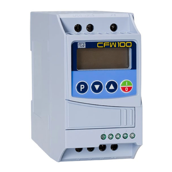
About the CFW100 3 ABOUT THE CFW100 The frequency inverter CFW100 is a high performance product which enables speed and torque control of three- phase induction motors. This product provides the user with the options of vector (VVW) or scalar (V/f) control, both programmable according to the application. - Page 28 About the CFW100 Frame size A Frame sizes B and C 1 – HMI 2 – Mounting bracket (DIN-rail mountingN) 3 – Front cover 4 – Fan with mounting bracket Figure 3.2: Main components of the CFW100 3-2 | CFW100 Return Advance...
-
Page 29: Hmi And Basic Programming
1. At the end of this level, the modified value is saved when the key is pressed. Figure 4.3 on page 4-2 illustrates the basic browsing of the operating modes of the HMI. CFW100 | 4-1 Return Advance... - Page 30 When the inverter is in the alarm state, the main display indicates the number of the alarm in the format Axxx. The browsing is allowed after pressing the key, and then the indication “A” is displayed on the Unit of measurement display, flashing until the situation causing the alarm is solved. 4-2 | CFW100 Return Advance...
-
Page 31: Programming Basic Instructions
This parameter defines which parameter will be viewed on the HMI when the motor is enabled after initialization. P207 – Bar Graph Parameter Selection Adjustable 0 to 999 Factory P207 = 3 Range: Setting: Properties: Description: This parameter defines which parameter will be shown on the HMI Bar Graph. CFW100 | 5-1 Return Advance... - Page 32 This parameter allows setting the form of indication of parameters P001 and P002. P213 – Bar Graph Scale Factor Adjustable 1 to 9999 Factory Range: Setting: Properties: Description: This parameter configures the full scale (100 %) of the bar graph to indicate the parameter selected by P207. 5-2 | CFW100 Return Advance...
- Page 33 These parameters define which parameters (their respective values) will be viewed on the screen ( ) of the infrared remote control (available with the accessory CFW100-IOADR). For further details, refer to the Installation, Configuration and Operation Guide of the CFW100-IOADR I/O Expansion Module. P200 – Password...
-
Page 34: Backup Parameters
12 to 13 Reserved. In order to load the parameters of user to the CFW100 operating area (P204 = 7) it is necessary that this area be previously saved. The operation of uploading this memory (P204 = 7), can also be done via digital inputs (DIx). For further details referring to this programming, refer to section 12.5 DIGITAL INPUT on page... -
Page 35: Situations For Config Status
The CONFIG status is indicated by the HMI “ConF” status, as well as in parameters P006 and P680. Such status indicates that the CFW100 cannot enable the output PWM pulses because the inverter configuration is incorrect or incomplete. For further details about indications of CONFIG state on the HMI, refer to chapter 14 READING PARAMETERS on page 14-1. - Page 36 Programming Basic Instructions 5-6 | CFW100 Return Advance...
-
Page 37: Identification Of The Inverter Model And Accessories
Once the inverter model identification code is checked, it is necessary to interpret it in order to understand its meaning. Refer to chapter 2 General Information of the CFW100 user’s manual. Below are the parameters related to the inverter model which change according to the inverter model and version. - Page 38 Identification of the Inverter Model and Accessories Description: This parameter identifies the inverter model, distinguishing frame, supply voltage and rated current as per Table 6.2 on page 6-2. Table 6.2: Identification of the CFW100 models Voltage (V) Power Current (A) Frame Size P029...
- Page 39 Properties: Description: It defines the point at which automatic gradual reduction of the switching frequency occurs. That significantly improves the measurement of the output current at low frequencies and consequently the performance of the inverter. CFW100 | 6-3 Return Advance...
- Page 40 Identification of the Inverter Model and Accessories 6-4 | CFW100 Return Advance...
-
Page 41: Logical Command And Frequency Reference
Figure 7.1 on page 7-2. Parameters P221 and P222 define the frequency reference in the Local and Remote situations. This structure for the selection of the reference source is shown in Figure 7.2 on page 7-3. CFW100 | 7-1 Return Advance... - Page 42 Control word CONTROL WORD Direction of rotation Control word Run/ Stop ALL THE COMMAND AND REFERENCE SOURCES OF THE INVERTER LOC/REM Ramp Reference frequency REFERENCE FREQUENCY Reference frequency Figure 7.1: Block diagram for commands and references 7-2 | CFW100 Return Advance...
- Page 43 000 001 010 011 100 101 110 111 MULTISPEED RS-485 – USB Converter 9 - Serial/USB CFW100-RS-485 CFW100-CUSB Bluetooth Adapter CFW100-CBLT CANopen Master 11 - CANopen/ DeviceNet CFW100-CCAN SoftPLC 12 - SoftPLC Figure 7.2: Command selection structure CFW100 | 7-3 Return Advance...
- Page 44 12.1 ANALOG INPUTS on page 12-1. „ HMI: the reference value set by the keys and are contained in parametere P121. „ E.P.: electronic potentiometer; refer to section 12.5 DIGITAL INPUT on page 12-8. „ 7-4 | CFW100 Return Advance...
- Page 45 These parameters define the origin source for the “Run/Stop" command in the Local and Remote situation. This command corresponds to the functions implemented in any of the command sources able to enable the motor movement, that is, genera enable, ramp enable, forward run, reverse run, start, etc. CFW100 | 7-5 Return Advance...
-
Page 46: Reference Frequency
Although the parameters to adjust the reference have a wide range of values (0 to 300.0 Hz), the value applied to the ramp is limited by P133 and P134. Therefore, the values in module out of this range will have no effect on the reference. 7-6 | CFW100 Return Advance... -
Page 47: Backup Of The Speed Reference
If P120 = Backup by P121, the reference initial value is fixed by P121 at the enabling or power-up of the inverter. 7.2.3 Parameters for Reference Frequency P121 – Frequency Reference via HMI Adjustable 0.0 to 300.0 Hz Factory 3.0 Hz Range: Setting: Properties: CFW100 | 7-7 Return Advance... - Page 48 P105. This command may be activated by any of the sources, as per section 7.1 SELECTION FOR LOGICAL COMMAND AND FREQUENCY REFERENCE on page 7-1. The negative values determine a direction of rotation opposite to that defined by the inverter command word. 7-8 | CFW100 Return Advance...
- Page 49 DI1 or DI2, only one of those options is allowed; otherwise, the Config state (ConF), according to section 5.3 SITUATIONS FOR CONFIG STATUS on page 5-5, is activated to indicate parameterization incompatibility. CFW100 | 7-9 Return Advance...
-
Page 50: Reference Via Electronic Potentiometer
Accelerate and Decelerate E.P. inputs. Besides, you can monitor the action of the inputs individually, as well as the action of the reference backup (P120 = 1) when the Run/Stop command is opened and closed again. 7-10 | CFW100 Return... -
Page 51: Frequency Input Fi
The 13-bit Frequency Reference is a scale based on the motor rated frequency (P402) or on the motor rated frequency (P403). In the CFW100, parameter P403 is taken as the base to determine the frequency reference. Thus, the 13-bit frequency value has a range of 16 bits with signal, that is, -32768 to 32767; however, the rated frequency in P403 is equivalent to the value 8192. - Page 52 0: Acceleration and deceleration ramp by P100 and P101. Ramp 1: Acceleration and deceleration ramp by P102 and P103. Reserved 0: No function. Fault Reset 1: If in fault state, reset the fault. 8 to 15 Reserved 7-12 | CFW100 Return Advance...
-
Page 53: Control Via Hmi Inputs
Contrary to the network interfaces and SoftPLC, the digital inputs do not access the inverter control word directly, because there are several functions for DIx that are defined by the applications. Such digital input functions are detailed in section 12.5 DIGITAL INPUT on page 12-8. CFW100 | 7-13 Return Advance... - Page 54 Logical Command and Speed Reference 7-14 | CFW100 Return Advance...
-
Page 55: Available Motor Control Types
Additionally, proper configuration of the selected control mode parameters is essential to reach maximum performance. The CFW100 is equipped with three control modes for the three-phase induction motor, that is: V/f Scalar Control: for basic applications without output speed control. - Page 56 Setting P397 = 0 allows the slip compensation to be turned off in this situation. This option is particularly useful when the compensation during the motor deceleration is necessary. Refer to parameter P138 section 9.1 PARAMETERIZATION OF THE V/f SCALAR CONTROL on page 9-3 for further details on slip compensation. 8-2 | CFW100 Return Advance...
-
Page 57: Scalar Control
For test purposes, the inverter is turned on without motor or with a small motor with no load. „ Applications where the load connected to the inverter is not a three-phase induction motor. „ Applications that aim at reducing losses on the motor and inverter (Quadratic V/f). „ CFW100 | 9-1 Return Advance... - Page 58 V/f Scalar Control Figure 9.1: Block diagram of V/f scale control 9-2 | CFW100 Return Advance...
-
Page 59: Parameterization Of The V/F Scalar Control
P146 P145 P134 Output Figure 9.2: Curve V/f The factory default setting of the CFW100 defines a linear relation of the torque with the frequency by means of three points (P and P The points P [P136, 0 Hz], P... - Page 60 Output P146 P145 P134 frequency (Hz) Figure 9.4: Torque Boost Region for V/f control mode Output voltage (%) P142 P136 Output P145 P134 frequency (Hz) Figure 9.5: Torque Boost Region for Quadratic V/f control mode 9-4 | CFW100 Return Advance...
- Page 61 The block diagram of Figure 9.6 on page 9-6 shows the automatic compensation action IxR responsible for the increment of the voltage in the ramp output according to the increase of the active current. CFW100 | 9-5 Return Advance...
- Page 62 Eg.: load distribution in motors driven in parallel. Output voltage (%) P142 P143 P136 Δf P146 Output P145 P134 frequency(Hz) Figure 9.7: Slip compensation in an operation point of the standar V/f curve 9-6 | CFW100 Return Advance...
-
Page 63: Start-Up In V/F Mode
V/f Scalar Control 9.2 START-UP IN V/f MODE NOTE! Read chapter 3 Installation and Connection of the CFW100 user manual before installing, energizing or operating the inverter. Sequence for installation, verification, power up and start-up. 1. Install the inverter: according to chapter 3 Installation and Connection of the user’s manual, making all the power and control connections. - Page 64 V/f Scalar Control 9-8 | CFW100 Return Advance...
-
Page 65: V W Vector Control
10 V V W VECTOR CONTROL The V V W vector control mode (Voltage Vector WEG) uses a control method with a much higher performance than the V/f control because of the load torque estimation and of the control of the magnetic flux in the air gap, as per scheme of Figure 10.1 on page... - Page 66 V V W Vector Control Figure 10.1: V V W control flow 10-2 | CFW100 Return Advance...
-
Page 67: Vvw Vector Control Parameterization
Below are described the parameters to configure the V V W vector control setting. This data is easily obtained on WEG standard motor nameplates, however in older motors or motors made by other manufacturers, the data may not be readily available. In those cases, it is recommended first contact the motor manufacturer, measure or calculate the desired parameter. - Page 68 1 = 0.25 HP (0.19 kW) Setting: 2 = 0.33 HP (0.25 kW) 3 = 0.50 HP (0.37 kW) 4 = 0.75 HP (0.55 kW) 5 = 1 HP (0.75 kW) Properties: cfg, V V W 10-4 | CFW100 Return Advance...
-
Page 69: Start-Up In V V W Mode
5. Activation of the VVW control: set P202 = 5 and parameters P399, P400, P401, P402, P403, P404 and P407 according to the motor nameplate. Also set the value of P409. If some of those data are not available, enter the approximate value by calculation or by similarity with WEG standard motor – see Table 10.1 on page 10-3. - Page 70 If necessary, change the content of “P407 – Motor Rated „ Power Factor”. If necessary, change the content of “P409 – Stator Resistance”. „ Press the key for the next parameter. „ Figure 10.2: Start-up of the V V W mode 10-6 | CFW100 Return Advance...
-
Page 71: Functions Common To All The Control Modes
(P134) and the time for a linear deceleration from the maximum frequency zero. In the CFW100, three ramps with different functions were implemented: Ramp – standard for most functions. - Page 72 “S”, aiming at reducing the mechanical shocks on the load, as shown in Figure 11.1 on page 11-2. Output frequency Linear ramp t (s) Ramp S Acceleration time Deceleration time (P100/P102) (P101/P103) Figure 11.1: S or Linear ramp 11-2 | CFW100 Return Advance...
-
Page 73: Dc Link Voltage And Output Current Limitation
Use recommended for the drive of loads that require braking torques at constant frequency in the inverter „ output. For example, the drive of loads with eccentric shaft as in sucker rod pumps; another application is the handling of loads with balance like in the translation in overhead cranes. CFW100 | 11-3 Return Advance... - Page 74 Figure 11.3 on page 11-5 Figure 11.4 on page 11-5 show the example chart. RAMP P100-P104 Reference Output frequency P001 P002 hold error ≥ 0 P004 P151 Figure 11.2: Block diagram DC link voltage limitation 11-4 | CFW100 Return Advance...
-
Page 75: Output Current Limitation By "Ramp Hold" P150 = 2 Or 3
Actuation: if the motor current exceeds the value set in P135, a null value is forced for the frequency ramp input „ forcing the motor deceleration. When the motor current reaches a value below P135 the motor accelerates again. Look at Figure 11.5 on page 11-6. CFW100 | 11-5 Return Advance... -
Page 76: Flying Start / Ride-Through
Both functions assume the special case in which the motor is spinning in the same direction and at a frequency close to the frequency reference, thus, by immediately applying the frequency reference to the output and increasing the output voltage in ramp, the slip and the starting torque are minimized. 11-6 | CFW100 Return Advance... -
Page 77: Flying Start Function
F021 (undervoltage on the DC link). If the supply voltage returns before, the inverter will enable the pulses again, imposing the frequency reference instantly (like in the Flying Start function) and making a voltage ramp with time defined by parameter P331. Refer to Figure 11.6 on page 11-8. CFW100 | 11-7 Return Advance... -
Page 78: Dc Braking
0.0 to 15.0 s 0.0 s Range: Setting: Properties: Description: DC braking duration at the start. DIRECT CURRENT INJECTION AT START Output frequency Time P299 P302 DC braking Time Stop Figure 11.7: DC Braking actuation at start 11-8 | CFW100 Return Advance... - Page 79 This parameter sets the DC voltage (DC Braking torque) applied to the motor during the braking. The setting must be done by gradually increasing the value of P302, which varies from 0.0 to 100.0 % of the rated braking voltage, until the desired braking is obtained. CFW100 | 11-9 Return Advance...
-
Page 80: Avoided Frequency
The passage by the avoided frequency band (2xP306) is done through acceleration/deceleration ramp. The function does not operate correctly if two bands of “Avoided Frequency” overlap. Output frequency 2 x P306 P304 2 x P306 P303 Reference Figure 11.9: Actuation of the avoided frequency 11-10 | CFW100 Return Advance... -
Page 81: Digital And Analog Inputs And Outputs
Digital and Analog Inputs and Outputs 12 DIGITAL AND ANALOG INPUTS AND OUTPUTS This section presents the parameters to configure the CFW100 inputs and outputs. This configuration depends on the plug-in module, as per Table 12.1 on page 12-1. Table 12.1: I/O configurations of the CFW100... - Page 82 0.000 to 9.999 1.000 Range: Setting: P234 – AI1 Input Offset Adjustable -100.0 to 100.0 % Factory 0.0 % Range: Setting: P235 – AI1 Input Filter Adjustable 0.00 to 16.00 s Factory 0.00 s Range: Setting: Properties: 12-2 | CFW100 Return Advance...
- Page 83 In the CFW100-IOAR and CFW100-IOA accessories, the DIP Switch S1:1 set to ON configures the input AI1 for signal in current. For further details, refer to the Installation, Configuration and Operation Guide of the CFW100- IOAR and CFW100-IOA I/O Expansion Modules.
-
Page 84: Ntc Sensor Input
Therefore, the filter response time is around three times the value of this time constant. 12.2 NTC SENSOR INPUT The CFW100-IOADR accessory has an exclusive analog input to connect an NTC sensor. The temperature reading parameter is described below. - Page 85 P134 Total Output Current RMS 2xP295 Active Current 2xP295 Torque on the Motor in relation to the rated torque 200.0 % SoftPLC scale for analog output 16383 Ixt overload of the motor (P037) 100 % CFW100 | 12-5 Return Advance...
-
Page 86: Frequency Input
This parameter configures if the analog output signal will be in current or voltage, with direct or reverse reference. Besides setting this parameter, it is necessary to position a DIP switch of the CFW100-IOA module – S1:2 in ON configures AO1 for output signal in voltage. - Page 87 P265 be ignored, as well as the value of bit "2" of P012 is maintained in "0". On the other hand, when set to "0", the frequency input is inactive, keeping parameter P022 in zero. CFW100 | 12-7 Return Advance...
-
Page 88: Digital Input
0 to 3000 Hz in 10 Vpp. The time constant of the digital filter for the frequency input is defined by means of parameter P245. 12.5 DIGITAL INPUT Below is a detailed description of the parameters for the digital inputs. 12-8 | CFW100 Return Advance... - Page 89 P265 – Function of Digital Input DI3 P266 – Function of Digital Input DI4 P267 – Function of Digital Input DI5 P268 – Function of Digital Input DI6 P269 – Function of Digital Input DI7 CFW100 | 12-9 Return Advance...
- Page 90 P224 = 1 or P227 = 1 Safety Switch Command P224 = 1 or P227 = 1 Function 1 Application Function 2 Application Function 3 Application Function 4 Application Function 5 Application Function 6 Application Function 7 Application Function 8 Application 12-10 | CFW100 Return Advance...
- Page 91 Figure 12.6: Example of the General Enable function c) QUICK STOP When inactive, it disables the inverter by the emergency deceleration (P107). Acceleration P107 - ramp Deceleration Output ramp frequency Time Active Inactive Time Figure 12.7: Example of the Quick Stop function CFW100 | 12-11 Return Advance...
- Page 92 Figure 12.9: Example of the Start / Stop NOTE! All the digital inputs set for General Enable, Fast Stop, Forward Run/Reverse Run and Start/Stop must be in the “Active” state so that the inverter can enable the motor spin. 12-12 | CFW100 Return Advance...
- Page 93 P120 = 2, the initial value will be the reference via P121 keys. Besides, the E.P. reference can be reset by activating both Accelerate E.P. and Decelerate E.P. inputs when the inverter is disabled. CFW100 | 12-13 Return Advance...
- Page 94 DIx - 2 ramp Inactive Time P102 P103 P100 P101 Output frequency Time Figure 12.13: Example of the 2 Ramp function l) NO EXTERNAL ALARM If DIx is inactive, the inverter will activate the external alarm A090. 12-14 | CFW100 Return Advance...
- Page 95 Output frequency Time Active Pulse DIx - Accelerate/ Turn Turn ON Inactive Time Active Pulse DIx - Decelerate/ Turn Turn OFF Inactive Time Figure 12.14: Example of the Accelerate Turn ON / Decelerate Turn OFF CFW100 | 12-15 Return Advance...
-
Page 96: Input For Infrared Receiver
Expansion Module. 12.7 DIGITAL OUTPUTS The CFW100 can activate up to three relay digital outputs (DO1 to DO3) – one with the CFW100-IOAR accessory or three with the CFW100-IOADR accessory connected to the product. The configuration of the digital output parameters is according to the detailed description below. - Page 97 Properties: Description: Using this parameter, it is possible to view the CFW100 digital output status. The P013 value is indicated in hexadecimal, where each bit of the number indicates the status of a digital output, that is, if BIT0 is “0”, DO1 is inactive; if BIT0 is “1”, DO1 is active, and so on, up to DO3.
- Page 98 These parameters set the hysteresis and actuation level on the Fx output frequency signal and on the F* ramp input of the relay digital output. In this way, the relay commutation levels are “P281 + P282” and “P281 - P282”. 12-18 | CFW100 Return...
- Page 99 Current level to activate the relay output in the Is>Ix (6) and Is<Ix (7) functions. The actuation occurs on a hysteresis with upper and lower level by: P290 – 0.05xP295, that is, the equivalent value in Amperes for 5 % of P295 below P290. CFW100 | 12-19 Return Advance...
- Page 100 Digital and Analog Inputs and Outputs 12-20 | CFW100 Return Advance...
-
Page 101: Faults And Alarms
The alarm works as a warning for the user of critical operating conditions and that may cause a fault if the situation is not corrected. Refer to chapter 6 of the CFW100 user manual and the chapter QUICK REFERENCE OF PARAMETERS, ALARMS AND FAULTS on page 0-1 of this manual to obtain more information regarding Faults and Alarms. -
Page 102: Igbts Overload Protection (F051 And A050)
PWM pulses when the output current is high. Fault F070 corresponds to a current surge between output phases. The protection current level depends on the used power module so as the protection is effective, still this value is well above the inverter rated operating current (P295). 13-2 | CFW100 Return Advance... -
Page 103: Link Voltage Supervision (F021 And F022)
F033. 13.6 REMOTE HMI COMMUNICATION FAULT ALARM (A700) After connecting the remote HMI to the CFW100 terminals, the communication with the HMI is supervised so that alarm A700 is activated whenever this communication link is broken. 13.7 REMOTE HMI COMMUNICATION ERROR FAULT (F701) The condition for fault F701 is the same as that of alarm A700, but it is necessary that the HMI be the source for some command or reference (HMI Keys option) in parameters P220 to P228. -
Page 104: External Alarm (A090)
0.0 to 10.0 A Factory Range: Setting: Properties: Description: They indicate the output current at the moment of the occurred fault. P052 – Last Fault DC Link Adjustable 0 to 524 V Factory Range: Setting: Properties: 13-4 | CFW100 Return Advance... -
Page 105: Fault Auto-Reset
Adjustable 0 to 255 s Factory Range: Setting: Properties: Description: It defines the interval after a fault to activate the inverter auto-reset. If the value of P340 is zero the fault autoreset function is disabled. CFW100 | 13-5 Return Advance... - Page 106 Faults and Alarms 13-6 | CFW100 Return Advance...
-
Page 107: Reading Parameters
It indicates the DC link direct current voltage in (V). P005 – Output Frequency (Motor) Adjustable Factory 0.0 to 300.0 Hz Range: Setting: Properties: Description: Real frequency instantly applied to the motor in Hertz (Hz). CFW100 | 14-1 Return Advance... - Page 108 It indicates the line voltage in inverter output, in Volts (V). P009 – Motor Torque Adjustable Factory -200.0 to 200.0 % Range: Setting: Properties: ro, V V W Description: It indicates the torque developed by the motor in relation to the rated torque. 14-2 | CFW100 Return Advance...
- Page 109 13.1 MOTOR OVERLOAD PROTECTION (F072 AND A046) on page 13-1. P047 – CONFIG Status Adjustable Factory 0 to 999 Range: Setting: Properties: Description: This parameter shows the origin situation of CONFIG mode. Refer to section 5.3 SITUATIONS FOR CONFIG STATUS on page 5-5. CFW100 | 14-3 Return Advance...
- Page 110 The reading parameters P295 and P296 are detailed in the section 6.1 INVERTER DATA on page 6-1. The reading parameter P680 is detailed in the section 7.3 CONTROL WORD AND INVERTER STATUS on page 7-11. 14-4 | CFW100 Return Advance...
-
Page 111: Communication
Modbus, CANopen and DeviceNet. For further details referring to the inverter configuration to operate in those protocols, refer to the CFW100 user’s manual for communication with the desired network. Below are listed the parameters related to the communication. -
Page 112: Can - Canopen / Devicenet Interface
P710 – DeviceNet I/O Instances P711 – DeviceNet Reading #3 P712 – DeviceNet Reading #4 P713 – DeviceNet Reading #5 P714 – DeviceNet Reading #6 P715 – DeviceNet Writing #3 P716 – DeviceNet Writing #4 15-2 | CFW100 Return Advance... -
Page 113: Commands And Communication Status
P721 – CANopen Communication Status P722 – CANopen Node Status Description: Parameters used for monitoring and controlling the CFW100 inverter by using the communication interfaces. For detailed description, refer to the communication manual (User) according to the interface used, available in www.weg.net. - Page 114 Communication 15-4 | CFW100 Return Advance...
-
Page 115: Softplc
CFW100 firmware version. In this case, it is necessary that the user recompile the project on the WLP, considering the new CFW100 version and redo the download. If that is not possible, the upload of this application can be done with the WLP, provided that the application password is known or is not enabled. - Page 116 SoftPLC Description: These are parameters whose use is defined by the SoftPLC function. NOTE! For further information on the use of the SoftPLC function, refer to the CFW100 SoftPLC manual. 16-2 | CFW100 Return Advance...
Need help?
Do you have a question about the CFW100 and is the answer not in the manual?
Questions and answers