
Related Manuals for WEG CFW-10


Summary of Contents for WEG CFW-10
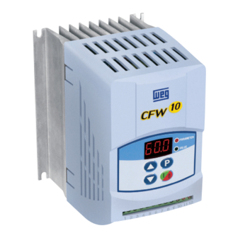
- Page 1 Motors | Automation | Energy | Transmission & Distribution | Coatings Frequency Inverter CFW-10 User's Guide...
- Page 3 FREQUENCY INVERTER MANUAL CFW-10 Series: Software: version 2.XX Language: English Document: 0899.5202 / 10 04/2015 ATTENTION! It is very important to check if the inverter software version is the same as indicated above.
- Page 4 Sumarry of Revisions The table below describes all revisions made to this manual. Revision Description Section First Edition Addition of the CFW10 MECII and addition of the EMC filter for MECI. General revision. Addition of the CFW10 Size III and Addition of the EMC filter for sizes II and III.
-
Page 5: Table Of Contents
1.3 Preliminary Recommendations ........ 12 CHAPTER 2 General Information 2.1 About this Manual ........... 14 2.2 Software Version ............ 14 2.3 About the CFW-10 ..........15 2.4 CFW-10 Identification ..........19 2.5 Receiving and Storing ..........21 CHAPTER 3 Installation and Connection 3.1 Mechanical Installation .......... - Page 6 CONTENTS 3.3.2 Specification of the Emission and Immunity Levels ..........40 3.3.3 Inverter and Filters ..........41 3.3.4 Characteristics of the EMC Filters ..... 43 CHAPTER 4 Keypad (HMI) Operation 4.1 Keypad (HMI) Description ........47 4.2 Use of the Keypad (HMI) ......... 48 4.2.1 Keypad (HMI) Operation ........
- Page 7 CONTENTS CHAPTER 7 Diagnostics and Troubleshooting 7.1 Faults and Possible Causes ........96 7.2 Troubleshooting ............98 7.3 Contacting WEG ............. 99 7.4 Preventive Maintenance .......... 99 7.4.1 Cleaning Instructions ........100 CHAPTER 8 Options and Accessories 8.1 RFI Filter ............. 101 8.2 Line Reactor ............
-
Page 8: Parameters
CFW-10 - QUICK PARAMETER REFERENCE QUICK PARAMETER REFERENCE, FAULT AND STATUS MESSAGES Software: V2.XX Application: Model: Serial Number: Responsible: Date: I. Parameters Factory User Parameter Function Adjustable Range Unit Page Setting Setting Access Parameter 0 to 4, 6 to 999 = Read... - Page 9 CFW-10 - QUICK PARAMETER REFERENCE Factory User Parameter Function Adjustable Range Unit Page Setting Setting V/F Control Manual Torque Boost 0.0 to 100 20.0 P136 (I x R Compensation ) Automatic Torque Boost 0.0 to 100 P137 (Automatic I x R Compensation) Slip Compensation 0.0 to 10.0...
- Page 10 CFW-10 - QUICK PARAMETER REFERENCE Factory User Parameter Function Adjustable Range Unit Page Setting Setting Forward/Reverse 0 = Forward P231 Selection 1 = Reverse 2 = Commands Analog Inputs(s) Analog Input AI1 Gain 0.0 to 999 P234 Analog Input AI1 Signal...
-
Page 11: Fault Messages
CFW-10 - QUICK PARAMETER REFERENCE Factory User Parameter Function Adjustable Range Unit Page Setting Setting Fx and Ix Fx Frequency 0.0 to P134 P288 Ix Current 0.0 to 1.5 x I P295 P290 Inverter Data Rated Inverter Readonly P295 Current (I Parameter 10.0... -
Page 12: Safety Notices
CHAPTER 1 SAFETY NOTICES This manual contains necessary information for the correct use of the CFW-10 Variable Frequency Drive. This manual has been written for qualified personnel with suitable training and technical qualification to operate this type of equipment. 1.1 SAFETY... - Page 13 In this manual, qualified personnel are defined as people that are trained to: 1. Install, ground, power up and operate the CFW-10 according to this manual and the local required safety procedures; 2. Use of safety equipment according to the local regulations;...
-
Page 14: General Information
The CFW-10 is very flexible and allows the operation in many different modes as described in this manual. As the CFW-10 can be applied in several ways, it is impossible to describe here all of the application possibilities. WEG does not accept any responsibility when the CFW-10 is not used according to this Manual. -
Page 15: About The Cfw-10
(DI1 to DI4) WITH DSP Relay Analog Output Input (RL1) (AI1) Figure 2.1 - CFW-10 Block Diagram for models 1.6 A, 2.6 A and 4.0 A / 200-240 V (single-phase) and 1.6 A, 2.6 A, 4.0 A and 7.3 A/200-240 V (three-phase) - Page 16 BETWEEN POWER AND CONTROL "CCP10" Digital CONTROL Inputs (DI1 to DI4) BOARD WITH DSP Relay Analog Output Input (AI1) (RL1) Figure 2.2 - CFW-10 Block Diagram for model 7.3 A and 10.0 A/200-240 V (single-phase) and 10.0 A and 15.2 A/200-240 V (three-phase)
- Page 17 POWER SUPPLY FOR ELETRONICS AND INTERFACE BETWEEN POWER AND CONTROL. Digital "CCP10" Inputs CONTROL (DI1 to DI4) BOARD WITH DSP Analog Relay Input Output (AI1) (RL1) Figure 2.3 - CFW-10 Block Diagram for model 1.6 A and 2.6 A/110-127 V...
- Page 18 RFI Filter POWER CONTROL POWER SUPPLY FOR ELETRONICSAND INTERFACE BETWEEN POWER AND CONTROL Digital "CCP10" Inputs CONTROL (DI1 to DI4) BOARD WITH DSP Analog Relay Input Output (AI1) (RL1) Figure 2.4 - CFW-10 Block Diagram for model 4.0 A /110-127 V...
-
Page 19: Identification
CHAPTER 2 - GENERAL INFORMATION 2.4 CFW-10 IDENTIFICATION Software Version Part Number CFW-10 Model Manufacturing Date Rated Input Data Rated Output Data (Voltage, Current, etc) (Voltage, Frequency) Serial Number Lateral Nameplate CFW-10 Figure 2.5 - Description and Location of the Nameplate... - Page 20 CHAPTER 2 - GENERAL INFORMATION...
-
Page 21: Receiving And Storing
The equipment has not been damaged during transport. If any problem is detected, contact the carrier immediately. If the CFW-10 is not installed immediately, store it in a clean and dry room (storage temperatures between -25 °C and 60 °C). Cover it to protect it against dust, dirt or other contamination. -
Page 22: Installationand Connection
External dimensions and mounting holes for the CFW-10 shall be 3.1.2 Dimensional of according to figure 3.1 and table 3.1. CFW-10 MOUTING BASE FRONTAL SIDE VIEW SIDE VIEW VIEW VIEW (STANDARD VERSION) (COLD PLATE VERSION) Figure 3.1 - Dimensional of CFW-10 - Sizes 1, 2 and 3... - Page 23 CHAPTER 3 - INSTALLATION AND CONNECTION Size 3 Size 2 Size 1 Figure 3.1 - Dimensional of CFW-10 - Sizes 1, 2 and 3 Dimensions Fixing Base Width Height Depth Mounting W eight Degree of Model Sc rew [k g]...
- Page 24 Table 3.1 b) Cold Plate Version, installation data (dimensions in mm (in)) – Refer to Section 9.1 The Cold Plate version was designed in order to allow mounting the “CP” CFW-10 frequency inverter in any heat dissipation surface, since following recommendations are fulfilled.
-
Page 25: Mounting Specification
CHAPTER 3 - INSTALLATION AND CONNECTION 3. Use (M4) mounting screws in order to fasten the frequency inver- ter to the base plate. 4. After drilling the holes, clean the contact surface of the backing plate and coat it with a thin thermal paste layer, or with a heat conducting foil or similar product (approx. -
Page 26: Panel Mounting
Follow also all applicable local standards for electrical installations. DANGER! Be sure the AC input power has been disconnected before making any terminal connection. DANGER! The CFW-10 shall not be used as an emergency stop device. Use additional devices proper for this purpose. -
Page 27: Power And Grounding Terminals
Models 7.3 A and 10 A/200-240 V and 4.0 A/110-127 V (single-phase) L/L1 N/L2 BR + UD U c) Models 1.6 A, 2.6 A, 4.0 A, 7.3 A/200-240 V (three-phase) d) Models 10.0 A and 15.2 A/200-240 V (three-phase) Figure 3.4 a) b) c) d) - CFW-10 Power Terminals... -
Page 28: Location Of The Power, Grounding And Control Connections
For instance: PLC’s, temperature monitoring devices, thermocouples, etc. Table 3.3 presents minimum cable diameter and circuit breaker rating for the CFW-10. Tightening torque shall be as indicated in table 3.4. All power wiring (cooper) shall be rated for 70 ºC minimum. Motor... -
Page 29: Power Connections
CHAPTER 3 - INSTALLATION AND CONNECTION NOTE! Cable dimensions indicated in table 3.3 are reference values only. Installation conditions and the maximum acceptable line voltage drop shall be considered when sizing the power cables. Power Cables Model Lbf.in SINGLE-PHASE 1.6 A / 200-240 V 8.68 2.6 A / 200-240 V 8.68... - Page 30 CHAPTER 3 - INSTALLATION AND CONNECTION b) Models 7.3 A to 10 A/200-240 V and 4.0 A/110-127 V (single-phase) L/L1 N/L2 SHIELDING Braking Resistor L/L1 N/L2 POWER SUPPLY c) Models 1.6 A, 2.6 A, 4.0 A and 7.3 A/200-240 V (three-phase) SHIELDING POWER SUPPLY Figure 3.6 b) c) - Grounding and power supply connections...
-
Page 31: Ac Input Connection
The CFW-10 is capable of withstanding up to 30.000 symmetrical rms Amperes at 127 V/240 V. If the CFW-10 is installed in networks with higher symmetrical rms currents (> 30.000 Amps), an appropriate protection mean shall be provided (fuses or circuit breaker). -
Page 32: Output Connection
CHAPTER 3 - INSTALLATION AND CONNECTION 3.2.4.2 Output The drive has electronic protection against motor overload. This Connection protection shall be set according to the specific motor. When the same drive is connected to several motors, individual overload relays shall be used for each motor protection. - Page 33 CHAPTER 3 - INSTALLATION AND CONNECTION Figure 3.7 - Grounding connections for more than one drive NOTE! Do not use the neutral conductor for grounding purposes. ATTENTION! The AC input for the drive supply must have a grounded neutral conductor. Electromagnetic Interference (EMI) Shielded cable or metallic conduit shall be used for motor wiring when electromagnetic interference (EMI) caused by the drive interferes in...
-
Page 34: Signal And Control Connections
If the input current from (4 to 20) mA is used as standard, do not forget to set the Parameter P235 which defines the signal type at AI1. The analog input AI1 and the Relay output, (XC1:6…12) are not available on Clean version of the CFW-10. - Page 35 CHAPTER 3 - INSTALLATION AND CONNECTION During the signal and control wire installation note the following: 1) Cable cross section: (0.5 to 1.5) mm² / (20 to 14) AWG. 2) Max. Torque: 0.50 N.m (4.50 lbf.in). 3) XC1 wiring must be connected with shielded cables and installed at least 10 cm (3.9 in) minimum separately from other wiring (power, control at 110/220 V, etc) for lengths up to 100 m (330 ft) and 25 cm (9.8 in) minimum for total lengths over...
-
Page 36: Typical Terminal Connections
When a line fault occurs by using this type of connection with switch S3 at position "RUN", the motor will be enabled automatically as soon as the line is re-established. Function 2 configuration is not possible on CFW-10 Clean version. - Page 37 CHAPTER 3 - INSTALLATION AND CONNECTION Connection 3 Start/Stop function enabling (three-wire control): Set DI1 to Start: P263 = 13 Set DI2 to Stop: P264 = 14 Set P229 = 1 (commands via terminals) if you want the 3-wire control in local mode.
-
Page 38: European Emc Directive - Requirements For Conforming Installations
The CFW-10 inverter series was designed considering all safety and Directive - EMC (ElectroMagnetic Compatibility) aspects. Requirements The CFW-10 units do not have an intrinsic function until connected for Conforming with other components (e. g. a motor). Therefore, the basic product is Installations not CE marked for compliance with the EMC Directive. -
Page 39: Installation
RFI filter XC1 1 to 12 Transformer L1/L L1/L Motor CFW-10 L2/N L2/N Metalic cabinet when necessary Grounding rod Protective Grounding Figure 3.13 - EMC filter connection - general condition The following items are required in order to have an appropriated... -
Page 40: Specification Of The Emission And Immunity Levels
CHAPTER 3 - INSTALLATION AND CONNECTION 3.3.2 Specification of the Emission and Immunity Levels Basic standard EMC phenomenon Level for test method Emission: “First environment” , restricted distribution Class B, or; Conducted emissions (mains “First environment” , restricted distribution (4) (5) terminal disturbance voltage - freq Class A1, or;... -
Page 41: Inverter And Filters
CHAPTER 3 - INSTALLATION AND CONNECTION (5) For installation in residential environments with conducted emission level Class A1 (according to table 3.5.2), please, consider the following: This is a product of restricted sales distribution class according to the product standard IEC/EN61800-3 (1996) + A11 (2000). In a domestic environment this product may cause radio interference in which case the user may be required to take adequate measures. - Page 42 Maximum motor cable length is 3 meters (9.8 ft). Note: Maximum switching frequency is 5 kHz. Table 3.5.2 - List of frequency drive models, EMC filters and EMC categories NOTE! The CFW-10 inverters with three-phase supply do not have EMC filters.
-
Page 43: Characteristics Of The Emc Filters
CHAPTER 3 - INSTALLATION AND CONNECTION 3.3.4 Characteristics of the EMC Filters Footprint / Booksize Model B84142A0012R212 (EPCOS) Supply voltage: 250 V, 50/60 Hz Current: 12 A Weight: 0.95 Kg (2.1 lb) a) Model footprint/booksize B84142A0012R212 (EPCOS) Terminals 2.5 mm Tightening torque of screw max. - Page 44 CHAPTER 3 - INSTALLATION AND CONNECTION Footprint / booksize Model B84142B18R212 (EPCOS) Supply Voltage: 250 V, 50/60 Hz Current: 18 A Weight: 1.3 kg (2.9 lb) b) Footprint/booksize model B84142B18R212 (EPCOS) Terminals 2.5 mm Tightgning torque of screw max. 0.5 Nm 5 x 45 º...
- Page 45 CHAPTER 3 - INSTALLATION AND CONNECTION Footprint / booksize Model B84142B22R212 (EPCOS) Supply voltage: 250 V, 50/60 Hz Current: 22 A Weight: 1.4 kg (3 lb) c) Footprint/booksize Model B84142B22R212 (EPCOS) Terminals 6 mm Tightgning torque of screw max. 1.2 Nm 5 x 45 º...
- Page 46 24±1 ±1 40±1 Note: Figure dimensions are in mm. Figure 3.15 a) b) - Drawing of the Standard Filter NOTE! The declaration of conformity CE is available on the website www.weg.net or on the CD, which comes with the products.
-
Page 47: Keypad (Hmi) Operation
Inverter parameters arrangement; Alteration mode parameters (programming); Description of the status indicators. The standard CFW-10 keypad has a LED display with 3 digits of 7 4.1 KEYPAD (HMI) segments, 2 status LEDs and 4 keys. Figure 4.1 shows the front... -
Page 48: Use Of The Keypad (Hmi)
Potentiometer for the output frequency variation (only in the Plus version). 4.2.1 Keypad (HMI) All functions relating to the CFW-10 operation (Start/Stop, Increment/ Operation Decrement of the Speed Frequency) can be performed through the HMI selection. For factory default programming of the inverter, all keypad keys are enabled. -
Page 49: Inverter Status - Hmi Display
P121. NOTE! On CFW-10 Plus version, the motor frequency setting function is made through the HMI potentiometer. However, it is possible to set the mo- tor frequency through the keys since P221/P222 parameters were programmed. -
Page 50: Read-Only Variables
CHAPTER 4 - KEYPAD (HMI) OPERATION 4.2.3 Read-Only Parameters from P002 to P008 are reserved for the display of read- Variables only variables. When the inverter is powered up, the display will indicate the value of the Parameter P002 (output frequency value). 4.2.4 Parameter All inverter settings are made through parameters. - Page 51 CHAPTER 4 - KEYPAD (HMI) OPERATION NOTE! (1) For parameters that can be changed with the running motor , the inverter will use the new value immediately after it has been set. Forparameters that can be changed only with stopped motor , the inverter will use this new value only after the key is pressed.
-
Page 52: Start-Up
CHAPTER 5 START-UP This Chapter provides the following information: How to check and prepare the inverter before power-up; How to power-up and check for proper operation; How to operate the inverter when it is installed according to the typical connections (See Electrical Installation). The inverter shall be installed according to Chapter 3 - Installation 5.1 PRE-POWER CHECKS... -
Page 53: Start-Up
CHAPTER 5 - START-UP 5.3 START-UP DANGER! Even after the AC power supply has been disconnected, high voltages may be still present. Wait at least 10 minutes after powering down to allow full discharge of the capacitors. 5.3.1 Start-up The sequence below is valid for the connection 1 (refer to Section Operation via 3.2.6). -
Page 54: Start-Up Operation Via Terminals
CHAPTER 5 - START-UP 5.3.2 Start-up The sequence below is valid for the Connection 2 (refer to Section Operation Via 3.2.6). Inverter must be already installed and powered up according Terminals to Chapter 3 and Section 5.2. Connections according to figures 3.6 and 3.10. ACTION HMI DISPLAY DESCRIPTION... -
Page 55: Detailed Parameter Description
CHAPTER 6 DETAILED PARAMETER DESCRIPTION This chapter describes in detail all CFW-10 parameters and functions. SYMBOLS Please find below some symbols used in this chapter: AIx = Analog input number x. AO = Analog output. DIx = Digital input number x. -
Page 56: Frequency Reference Sources
2 digital inputs (DI1 and DI4) - see P221, P222, P263 and P266; HMI Potentiometer – the reference can be changed through the HMI potentiometer (Only available on CFW-10 Plus version). Figure 6.1 shows through a diagram block the frequency reference definition to be used by the inverter. - Page 57 CHAPTER 6 - DETAILED PARAMETER DESCRIPTION Frequency Reference Selection P221 or P222 Potentiometer 3 - HMI Reference Potentiometer Keypad Reference 0 - Keypad (P121) P271 7 - Input Frequency P263 = 7/8 P264 = 7/8 P265 = 7/8 P124 to P131 P266 = 7/8 P131 P130...
- Page 58 CHAPTER 6 - DETAILED PARAMETER DESCRIPTION P151 DC Link Power Regulation Supply P151 P100 P101 P136, P137, P138, P142, P133 P134 P202 P295 P145 Acceleration and Deceleration Inverter Ramp Control (V/F or P102 P103 Vector) Frequency Reference Limits Acceleration and Deceleration 3Ø...
-
Page 59: Commands
CHAPTER 6 - DETAILED PARAMETER DESCRIPTION 6.2.3 Commands The inverter has the following commands: PWM pulse enabling/ disabling, definition of the direction of rotation and JOG. As the frequency reference, also the inverter commands can de defined in several ways. The main command sources are: Via keypad key -key Via control terminals (XC1) - digital inputs. -
Page 60: Parameter Listing
Regulation Parameters Programmable values that cab be used by the CFW-10 functions. Configuration Parameters They define the inverter characteristics, the functions to be executed, as well as the input/output functions of the control board. -
Page 61: Access And Read Only Parameters - P000 To P099
CHAPTER 6 - DETAILED PARAMETER DESCRIPTION 6.3.1 Access and Read Only Parameters - P000 to P099 Range [Factory Setting] Parameter Description / Notes 0 to 999 Releases the access to change the parameter values. P000 The password is 5. Access [ 0 ] The use of the password is always active. -
Page 62: Regulation Parameters - P100 To P199
CHAPTER 6 - DETAILED PARAMETER DESCRIPTION 6.3.2 Regulation Parameters - P100 to P199 Range [Factory Setting] Parameter Description / Notes Indicates the value of the process variable used as 0.0 to 999 P040 PID regulator feedback, in percent (%). Variable Process [ - ] The PID function is only available from V.2.00 software version. - Page 63 CHAPTER 6 - DETAILED PARAMETER DESCRIPTION Range [Factory Setting] Parameter Description / Notes Output Frequency (Motor Speed) Linear 50 % S ramp 100 % S ramp t (s) accel. time decel. time (P100/102) (P101/103) Figure 6.4 - S or linear Ramp It is recommended to use the S ramp with digital frequency/speed references.
- Page 64 CHAPTER 6 - DETAILED PARAMETER DESCRIPTION Range [Factory Setting] Parameter Description / Notes P120 = 3, works according P120 = 1, however, only update the backup after a start when the output frequency value reaches the previously backup stored value. P133 to P134 Defines the keypad reference value that can be set by P121...
- Page 65 CHAPTER 6 - DETAILED PARAMETER DESCRIPTION Range [Factory Setting] Parameter Description/Notes P133 to P134 The frequency reference is defined by the status of the P128 Multispeed Ref. 5 [ 40.0 Hz ] digital inputs programmed to multispeed as shown in 0.1 Hz (<...
- Page 66 CHAPTER 6 - DETAILED PARAMETER DESCRIPTION Range [Factory Setting] Parameter Description / Notes 0.0 to P134 Defines the maximum and minimum output frequency P133 Minimum [ 3.0 Hz ] (motor) when inverter is enabled. Frequency 0.1 Hz (< 100 Hz); It is valid for any type of speed reference.
- Page 67 CHAPTER 6 - DETAILED PARAMETER DESCRIPTION Range [Factory Setting] Parameter Description / Notes b) P202 = 1 Output Voltage (% of the line voltage) P142 P136 Output frequency P145 Figure 6.6 b) cont. - V/F curve and details of the manual torque boost (I x R compensation) 0.0 to 100 % The automatic torque boost compensates for the...
- Page 68 CHAPTER 6 - DETAILED PARAMETER DESCRIPTION Range [Factory Setting] Parameter Description / Notes The parameter P138 is used in the motor slip compen- 0.0 to 10.0 P138 sation function. Slip [ 0.0 ] This function compensates the drop of the motor speed Compensation 0.1 % due to load, which is a inherent characteristic relating...
- Page 69 CHAPTER 6 - DETAILED PARAMETER DESCRIPTION Range [Factory Setting] Parameter Description / Notes Define the V/F curve used in V/Fcontrol (P202 = 0 or 1). 0 to 100 (1)(2) P142 These parameters allow changing the standard V/F Maximum Output [ 100 ] curve defined at P202 - programmable V/F curve.
- Page 70 CHAPTER 6 - DETAILED PARAMETER DESCRIPTION Range [Factory Setting] Parameter Description / Notes DC Link Voltage E01 - Overvoltage P151 Hardware limit Rated Ud CI Voltage Ud (P004) Time Output Frequency (Motor Speed ) Time Figure 6.12 - Deceleration curve with DC Link voltage regulation By this function an optimized deceleration time (minimum) is achieved for the driven load.
-
Page 71: Configuration Parameters - P200 To P398
CHAPTER 6 - DETAILED PARAMETER DESCRIPTION Range [Factory Setting] Parameter Description / Notes Prevents motor stalling during an overload. If motor load 0.2 x I to 2.0 x I P169 increases its current will increase too. If the motor Maximum Output [ 1.5 x P295 ] current attempts to exceed the value set at P169, the Current... - Page 72 CHAPTER 6 - DETAILED PARAMETER DESCRIPTION Range [Factory Setting] Parameter Description / Notes recommended for belt c onveyors, extruding machines, etc. - Quadratic V/F control: in this control mode the flux in the motor air gap is proportional to the output frequency up to the field weakening point (defined at P142 and P145).
- Page 73 CHAPTER 6 - DETAILED PARAMETER DESCRIPTION Range [Factory Setting] Parameter Description / Notes Selects or not the PID Regulator special function. 0 to 1 P203 Special Functions [ 0 - None ] P203 Special Function Selection None PID Regulator Table 6.6 - P203 configuration to use or not the PID regulator special function For PID Regulator special function see detailed description of the related parameters (P520 to P528).
- Page 74 For factory default setting, the local reference is via keys of the keypad and the remote reference is via analog input AI1. On CFW-10 Plus version, local reference via HMI potentiometer is the factory default setting.
- Page 75 CHAPTER 6 - DETAILED PARAMETER DESCRIPTION Range [Factory Setting] Parameter Description / Notes 0 to 2 Defines the direction of rotation. P231 Forward/Reverse - [ 2 - Commands] P231 Direction of rotation Local/Remote Always forward Modes Always reverse Commands as defined in P229 and P230 Table 6.9 - P231 programming to select rotation direction 0.0 to 999...
- Page 76 CHAPTER 6 - DETAILED PARAMETER DESCRIPTION Range [Factory Setting] Parameter Description / Notes This is shown in the block diagram below: P234 AI1' GAIN P235 OFFSET (P236) Figure 6.18 a) - Block diagram of the analog input A1 Following situation as example: AI1 is the voltage input (0-10 V - P235 = 0), AI1 = 5 V, P234 = 1.00 and P236 = -70 %.
- Page 77 CHAPTER 6 - DETAILED PARAMETER DESCRIPTION Range [Factory Setting] Parameter Description / Notes Note that there is always a dead zone at the starting of the curve where the frequency reference remains at the value of the minimum frequency (P133), even when the input signal is changed.
- Page 78 CHAPTER 6 - DETAILED PARAMETER DESCRIPTION Range [Factory Setting] Parameter Description / Notes 0 to 1 Defines the signal type of the analog input, as shown P235 in table below: Analog Input AI1 [ 0 ] Signal Signal Type P235 (0 to10) V or (0 to 20) mA (4 to 20) mA Table 6.11 - P235 setting according to signal type/excursion...
- Page 79 CHAPTER 6 - DETAILED PARAMETER DESCRIPTION Range [Factory Setting] Parameter Description / Notes 0 to 27 DI Parameter DI1 (P263), DI2 (P264), P266 Function DI3 (P265), DI4 (P266) Digital Input DI4 [4 - Not used (HMI) Forward run Function or Start/Stop Reverse Run (Terminals) ] FWD with Ramp 2...
- Page 80 CHAPTER 6 - DETAILED PARAMETER DESCRIPTION Range [Factory Setting] Parameter Description / Notes 6) When setting P263 to P266 = 26 it is necessary to set P221 and/or P222 = 7. 7) P263 and P266 = 27 selection requires P203 = 1 to be programmed.
- Page 81 CHAPTER 6 - DETAILED PARAMETER DESCRIPTION d) FORWARD RUN / REVERSE RUN DI1 - FWD open Time open DI1 - REV Time Output frequency (Motor speed) Time e) ELECTRONIC POTENTIOMETER (EP) Minimum Frequency (P133) Output frequency (Motor Time speed) DI3 - open Increase PE Time...
- Page 82 CHAPTER 6 - DETAILED PARAMETER DESCRIPTION h) JOG JOG Frequency Output (P122) frequency Accel. (Motor Ramp Decel. speed) Ramp Time Start/Stop open Time DI - JOG open Time General open Enable Time i) NO EXTERNAL FAULT motor runs freely Output frequency (Motor speed) Time DI - No external...
- Page 83 CHAPTER 6 - DETAILED PARAMETER DESCRIPTION k) ELETRONIC POTENTIOMETER (EP) (START/ACCELERATE) - (DECELERATE / STOP) Maximum Frequency (P134) Minimum Minimum Frequency Frequency (P133) (P133) Output Frequency (Motor Speed) Time DI - Accelerate Open / Start Time DI - Decelerate / Open Stop Time...
- Page 84 CHAPTER 6 - DETAILED PARAMETER DESCRIPTION Range [Factory Setting] Parameter Description / Notes Defines the frequency input gain, according to the 0.0 to 999 % P271 following equation: Frequency Input [ 200 ] Gain 0.1(< 100) P271 1(> 99.9) Frequency Reference = x Frequency Signal P271 DI - Frequency...
- Page 85 CHAPTER 6 - DETAILED PARAMETER DESCRIPTION Range [Factory Setting] Parameter Unit Description / Notes e) Run f) No Fault Motor Running Ready/Run State Stopped motor or Fault State (Exy) running by inertia Time Time Relay Relay Figure 6.20 e) f) - Details about the operation of the relay output fucntions When the definition in the function name is true, the di- gital output will be activated, i.e., the relay coil is energized.
- Page 86 CHAPTER 6 - DETAILED PARAMETER DESCRIPTION Range [Factory Setting] Parameter Unit Description / Notes Defines the switching frequency of the IGBTs in the 2.5 to 15.0 P297 inveter. Switching [ 5 kHz ] Frequency 0.1 kHz The switching frequency is a comprimise between the motor acoustic noise level and the inverters IGBTs losses.
- Page 87 In applications where the motor current is lower than the rated inverter current, and where the braking torque is not enough for the braking condition, please contact WEG to optimize the settings.
-
Page 88: Special Functions Parameters - P500 To P599
Special Functions Parameters – P500 to P599 6.3.4.1 Introduction Other application examples: level control, temperature, dosing, etc. The CFW-10 is fitted with PID regulator function that can be used for closed loop process control. This function works as a proportional, integral and derivative regulator which superimposes the normal inverter speed control. - Page 89 CHAPTER 6 - DETAILED PARAMETER DESCRIPTION The P040 parameter indicates the process variable value (feedback) in the selected scale at P528, which is set according to the following equation: full scale of used sensor P528 = x 100 P234 Example: Consider the previous example data (pressure sensor of 0 - 25 bar and P234 = 200).
- Page 90 CHAPTER 6 - DETAILED PARAMETER DESCRIPTION Figure 6.23 - PID regulator function block diagram...
-
Page 91: Start Up Guide
CHAPTER 6 - DETAILED PARAMETER DESCRIPTION NOTE! When PID (P203 = 1) function is enabled: Program one of the digital inputs DIX (P263 to P266 = 27). In this manner, with closed DIX it operates in manual mode (without closing the loop control –... - Page 92 CHAPTER 6 - DETAILED PARAMETER DESCRIPTION Signal type: set P235 according to transducer signal (4-20 mA, 0-20 mA or 0-10 V). Set P234 according to the variation range of the used feedback signal (for more details see parameters descriptions P234 to P240). Example: suppose the following application: - Full scale of the transducer (maximum value at the transducer output) = 25 bar (FS = 25);...
- Page 93 Acceleration and deceleration ramps (P100 to P103); Current limitation (P169). Input via terminals 6 and 7 4-20 mA Pressure Transducer 0-25 bar CFW-10 P525 Content 1 2 3 4 5 6 7 8 9 101112 Process The set point can be L/L1 N/I2 U...
- Page 94 CHAPTER 6 - DETAILED PARAMETER DESCRIPTION Range [Factory Setting] Parameter Unit Description / Notes The integral gain can be defined as being the time 0.0 to 999 % P520 required to vary the PI regulator output from 0 to P134, PID Proportinal [ 100 ] That is given, in seconds, by the equation below:...
- Page 95 CHAPTER 6 - DETAILED PARAMETER DESCRIPTION Range [Factory Setting] Parameter Unit Description / Notes Defines the process variables scale. It makes the 0.0 to 999 P528 conversion between percentage value (internally used Process [ 100 ] by the inverter) and the process variable unit Variable Scale 0.1(<...
-
Page 96: Diagnosticsand Troubleshooting
DIAGNOSTICSAND TROUBLESHOOTING FAULTS AND This chapter assists the user to identify and correct possible faults POSSIBLE that can occur during the CFW-10 operation. Also instructions about CAUSES required periodical inspections and cleaning procedures are also provided. When a fault is detected, the inverter is disabled and the fault code is displayed on the readout in EXX form, where XX is the actual fault code. - Page 97 Keypad (HMI) Servicing Electrical noise in the installation (electromagnetic Connection Fault (Refer to section 7.3) interference). Contact WEG Servicing Inverter power circuit is defective. Self- Diagnosis (refer to section 7.3) Fault Note: (1) In case of E04 Fault due to inverter overtemperature, allow the inverter to cool down before trying to reset it.
-
Page 98: Troubleshooting
CHAPTER 7 - DIAGNOSTICS AND TROUBLESHOOTING TROUBLESHOOTING POINT TO BE PROBLEM CORRECTIVE ACTION CHECKED Motor does Incorrect wiring 1.Check the power and the control connections. For example, not run the digital inputs DIx programmed for Start/Stop or General Enable or No External Fault must be connected to GND (pin 5 of the control connector XC1). -
Page 99: Contacting Weg
CHAPTER 7 - DIAGNOSTICS AND TROUBLESHOOTING CONTACTING WEG NOTE! When contacting WEG for services, please have the following data on hand: Inverter model; Serial number, manufacturing date and hardware revision, as indicated on the inverter nameplate (refer to section 2.4);... -
Page 100: Cleaning Instructions
CHAPTER 7 - DIAGNOSTICS AND TROUBLESHOOTING COMPONENTS PROBLEMS CORRECTIVE ACTIONS Terminal blocks Loose screws Tighten them Loose connectors Printed circuit boards Dust, oil or moisture accumulation Clean them and/or replace them Smell Replace them Fans / Cooling System Dirty fan Clean fan Unusual acoustic noise Change fan... -
Page 101: Optionsand Accessories
This Chapter describes the optional devices that can be used internal or external with the CFW-10. NOTE! The CFW-10 inverter line has filters only for the models with single- phase power supply. The installation of frequency inverters requires some care in order to 8.1 RFI FILTER... -
Page 102: Line Reactor
Reduction of the power supply voltage distortion; Increasing the life of the DC link capacitors. 8.2.1 Application In a general manner, the CFW-10 series inverters can be Criteria connected directly to the power supply line without line reactors. But in this case, ensure the following: To ensure the inverter expected life, a minimum line impedance that introduces a voltage drop as shown in table 8.1, as a function... - Page 103 CHAPTER 8 - OPTIONS AND ACCESSORIES Minimum Line Impedance Model Rated load at inverter output s.nom 1.6 A/ 200-240 V 0.5 % 2.6 A / 200-240 V 0.5 % 4.0 A / 200-240 V 0.5 % 7.3 A / 200-240 V 1.0 % 10.0 A / 200-240 V 1.0 %...
-
Page 104: Load Reactor
(as a function of the "transmission line" effect) are used. WEG Motor with voltages up to 460 V, no use of load reactor is required, since the insulation of the motor wires support the operation bi the CFW-10. -
Page 105: Sizing
(ohms) of the braking resistor. Refer to table 8.3. The DC Link voltage level at which the rheostatic braking is activated is the following: CFW-10 200-240 V models: 366 Vdc CFW-10 110-127 V models: 411 Vdc 8.4.1 Sizing The braking torque that can be achieved through the application of frequency inverters, without using the rheostatic braking module, va- ries from 10 % to 35 % of the motor rated torque. -
Page 106: Installation
CHAPTER 8 - OPTIONS AND ACCESSORIES Maximum Maximum CFW -10 (Resistor (Resistor Recommended Recommended (Maximum Braking Model Peak Braking Maximum Resistor Wiring Resistor Current Power) Current Power) Voltage) THREE -PHASE 1.6 A / 200-240 V 2.6 A / 200-240 V Braking not available 4.0 A / 200-240 V... - Page 107 CHAPTER 8 - OPTIONS AND ACCESSORIES Contactor Input power L/L1 supply Motor N/L2 Thermal Relay Control Voltage Braking Thermostat Resistor Figure 8.4 - Braking resistor connection (only for the models 7.3 and 10.0 A/200-240 V and 4.0 A/110-127 V single-phase and 10.0 A and 15.2 A/200-240 V three-phase)
-
Page 108: Technical Specifications
CHAPTER 9 TECHNICAL SPECIFICATIONS This chapter describes the technical specifications (electrical and mechanical) of the CFW-10 inverter series. POWER DATA AC Input Specifications: Voltage: -15 %, +10 % (with loss of motor efficiency); Frequency : 50/60 Hz (± 2 Hz);... -
Page 109: Power Supply: 110-127 V - Single-Phase
CHAPTER 9 - TECHNICAL SPECIFICATIONS 9.1.3 Power Supply: 110/127 V – Single-phase 1.6/ 2.6/ 4.0/ Model: Current/Voltage (V) 110-127 110-127 100-127 Power (kVA) Rated Output Current (A) Max. Output Current (A) Power Supply Single-Phase Rated Input Current (A) 11,5 17.7 Switching Frequency (kHz) 0.25 HP/ 0.5 HP/... -
Page 110: Electronic/General Data
CHAPTER 9 - TECHNICAL SPECIFICATIONS (5) WEG inverters are supplied with parameter settings for WEG IV pole standard motors, 60 Hz, 220 V and outputs as indicated above. 9.2 ELECTRONIC/GENERAL DATA CONTROL METHOD Applied Voltage V/F (scalar) OUTPUT 0 to 300 Hz, resolution: 0.01 Hz.
Need help?
Do you have a question about the CFW-10 and is the answer not in the manual?
Questions and answers